We will define a variable called LED of the sbit type. The sbit type defines a bit within a special function register (SFR). We will set the LED variable to represent the 0th-bit position of port P1. Then, we will define a prototype of the Delay function, which takes an integer parameter but returns nothing. Within the main function, we will execute a while loop in an infinite loop. Within the while loop, we will set the LED variable to 0, that is, a LOW signal will be sent to the 0th bit of port P1.
Thereafter, we will introduce a delay through two nested loops. After the delay, we will set the value of the LED variable to 1, that is, a HIGH signal will be sent to the 0th bit of port P1. If the LED is connected to the 0th bit of port 1, the LED will glow and, after some delay, it will go off. Again, after some delay, the LED will glow again; therefore, we get a blinking LED.
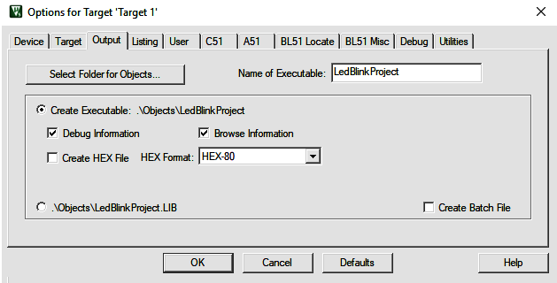
Press F7 or click on the Build button to start compiling the code. If there is no error, you can move on to the next step. You can either generate a HEX file to infuse into the desired hardware, or you can use the simulation technique to see whether the program is giving the desired output. In order to generate a HEX file, right-click on the Target1 node and select Options for Target 'Target 1'. We will get a dialog box showing different options. Click on the Output tab, and check the Create HEX File box (refer to the following screenshot). Additionally, click on the Device tab to confirm that the device selected is AT89C51. Then, click on the OK button:
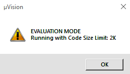
Keil's built-in Debug option can be used for code simulation. To do this, click on Debug | Start/Stop Debug Session; alternatively, you can press Ctrl + F5 as the shortcut key, or click on the Start/Stop Debug Session icon (it appears in the form of d) in the toolbar. The free version of the Keil tool has a condition that the running code size should not be more than 2 KB. You will get the following dialog box indicating that the running code has an upper limit of 2 KB:
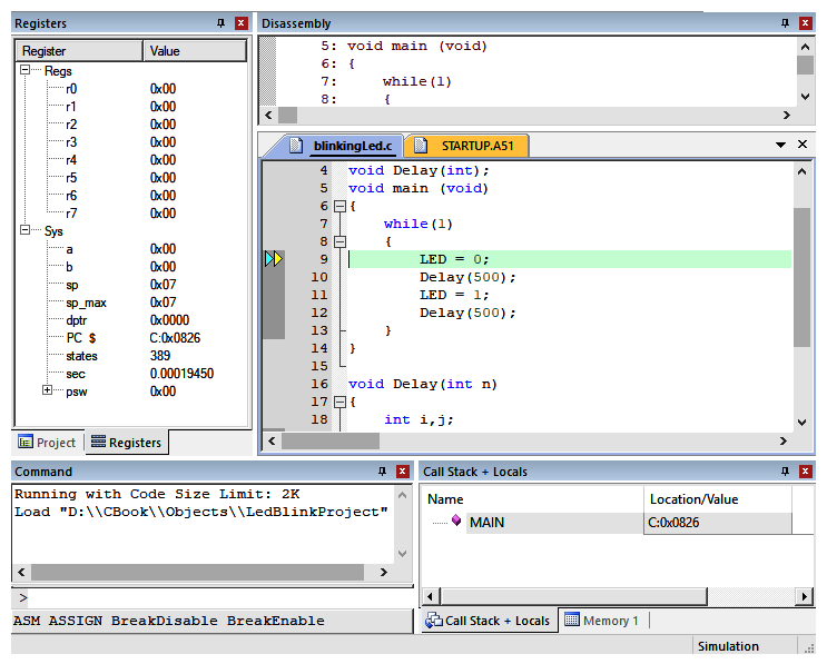
Click on the OK button to move further. Now the Project workspace window shows most of the SFRs as well as the GPRs, r0 to r7, as follows:
Click on the Run icon from the toolbar or press F5. To see the output on ports go to Peripherals | Select I/O ports | Port 1. You will get the blinking LED on Port1, as shown in the following screenshot. You can see that there is a LOW signal in bit0 of the Port1 and a HIGH signal on the same bit:

Voilà! We've successfully created a blinking LED using a microcontroller port. Now, let's move on to the next recipe!