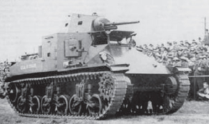
The US Army did not possess a medium tank in the 1930s, although several developmental designs existed on paper, and in some cases, prototypes were built through the 1920s. These exhibited British influence and bore small-caliber, low-velocity guns. In May 1936 the Army’s Ordnance Committee directed the development of a new tank based on Infantry Board requirements.2 Designated the T5, the projected medium tank was an enlarged M2 light tank, the predecessor of the M3 and M5 Stuarts. Some M2 components were used in the T5, but the new tank was to have heavier armor and armament. The T5’s armament was little different from that on its light counterpart. It was envisioned as an infantry support tank and not for tank-to-tank combat.

The M2 medium tank of 1940 provided the basic design for the future M3 medium tank. Note the similar dual bogie wheels, steep glacis, centered driver’s compartment, although it provided multiple large vision ports, and side escape hatches. The corner machine gun sponsons can be seen.
The T5’s chassis was not unlike the future M3’s. The front glacis was well sloped, but the superstructure’s sides and rear were vertical and further made vulnerable by numerous vision/pistol ports. The centerline driver’s position had large shuttered ports to the front and sides. The high, boxy superstructure mounted a cramped centerline turret with the new 37mm M3 high-velocity gun. A .30cal machine gun in each of the four corner sponsons provided 360-degree defense. On either side of the turret and between the sponsons were manholes mounting a .30cal for antiaircraft, which had to be dismounted to allow the turret to traverse. Two fixed forward-firing machine guns were fitted in the glacis near the track guard fenders. It lacked a coaxial machine gun, but bristling with eight, that was not a real deficiency. The five-man crewed tank had a high profile, a characteristic that would plague US tanks for years. Its armor was comparatively heavy for the era, the lower front being 1.125in. and the vertical sides 1.25in.
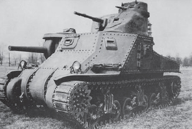
Left front view of the M3 tank displaying its full armament. An M2 machine gun tripod is stowed aft of the headlight. This tank mounts the 75mm M5 short gun, which has not been fitted with a muzzle counterweight.
The 1937 T5 Phase 1 prototype was fitted with a wooden mock-up superstructure, and various armament arrangements were tested. The Phase 2 was a never-built concept study. The Phase 3, after trying out further armament arrangements, was standardized as the M2 medium tank in summer 1938. The T4E2 had only a machine gun turret and a much-modified glacis, with the driver’s station moved to the left and a 75mm M1A1 pack howitzer mounted in the right front. This concept would be used in the M3.
With a major war in Europe, the first of 18 M2 medium tanks rolled out of the Rock Island Arsenal in Illinois in early 1940. The M2A1 was soon approved, featuring a redesigned turret, a more powerful engine, and other improvements. The first six already obsolete M2A1s were delivered in December 1940 and 88 more were delivered in 1941. Rock Island was incapable of producing sufficient numbers, and in August 1940, the Chrysler Motors Corporation was contracted for 1,000 M2A1s to be delivered by August 1942. The massive Detroit Tank Arsenal first had to be built by the US Army at Warren, Michigan, and would be operated by Chrysler.
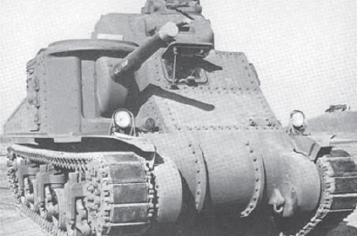
The right front of an M3 tank. This one still has the two .30cal machine guns in the left glacis seen beside the headlight. Beside the right headlight can be seen the siren, meant to be a psychological weapon.
Battle reports from Poland told of the German PzKpfw IV with a short 75mm gun employed for infantry support and the PzKpfw III with a high-velocity 37mm. Both tanks had low profiles. In a rush to field something comparable, work began in the United States on what was hoped to be a formidable tank, the M3 medium. The German offensive into the Low Countries and France, coupled with the expanded use of the PzKpfw IV, reinforced the need for a heavily armed US medium tank. Additionally, in late 1940, PzKpfw IIIs began mounting a short 5cm gun. The Chrysler M2A1 contract was canceled the same month it was let, and a new contract was granted for 1,000 M3s. The existing M2A1s were used as training tanks.
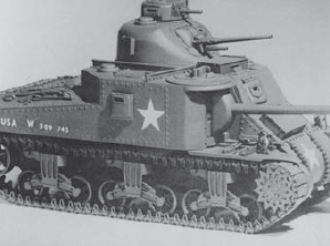
This later M3A5 has the side escape hatches eliminated. Note the ventilator added behind the escape hatch aft of the main gun and the equipment stowage boxes on the glacis and over the driver’s compartment. These were usually removed in combat. Note the return rollers are fitted to rearward extensions at the top of the bogie wheel suspension.
In June 1940 the M3 tank design was outlined and later standardized on July 11 without a completed design, much less a prototype. In the rush to produce it, the tank was never assigned a developmental “T” designation. European battlefield reports led to the sponson-mounted 75mm being added during its design. Its traverse limitations were understood, but no conventional turret capable of housing it was available.
The Ordnance Department had promised M3 plans to Chrysler by November 1940, but they did not arrive until February 1941. The first hand-built pilot model was run out on April 12 and shipped to Aberdeen Proving Grounds in Maryland on May 3. The tank arsenal commenced production in July 1941 with the first production model completed on July 8. An additional order for 1,200 M3s was placed that month.
In the same month that the M3 contract was let, the design of the T6 (M4) Sherman medium tank was submitted. An M4 prototype was delayed until the M3 entered production. The M4’s design was approved in April 1941 with the goal of rapidly mass-producing a fast, reliable tank. The design borrowed heavily from the M3 and incorporated improvements learned from British experience in Africa. Borrowing from the M3’s design helped speed up development and made it easier to convert production lines. The first pilot M4 was turned out in September, standardized in October, and full production began in February 1942. It would replace the M3 by August 1943.
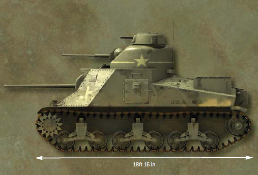
Most medium tanks of the era, including the PzKpfw III, were laid out similarly. The 360-degree revolving turret was situated just forward of center. It mounted the tank’s main gun plus a coaxial machine gun. The turret was manned by the tank commander, gunner, and loader. The driver and radio operator were in the forward portion of the hull; the latter was also the bow machine gunner. The engine was in the rear, protected by a heavy, ventilating louvered cover. The fuel tanks were usually on either side of the engine. Most tank designers strove to maintain a low profile and to incorporate as much sloped armor as possible to improve the armor’s ballistic efficiency.
The M3 deviated significantly from the typical tank layout. The most noticeable feature of the 31-ton M3 was its inordinately high profile, due to its secondary gun turret and commander’s cupola. The mounting of the main gun in a right front sponson and the secondary gun mounted on a small turret also deviated much from conventional tank design. While the glacis was well sloped, much of the superstructure was only slightly angled or vertical, especially the sides and rear of the superstructure and hull.
The driver sat on the centerline, rather higher than most drivers. This gave him a better field of observation but with greater exposure. To his left were two fixed bow machine guns. After June 1942 the leftmost gun was deleted as being redundant. One or two M2 tripods were provided for dismounted use. A large driver’s hatch with an indirect vision device was set at head level. Early M3s had only a vision slit that could be used as an awkward exit hatch. Beside the driver’s left shoulder was an observation/pistol port. In the right front portion of the hull was the main gun, either an M2 or M3 75mm gun on an M1 mount. This was a large, horizontally rotating curved shield for traversing, and set in it was the smaller, elevating gun shield. The gunner sat to the gun’s left and the assistant gunner behind him. The gunner aimed using an M1 periscope with an integral M21 telescope situated in the top of the hull, but an M15 optical sight was later mounted beside the gun. A hatch was positioned over the assistant gunner’s seat. The radio operator sat behind the driver, just forward of the turret. This became the assistant gunner’s seat after the radio operator was deleted, at which time the driver took over as radio operator. This conserved manpower, but increased the driver’s workload. On both sides of the superstructure were escape hatches with inset observation/pistol ports. These ports were fitted with bulletproof glass vision blocks called “protectoscopes.” An observation/pistol port was set in the right rear of the superstructure over the engine compartment. M3A3s and later models had the side escape hatches welded shut, and an escape hatch was provided in the belly, but this made it more vulnerable to mines. These side hatches allowed spalling – bullet and shell fragments – to enter through seams. The secondary gun turret was on a 54.5in.-diameter ring with a well-sloped front and offset to the left rear of the superstructure. The 37mm M5 or M6 gun on an M24 combination mount had a machine gun fitted to the right and the sight to the left. The commander was to the left of the 37mm and had a cupola atop the turret, mounting a machine gun in the right side and a vision port in the left. The cupola could be rotated independently of the turret. Being manual it was too slow to effectively track aircraft, its intended purpose. The commander’s seat was fitted inside the turret, but the 37mm gunner’s seat was on the turret floor to the gun’s left and the assistant gunner’s to the right of the gun on the turret shield. An observation/pistol port was set in the turret’s right rear quadrant. The turret crew was separated from the fighting compartment by a circular shield extending down into the superstructure. There were ventilators aft of the assistant gunner’s hatch atop the superstructure, to the left of the driver on the roof, and on the right top of the turret. Flat equipment boxes were fitted to the glacis below the driver’s port and over his roof and two large boxes on the sides of the engine deck. There were often removed.
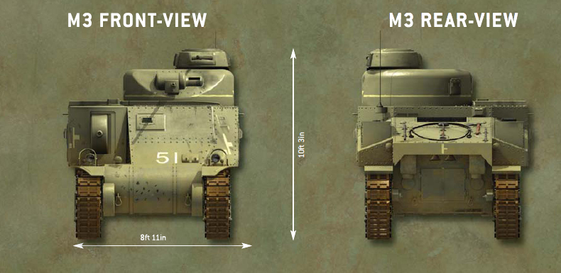
The 2d Battalion, 13th Armored Regiment was the only US unit in the Kasserine Pass battles equipped with M3 mediums bearing lusterless olive drab paint (OD No. 9: 33070), often partly camouflaged by hand-smeared mud. The unit still used the January 1942 Armored Force specified identification of yellow stars and a band on the turret as less conspicuous markings; most units had reverted to white. The vertical bar identified the battalion with a short horizontal bar on the right: top Co D, middle Co E, and lower Co F. The detached bar to the left identified the platoon, 3d Platoon if at the bottom. The white tank number is painted on the glacis.
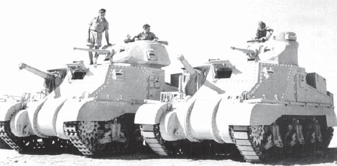
This photograph clearly illustrates the M3 Grant tank on the left with the larger British-designed turret, and the M3 Lee on the right with the American-designed turret. (Patton Museum)
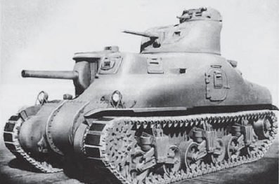
Only 300 of the cast hull M3A1 were built. Later variants of M4 Sherman tanks would use the cast hull.
The five-speed transmission was in the forward portion of the hull, with the propeller shaft running beneath the floor back to the engine. The auxiliary power generator, providing electrical power to operate the turret, radio, and lights when the engine was shut down, was in the back of the fighting compartment. The engine was in the rear hull with the air-cooled radiator aft and fuel tanks containing 175gal on either side. The engine was accessed through rear twin doors on most models.
A substantial amount of ammunition was carried in the M3: 46 rounds of 75mm, 178 rounds of 37mm, 9,200 rounds of .30cal for the three or four machine guns, 1,200 rounds of .45cal for the two Thompson submachine guns and six pistols, and 12 hand grenades (4xMk II fragmentation, 4xMk III offensive, 2xAN/M8 white smoke for screening, and 2xM14 thermite for destroying the guns if abandoned).
M3 production began in August 1941, and there were six US variants of the M3 tank. Five companies produced the variants, which were mostly of riveted construction. The bow was cast in three sections and riveted together, common to all variants. The 37mm turret and cupola were cast on all models. The M3 was powered by a Continental R-975-EC2 or EC1 radial aircraft engine. This was a nine-cylinder engine, burning 92-octane gasoline. The same engine powered the M3A1 and M3A2 variants. The M3 saw the largest production run and was the only one to see combat in US hands in Africa. It could be fitted with either 75mm M2 or M3 guns and 37mm M5 or M6 guns. M3 production ceased in August 1942.
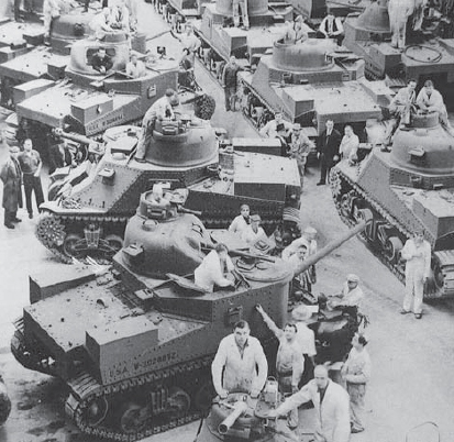
The Chrysler production line at the Detroit Tank Arsenal. Here the final M3A5s are being completed and M4 Sherman production would soon begin.
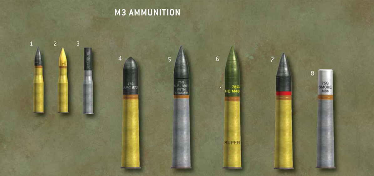
1. 37mm M52 APC
2. 37mm M63 HE
3. 37mm M2 canister
4. 75mm M72 AP-T
5. 75mm M61 APC-T
6. 75mm M48 HE
7. 75mm AP composite
8. 75mm M83 smoke

The Americans used this Browning .30cal machine gun on the M3 which was basically the same version as used by the infantry. However, the tank version was designated “fixed,” fitted as a coaxial gun or inside the commander’s cupola. Ammunition was issued in cans containing 250 rounds in web belts with one trace (red tip) per four ball or AP (black tip) rounds.
The M3A1 was the only model with an entirely cast hull and was otherwise identical to the M3. Only a comparatively small number were produced between February and August 1942. While most had the same engine as the M3, 28 had Guiberson T-1400-2 diesel engines and were designated the M3A1 (Diesel). Only 12 M3A2s were built between January and March 1942, all with welded hulls and otherwise identical to the M3A1. The M3A2 was essentially a prototype for the M3A3.
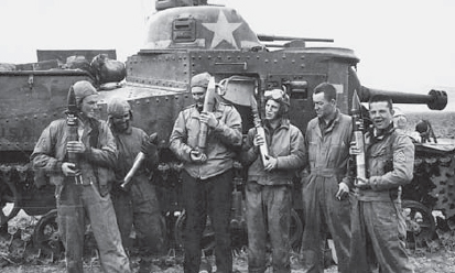
This crew seems to be making jest of the older and smaller 75mm M72 AP-T round held by the second man from the left. Most hold the new M61 APC-T rounds while the middle man holds an M48 HE round. Note the muzzle counterweight on the M5 gun.
Only just over 900 M3A3s and M3A5s were produced between January and December 1942, differing only in the M3A3 having a welded hull and the M3A5 a riveted one. Both had General Motors 6046 diesel engines in order to free up aircraft engines. The GM 6046 comprised two GM 6-71 truck engines linked together. Another difference from the diesel-engined models was that engine access was via a lower plate and a pair of louvered top deck doors. The variant that deviated the most was the riveted-hull M3A4, with just over one hundred built between June and August 1942. In another effort to eliminate the need for aircraft engines, it was provided with a Chrysler A-57 gasoline engine. This was actually five automobile engines mounted in a star pattern and meshed together, totaling 30 cylinders. This required the rear hull to be extended 14in. resulting in 6in. wider gaps between the suspension bogies.
When the British began purchasing American-made tanks in 1940, they bestowed upon them nicknames based on the names of American Civil War generals as an easy means of identification. While designated, for example, General Grant, they were commonly called the “Grant.” These names were adopted informally by the Americans but never officially. Tankers simply called them “M3” or “M4.” The terms “Lee” and “Sherman” were seldom used by American tankers. US tanks commonly used by the Commonwealth in North Africa included:
M3-series Stuart light tanks
M3-series Lee medium tanks
M3-series Grant medium tanks (Lee with UK-modified turret)
M4-series Sherman medium tanks
M5-series Stuart light tanks (aka “Honey”)
American numeric model designations can be confusing. Since the 1930s the United States designated light and medium tank series beginning with M1. This resulted in both light and medium tanks being used in North Africa that were designated the M3 (another reason the British bestowed nicknames). To break the chain of confusion, M4 was skipped for the next light tank, resulting in the M5, to prevent confusion with the M4 medium tank. (There is no hyphen in US weapon/equipment designations.)
| M3 medium tank production, August 1941–December 1942 | ||||||
| Company | M3 | M3A1 | M3A2 | M3A3 | M3A4 | M3A5 |
| American Locomotive Co. | 385 | 300 | - | - | - | - |
| Baldwin Locomotive Works | 295 | - | 12 | 322 | - | 591 |
| Chrysler Detroit Tank Arsenal | 3,243 | - | - | - | 109 | - |
| Pressed Steel Car Co. | 501 | - | - | - | - | - |
| Pullman Standard Manufacturing Co. | 500 | - | - | - | - | - |
| Total | 4,924 | 300 | 12 | 322 | 109 | 591 |
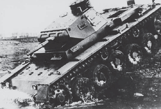
One of the 10 PzKpfw III Ausf A light tanks built for testing in May 1937. None of these saw combat service.
In 1935 the new German Panzer-Divisionen were being equipped with machine gun-armed PzKpfw I and II light tanks. Originally envisioned only as training tanks while more potent light and medium tanks were developed, they were, in fact, the most common tanks employed in Poland, the Low Countries, and France, along with impounded Czechoslovak tanks. The Panzer I and II also saw use in Africa. In January 1934 the Heereswaffenamt (Army Weapons Office) held a conference attended by representatives of the Kraftfahrkamptruppen (Motorized Battle Troops) to determine the requirements for future light and infantry support (medium) Panzerkampfwagen (armor battle vehicles) – tanks. These new tanks had an upper weight limit of 24 metric tons (26.5 US tons) owing to European bridge limitations. Knowing enemy tank armor was certain to improve, German tankers desired a 5cm gun on the light tank. The Army Weapons Office and artillery wanted the 3.7cm gun for ammunition compatibility, the same as the new infantry antitank gun, and not have to allocate production lines to another weapon. To conserve resources this was agreed to, but the design had to incorporate a turret and a 150cm (59in.) turret ring capable of mounting a 5cm in the future. The medium tank would mount a short-barreled 7.5cm.
The development of the new tanks was done secretly to mask German rearmament. It would be conducted under cover designations as the leichttraktor and mittlerestraktor (light and medium tractors) with the project designation Vollkettenfraftfahrzeug (experimental tracked motorized vehicle) 2000. The tanks were also bestowed the cover designations of Zugführerwagen and Bataillonsführerwagen (platoon and battalion commander vehicles). These tanks would become the PzKpfw III light and IV medium, to be popularly known to the Allies as the Mk III and Mk IV tanks, designations given by the British. The German tanker simply called them the Panzer III and Panzer IV, or Panzer drei and Panzer vier.
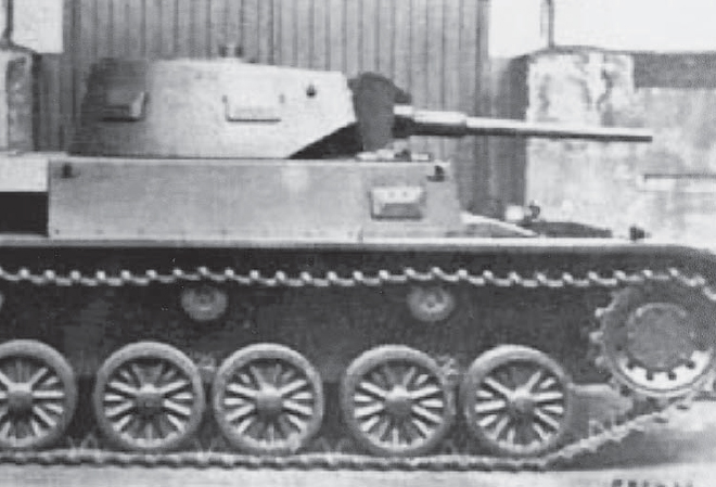
Another view of a PzKpfw III Ausf A. The six bogie wheels of later models were smaller than this prototype’s.
Daimler-Benz A.G., Henschel, Krupp, Maschinenfabrik Augsburg-Nürnburg (MAN), and Rheinmetall-Borsig were requested to submit proposals in 1935. The design submitted by Daimler-Benz at Berlin/Marienfelde was selected. Prototypes included the better aspects of the Henschel and MAN designs and were tested between 1936 and 1937 at the Ulm, Sennelager, Döllersheim, and Kummersdorf automotive proving grounds while gun testing took place at Meppen.
The PzKpfw III was of conventional design similar to the Krupp PzKpfw IV, which was actually fielded before the PzKpfw III. From a distance it was difficult to tell the two apart (PzKpfw III had six bogie wheels and the PzKpfw IV had eight). Efforts were also made to make some components interchangeable between the two. The PzKpfw III was assigned the Sonderkraftfahrzeug (special motorized vehicle) designation of SdKfz 141.3
The bow of the PzKpfw III was blunt and boxy with a vertically stepped front compartment. The driver was on the left and the radio operator on the right with a ball-mounted machine gun. On the forward horizontal deck over their knees were small break servicing hatches that could be used as escape hatches. The driver had a shuttered vision port with “armored” binoculars, and small vision/pistol ports were on both sides of the forward portion of the superstructure. A small escape hatch was set in the lower hull sides above the bogie wheels and between the first and second return rollers. These were deleted with the Ausf M.4 The three-man turret had a heavy gun mantlet mounting the main gun with two coaxial machine guns to the right in the Ausf A to C and the sight to the left. Later versions had one coaxial gun. The turret sides were gently sloped and the back slightly rounded. There were vent/pistol ports on the forward sides and split door escape hatches on both sides of the turret’s rear sides, each with a vision port. The vision ports/slits were protected by bulletproof glass blocks. In the rear center of the turret top was the raised commander’s “dustbin-type” cupola with a split hatch on top. Five vision slits provided 360-degree observation. The gunner sat to the gun’s left, and the loader, who also operated the coaxial machine gun by a foot-peddle trigger, sat to the right. The gunner manually rotated the turret, and the loader had an auxiliary traverse handle. The commander and gunner had seats mounted on the turret wall, but the loader did not. There was no turret floor, so the loader had to walk on the hull floor as the turret traversed.
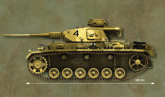
Panzer-Regiment 7 tanks were painted yellow-brown (RAL 8000), sometimes with the original dark gray (RAL 7027) showing through. Sometimes about 20 percent of the tank was splotched with gray-green (RAL 7008). Sometimes continental-painted tanks were merely coated with used oil and dusted with sand. The company number was painted in black on the turret side, Kompanie 4, with the tank number in smaller characters. The regimental insignia is seen on the equipment bin behind the turret. The Balkenkreuz (beamed cross) is on the hull and was often partly obscured by mud or lightly sprayed paint.
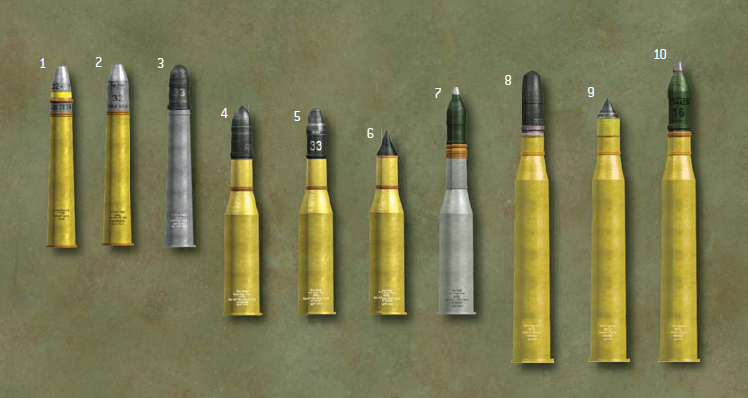
1. 3.7cm Sprgr 18
2. 3.7cm Sprgr 40
3. 3.7cm Pzgr
4. 5cm Pzgr (KwK 38)
5. 5cm Pzgr 39 (KwK 38)
6. 5cm Pzgr 40 (KwK 38)
7. 5cm Sprgr 38 (KwK 38)
8. 5cm Pzgr 39 (KwK 39)
9. 5cm Pzgr 40 (KwK 39)
10. 5cm Sprgr 38 (KwK 39) 7

The German 7.9mm MG.34 mounted in tanks was the same as the standard infantry machine gun. In February 1941 a tank version with a heavier barrel jacket lacking ventilator holes was authorized for installation in new production tanks. Standard combat ammunition was the “bullet with steel core” (black tip, red rimmed primer) as opposed to lead cores to achieve better penetration. The recoil-operated gun fired at 800–900 rpm.
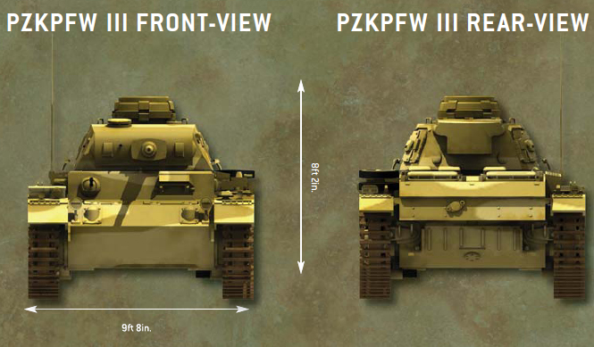
The engine was in the rear, accessible through upper deck hatches, along with changing arrangements of air ventilators. This engine was a Maybach HL108TR 12-cylinder, 300-horsepower gasoline. The transmission was ten-speed, although later a six-speed was introduced to ease the driver’s workload. The two fuel tanks were on either side of the engine in the Ausf A to C, carrying 125 liters (33gal), while later models had four tanks that held 320 liters (85gal). The air-cooled radiators, exhaust, and muffler systems were in the hull’s rear.
Numerous modifications were introduced during the PzKpfw III’s production including changes to the cupola, gun mantlet, hatches, vision/pistol ports, escape hatches, armor skirts, air intakes, engine covers and hatches, spaced armor arrangements, and headlights, among others. Changes were also made to the six bogie wheels, three return rollers, rear idle wheels, and front drive sprockets in efforts to correct roughriding suspension problems that effected gun accuracy. Track width was 36cm (14.1in.) with 99 links, later widened to 40cm (15.7in.) with the Ausf H.
| PzKpfw III light tank production, 1937–43 | ||
| Ausführung | Number | Years |
| A | 10 | 1937 |
| B | 15 | 1937 |
| C | 15 | 1937–38 |
| D | 30 | 1938 |
| E | 96 | 1938–39 |
| F | 435 | 1939–40 |
| G | 600 | 1940–41 |
| H | 308 | 1940–41 |
| J (5cm L/42) | 1,549 | 1941–42 |
| J (5cm L/60) | 1,067 | 194 2 |
| L | 653 | 194 2 |
| M | 250 | 1942–43 |
| N | 660 | 1942–43 |
| Total | 5,688 | |
Ten of the first model, the PzKpfw III Ausf A, were built from May 1937 followed by 15 each Bs and Cs and then 30 Ds, used for troop trials into 1938. From 1938 to 1939, 96 Ausf Es were built. Only 98 PzKpfw IIIs and just over twice that many PzKpfw IVs were available in September 1939. Large-scale production did not begin until 435 Ausf Fs were built from 1939 to 1940 and used in France. Frontal armor upgrades were implemented on the Ausf D and later models. Later versions were built in the hundreds until the introduction of the Ausf J in 1941 with over 2,600 built. The PzKpfw III and components were produced by Daimler-Benz A.G., Henschel und Sonn A.G., Altmaerkische Kettenwerk, GmbH, Waggonfabrik Wegmann A.G., Muehlenbau und Industrie A.G., Maschinenfabrik Augsburg Nuernburg A.G., and Maschinenfabrik Niedersachen Hannover GmbH.
The PzKpfw III Ausf A to E, and some Ausf Fs were armed with a 3.7cm Kwk 36 L/45 gun. As foreseen, a larger caliber weapon was needed, and so the short-barreled 5cm KwK 38 L/42 was used on the Ausf F to H from June 1940. The 3.7cm was found inadequate against heavily armored French tanks such as the Char B, leading to it being called the Türklopfer (doorknocker). Existing PzKpfw IIIs were to be upgraded by December, but this was not completed as there were still outstanding requests for upgrading in June 1941. From early 1942 later Ausf Js were armed with the long 5cm KwK 39 L/60 gun as were the Ausf L and M, after experiencing the Soviet T-34 in summer 1941. The Germans differentiated between the two 5cm gun models by calling them a PzKpfw III kurz (short) and lang (long). The Ausf N of July 1942, the last version, had the 7.5cm KwK 37 L/24 short gun as originally mounted on the PzKpfw IV. Its primary role was to protect Tiger tanks.
By 1942 the roles of the PzKpfw III and IV were reversed. The lighter PzKpfw III became the infantry support tank, and the PzKpfw IV Ausf H with a long high-velocity 7.5cm KwK 40 L/48 gun was the main medium tank intended to take on other tanks. The PzKpfw III was the second most produced German tank being surpassed by the PzKpfw IV.
The early models were armed with a 3.7cm gun and twin coaxial machine guns with 120 rounds of 3.7cm and 4,435 rounds of 7.9mm for the three machine guns. Those with one coaxial gun had 2,700 rounds, although the Ausf L and M carried 3,750 rounds. A quantity of 9mm ammunition was carried for the crew’s five pistols and one submachine gun as were hand grenades and 24 2.6cm flare pistol cartridges. The 5cm gun-armed tanks had 99 rounds (typical load was 58 HE, 36 AP, and 5 AP40 rounds) until the Ausf J with 84, and the Ausf L and M carried 92. The number of storage bins is misleading as to the number of rounds actually carried. A British examination of two abandoned PzKpfw IIIs in Tunisia revealed that besides the 99 bins, one had another 86 rounds stacked on the floor, and the other had 83 to total 185 and 182 rounds, respectively. One tank carried 98 AP and 80 HE while the other had 111 AP and 51 HE. A few from the bins had been fired and other loose rounds may have been before the tanks were captured. In comparison to Allied tanks which carried a high percentage of AP, the Germans carried a high percentage of HE to use against soft-skin vehicles, stone-constructed fighting positions (sangars), and personnel.
2 A machine gun-armed M1 medium tank was standardized in April 1939, which had been built in 1936 as the T4. The 18 in service were declared obsolete a year later.
3 The SdKfz category designation was assigned to most standard German military vehicles, 101–200 being assigned to full-tracked combat vehicles.
4 Ausf stands for Ausführung (version), a letter appended to the PzKpfw designation identifying a sub-variant.