Chapter 9
Basic Corridors
The corridor object is a three-dimensional model that combines the horizontal geometry of an alignment, the vertical geometry of a profile, and the cross-sectional geometry of an assembly.
Corridors range from extremely simple roads to complicated highways and interchanges, but they aren't limited to just road travel ways. Corridors can be used to model many linear designs. This chapter focuses on building several simple corridors that can be used to model and design roads, channels, and trenches.
In this chapter, you will learn to:
- Build a single baseline corridor from an alignment, profile, and assembly.
- Use targets to add lane widening.
- Create a corridor surface.
- Add an automatic boundary to a corridor surface.
Understanding Corridors
In its simplest form, a corridor combines an alignment, a profile, and an assembly (see Figure 9.1).
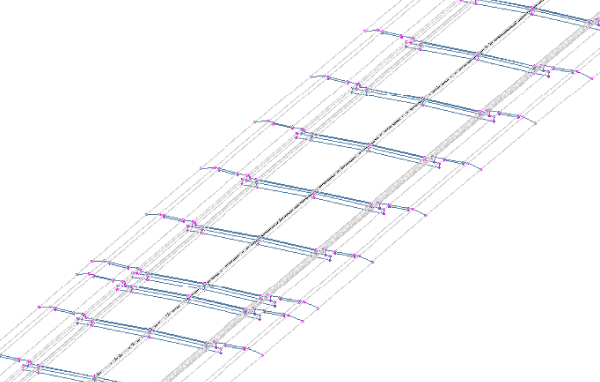
Figure 9.1 A corridor shown in 3D view
You can also build corridors with complex combinations of alignments, profiles, and assemblies to make complicated intersections, interchanges, or branching streams (see Figure 9.2).
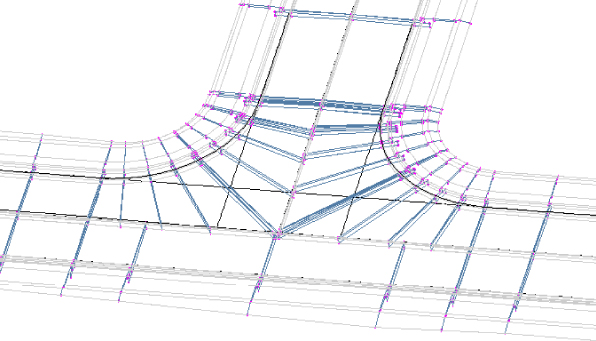
Figure 9.2 An intersection modeled with a corridor
The horizontal properties of the alignment, the vertical properties of the profile, and the cross-sectional properties of the assembly are merged to form a dynamic model that can be used to build surfaces, sample cross sections, generate quantities, and much more.
Most commonly, corridors are used to model roads, but they can also be adapted to model berms, streams (see Figure 9.3), trails, and even parking lots.
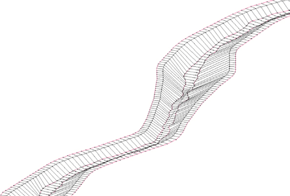
Figure 9.3 A stream modeled with a corridor
Recognizing Corridor Components

First, let's look at some important corridor components you will want to become familiar with before proceeding. Baseline, region, assembly, frequency, and target are all parts of a corridor that you will encounter even on your first design.
Baseline
The first component for any corridor is a baseline. The baseline is composed of two Autodesk® AutoCAD® Civil 3D® objects, an alignment providing the horizontal layout, and a profile providing the vertical layout. The baseline generates the backbone on which the assembly is placed. Corridors can contain more than one baseline. Therefore, a network of roads can be modeled using one corridor.
In most of the examples in this chapter, the baseline will correspond to the centerline alignment with a profile representing the elevation at the crown of a proposed road. However, this is not always the case, as we will explore in more depth in Chapter 10, “Advanced Corridors, Intersections, and Roundabouts.” As your designs become more detailed, you may have corridors with multiple baselines.
Region
When the geometry along a baseline changes enough to warrant a new assembly, a new region is needed. Regions specify the station range where a specific assembly is applied to the design. There may be many regions along a baseline to accommodate design geometry, but the regions may not overlap. Therefore, each region has a start station and an end station, with the end station of one region often matching the start station of the next region.
Assembly
Marker points, links, and shapes are coded into the subassemblies that the assembly contains, as you saw in Chapter 8, “Assemblies and Subassemblies.” Assemblies are the third Civil 3D object that is required to generate the corridor by providing cross-sectional information to be applied along some or all of the length of the baseline. Figure 9.4 shows a symmetric roadway assembly that consists of lanes, curbs, sidewalks, and daylight links.
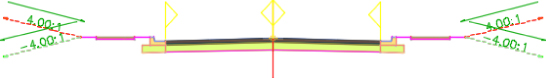
Figure 9.4 Typical roadway assembly
Frequency
Frequency refers to how often the assembly is applied to the corridor design. You can set the frequency for the corridor as a whole or for each region.
The frequency value will vary depending on the situation. The default frequencies of the stock Civil 3D templates are 25' in Imperial units and 20 m for metric units. But like many of the settings in Civil 3D, these defaults can be changed in your drawing or template settings by using the following simple steps:
- On the Settings tab of Toolspace, expand the Corridor &cmdarr; Commands branch.
- Right-click the Create Corridor command and choose Edit Command Settings to display the Edit Command Settings – Create Corridor dialog.
- Expand Assembly Insertion Defaults.
- Change Frequency Along Tangents, Frequency Along Curves, Frequency Along Spirals, Frequency Along Profile Curves, or any other of the multitude of default settings associated with creating a corridor.
A new feature in Civil 3D 2016 is an alternative to configuring frequency along curvatures. Instead of using a constant distance value for frequency, frequency can be triggered by the mid-ordinate distant value. This frequency setting can be applied to curves in the alignment or curves in offset targets (targets will be discussed in the next section), resulting in more frequent insertions of assemblies along smaller curves and less frequent insertions of assemblies along larger curves. This produces a more precise and accurate 3D model without a lot of manual overrides on the region level.
In addition to the frequencies based on the alignment or profile entity, Civil 3D can place frequency lines at special stations such as horizontal geometry stations, superelevation critical stations, profile geometry stations, profile high/low stations, and offset target geometry stations. You can also manually create additional frequency stations for things such as driveways or culvert crossings.
Target
As you learned in Chapter 8, three types of targets can be configured in a corridor: a target surface, a target elevation, and a target offset. Targets can be used in lieu of additional assemblies to change corridor geometric characteristics such as cross slope (elevation targets) and lane width (offset target). Surface targets can be used in daylighting or roadway rehabilitation scenarios. Some targets are optional, whereas others are required. For a detailed explanation on targeting for each stock assembly, refer to the help files.
Corridor Feature Lines
When a corridor is created, corridor feature lines are generated. These feature lines can represent back of curb, top of curb, flow lines, edges of pavement, crowns, and any other breakline that would be produced based on your proposed typical roadway section. Corridor feature lines are drawn along the corridor, connecting marker points of identical codes in between assembly frequencies, as shown in Figure 9.5. This takes traditional roadway design to another level: A collection of cross sections occurring at specified frequencies becomes a dynamic three-dimensional object model.
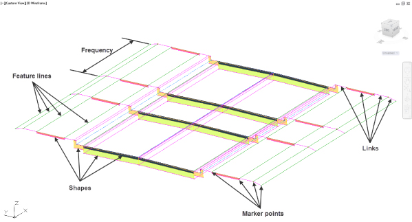
Figure 9.5 The anatomy of a corridor
Later in this chapter, you will take a closer look at corridor feature lines.
This exercise gives you hands-on experience in building a corridor model from an alignment, a profile, and an assembly:
- Open the
0901_RoadCorridor.dwgfile or0901_RoadCorridor_METRIC.dwgfile. You can download these files fromwww.sybex.com/go/masteringcivil3d2016. Note that the drawing has several alignments, profile views containing the existing and design profiles for each, an assembly, and an existing ground surface. - From the Home tab
 Create Design panel, choose Corridor to display the Create Corridor dialog.
 - In the Name text box, name the corridor North River Crossing.
Keep the default values for Corridor Style and Corridor Layer.
- Set Alignment to ROAD C and set Profile to FG-ROAD C (take extra care not to select EG-ROAD C by mistake).
Notice that you can use the small green selection button to select the object on the screen instead of using the drop-down list if you prefer.
- Verify that Assembly is set to Urban 14' Single-Lane (or Urban 4.5m Single-Lane for metric users).
- Verify that Target Surface is set to Existing Surface.
- Verify that the Set Baseline And Region Parameters check box is selected.
The Create Corridor dialog should now look similar to Figure 9.6.
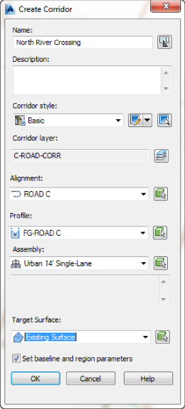
Figure 9.6 The Create Corridor dialog
- Click OK to accept the settings and to display the Baseline And Region Parameters dialog, as shown in Figure 9.7.
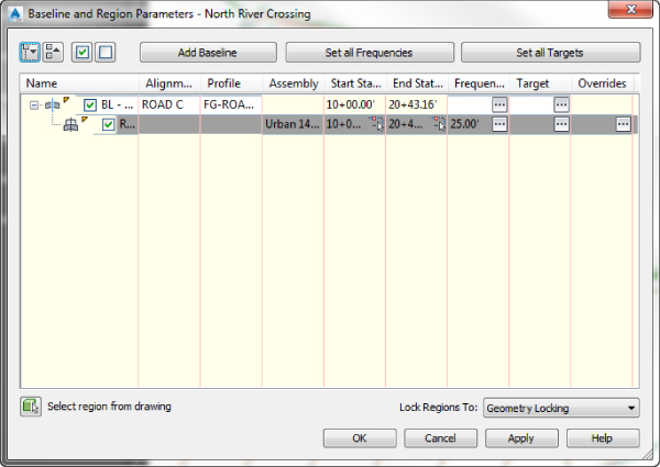
Figure 9.7 The Baseline And Region Parameters dialog
Notice that there is currently one baseline containing one region. The Start Station and End Station values of the region match those of the baseline.
Most of the other settings have already been set from the information you provided in the Create Corridor dialog, but let's take a few minutes to look at some of the settings in the Baseline And Region Parameters dialog.
- Click the ellipsis button in the Frequency column in the first row associated with the baseline (BL) to display the Frequency To Apply Assemblies dialog.
By clicking the ellipsis in the first row that is associated with the baseline, you will be setting the frequency for all of the regions within that baseline. In this instance you have only one region, but setting them all at once is a good habit to get into when applicable. You could also click the Set All Frequencies button, which would set the frequency for all the baselines and all the baseline regions.
- Examine the settings in the Frequency To Apply Assemblies dialog, as shown in Figure 9.8.
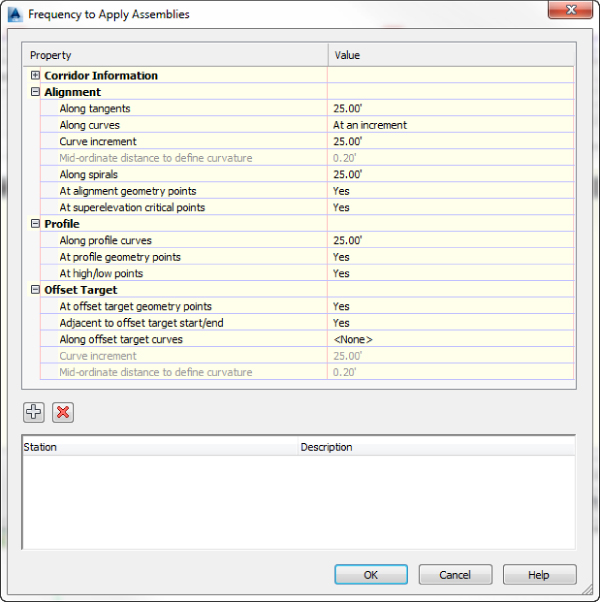
Figure 9.8 The Frequency To Apply Assemblies dialog
You can vary the default frequency distance for the portions of the region along tangents, curves, spirals, and profile curves. You can also base frequency along alignment and offset curves by curvature (mid-ordinate distance) instead of by increment. In addition, you can add frequency lines at various geometry points. At the bottom of the dialog you can add a user-defined station.
- Click OK to accept the settings in the Frequency To Apply Assemblies dialog.
- Click the ellipsis button in the Targets column in the baseline row to display the Target Mapping dialog.
The ellipsis buttons in this column behave the same way as the ellipsis buttons in the Frequency column. Notice that there is also a Set All Targets button, which can be used to set the targets for all of the baselines and all of the baseline regions.
- Examine the settings in the Target Mapping dialog, as shown in Figure 9.9.
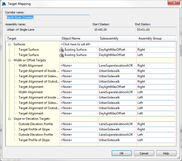
Figure 9.9 The Target Mapping dialog
The information in this dialog will vary depending on the subassemblies assigned to the assembly used for this corridor baseline but will always be broken into three categories: Surfaces, Width Or Offset Targets, and Slope Or Elevation Targets. Notice that because you selected Existing Surface as the target surface when creating the corridor, Existing Surface is already set as the target surface for the left and right subassemblies targeting a surface.
- Click OK to accept the settings in the Target Mapping dialog.
- Click OK to accept the settings in the Baseline And Region Parameters dialog.
If at any point you want to return to the information shown in this dialog, you can do so on the Parameters tab of the Corridor Properties dialog, which you will look at a little later in this chapter.
You will see a dialog warning you that the corridor definition has been modified and giving you two options: Rebuild The Corridor or Mark The Corridor As Out-Of-Date. Select the Rebuild The Corridor option.
If you click the check box at the bottom of this warning dialog that says “Always perform my current choice,” you will not see this warning dialog again.
You will receive an error message in Panorama, as shown in Figure 9.10, that reads “Intersection with target could not be computed,” “Intersection Point doesn't exist,” or something similar. You will rectify this issue in the following steps.
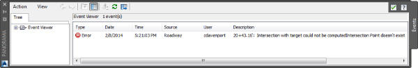
Figure 9.10 Corridor error in Panorama
If Panorama did not automatically display, from the Home tab
Palettes expanded panel, choose Event Viewer.
- Dismiss Panorama.
Your corridor should look similar to Figure 9.11.
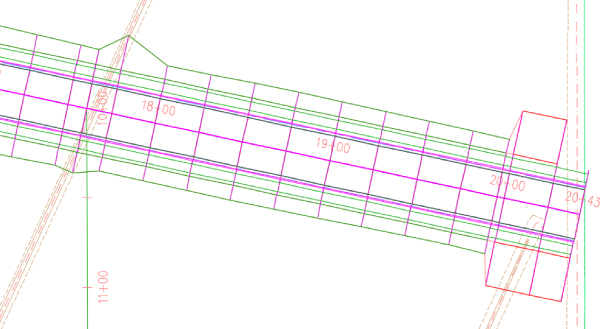
Figure 9.11 A portion of the nearly completed corridor
Now, let's try to figure out why those messages appeared in Panorama. In plan view, at the last station on the east end of the alignment, notice that on the left side some of the feature lines are not connecting (shown in Figure 9.11). Daylighting could not occur at the final station because the alignment is extending outside the outer edge of the surface. Furthermore, a look at the corridor in the Object Viewer shows a “waterfall” (see Figure 9.12).
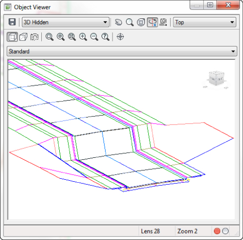
Figure 9.12 A “waterfall” at the end of the alignment viewed in the Object Viewer
The fact that the alignment is extending outside the outer edge of the surface isn't the only cause of the error in Panorama. If you take a look at the profile view for ROAD C, the FG-ROAD C profile does not extend to the end of the alignment, which explains the waterfall. A waterfall occurs when the profile used in the corridor is not providing elevation data along a station range of the alignment. Therefore, the corridor dives down to elevation zero in that station range. In this case, you need to shorten the corridor so that it builds along the station range matching FG-ROAD C.
- Select the corridor to activate the Corridor contextual tab.
- From the Corridor contextual tab Modify Corridor panel, choose the Corridor Properties icon to display the Corridor Properties dialog.

- In the Corridor Properties dialog, switch to the Parameters tab.
Notice in Figure 9.13 that the end station for the region is 20+43.16' (or 0+622.76m for metric users), which is based on the full length of the alignment. However, the design profile ends at 19+95' (or 0+608m for metric users). Even though there is no elevation assigned at 20+43.16' (or 0+622.76m for metric users), the corridor assumes an elevation of zero at this station, which creates this waterfall effect. To fix this, you need to tell the corridor to end the region at the final station of the design profile.
Note that even though the display value shows only two (or three) decimal places, the corridor examines up to eight decimal places of precision, which means that the value being displayed as the final station of the design profile may be a rounded-up value. If this is the case, this too will create a waterfall effect.
- Click into the End Station field for the region and enter 1995 (or 608 for metric users).
Entering the value with station notation (the plus sign) is not needed.
Notice that you could alternatively click the station picker button in this cell to select the station on the plan.
- Click OK to accept the settings in the Corridor Properties dialog.
- If you didn't click the check box at the last warning dialog, you will receive the same warning again. If so, select the Rebuild The Corridor option to allow the corridor to rebuild.
No new errors will appear in Panorama.
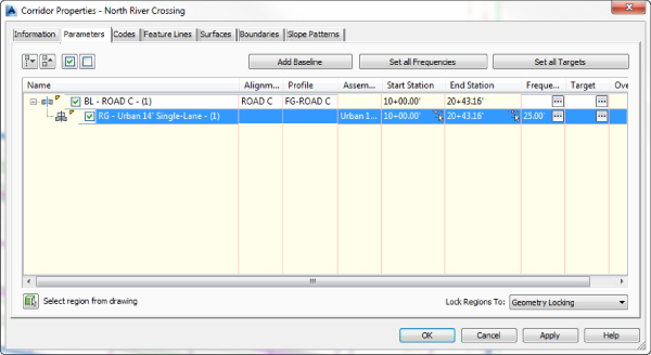
Figure 9.13 Corridor Properties dialog, Parameters tab
A quick look in the Object Viewer should reveal that the waterfall is gone. When this exercise is complete, you can close the drawing. A finished copy of this drawing is available from the book's website with the filename 0901_RoadCorridor_FINISHED.dwg or 0901_RoadCorridor_METRIC_FINISHED.dwg.
Rebuilding Your Corridor
A corridor is a dynamic model—which means that if you modify any of the objects used to create the corridor, the corridor must be rebuilt to reflect those changes. For example, if you make a change to the design profile, you must rebuild the corridor to bring it up to date. The same principle applies to changes to alignments, assemblies, target surfaces, and any other corridor building blocks or parameters.
You can access the Rebuild command by right-clicking the corridor name in Prospector, as shown in Figure 9.14.
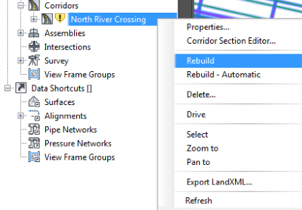
Figure 9.14 In Prospector, expand the Corridors branch and right-click the corridor name to rebuild it.
You can also rebuild the corridor or rebuild all corridors by selecting the corridor object and choosing Rebuild Corridor or Rebuild All Corridors from the Corridor contextual tab ![]() Modify Corridor panel, as shown in Figure 9.15.
Modify Corridor panel, as shown in Figure 9.15.
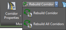
Figure 9.15 Rebuilding the corridor from the Corridor contextual tab
Tweaking Corridors
Your corridor may not be perfect on your first iteration of the design. Become comfortable getting into and working with the Parameters tab of the Corridor Properties dialog. You will spend the majority of your time modifying your corridor on this tab.
Whether you are building your first corridor or your five hundredth, odds are good that you will run into one of the following common issues:
- Problem The waterfall effect—your corridor seems to fall off a cliff, meaning the beginning or ending station of your corridor drops down to elevation zero.
- Typical Cause The range of your corridor is longer than the design profile.
- Fix This is exactly what you ran into in the first exercise. The corridor takes the initial station range from your alignment. However, sometimes you don't tie into existing ground at the exact alignment start and end stations, so you need to adjust the corridor stations accordingly.
If you need to check the exact start and end stations of the design profile, the best place to do so is the Profile Data tab in the Profile Properties dialog (as shown in Figure 9.16). Edit your corridor region to begin and end at the design profile station.
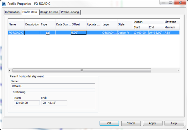
Figure 9.16 Check your Profile Properties dialog to verify the station range of the design profile.
Alternatively, you can use the station picker button to select the first and last corridor region stations by snapping to the first and last frequency lines that correspond to your profile geometry.
- Problem Your corridor seems to take longer to build and has irregular frequency stations. Also, your daylighting may not extend out to where you expect it (see Figure 9.17).
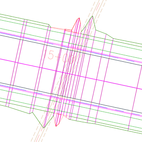
Figure 9.17 An example of unexpected corridor frequency
- Typical Cause You accidentally chose the existing profile instead of the design profile for your baseline profile. Most corridors are set up to place a frequency line at every vertical geometry point, and a profile, such as the existing profile, has many more vertical geometry points than a layout profile (in this case, the design profile). These additional points on the existing profile are the cause of the unexpected frequency lines.
- Fix Always use care to choose the correct profile. Either physically select the profile onscreen or make sure your naming conventions clearly define your finished grade as finished grade. If your corridor is already built, select the corridor, right-click, and choose Corridor Properties, as shown in Figure 9.18. On the Parameters tab of the Corridor Properties dialog, change the profile from the existing profile to the design profile.
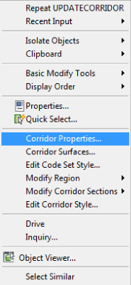
Figure 9.18 The context menu available on the Corridor object
Adding a surface target throws another variable into the mix. Here is a list of some of the most typical problems new users face and how to solve them:
- Problem Your corridor doesn't show daylighting even though you have a daylight subassembly on your assembly. You may also get an error message in Event Viewer, as shown in Figure 9.19.
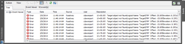
Figure 9.19 Error messages associated with missing areas of daylighting
- Typical Cause You forgot to set the surface target when you created your corridor.
- Fix Select the corridor, right-click, and choose Corridor Properties. On the Parameters tab of the Corridor Properties dialog, click the Set All Targets button. The Target Mapping dialog opens, and its first category is Surfaces. Click the <Click Here To Set All> text in the Object Name column field to display the Pick A Surface dialog. In this dialog, you can choose a surface for the daylight subassembly to target.
- Problem Your corridor seems to be missing areas of daylighting. You may also get an error message in Event Viewer, as shown in Figure 9.20.
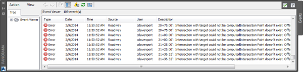
Figure 9.20 Error messages associated with missing areas of daylighting
- Typical Cause The Daylight link cannot find the target surface within the parameters you've set in the subassembly properties. This could also mean that the target surface doesn't fully extend the full length of your corridor or your target surface is too narrow at certain locations.
- Fix Add more data to your target surface. The daylighting subassemblies in your corridor need a surface to tie into at the slope, grade, or distance specified in subassembly properties.
You can also revisit your daylight subassembly settings to give the program a narrower offset or steeper slope or grade. Alternatively, you can adjust your alignment and/or profile to require less cut or fill, which would cause daylighting to occur over a shorter distance. Lastly, you can adjust your station range on the Parameters tab in Corridor Properties, as you did in the previous exercise.
If this is not possible, omit daylighting through those specific stations, and once your corridor is built, do hand-grading using feature lines or grading objects. You can also investigate other subassemblies such as LinkOffsetAndElevation that will meet your design intention without requiring a surface target.
Working with Corridor Feature Lines
Corridor feature lines are first drawn connecting marker points of the same code in between assembly frequencies. For example, a feature line will work its way down the corridor and connect all the Daylight points occurring from assembly to assembly. If there are Daylight points on the entire length of your corridor, then the feature line is drawn for the entire length of your corridor. If a region is defined along that same corridor without Daylight points, then the daylight feature line will end at that region.
The Feature Lines tab of the Corridor Properties dialog has a drop-down menu called Branching (see Figure 9.21) with two options: Inward and Outward.
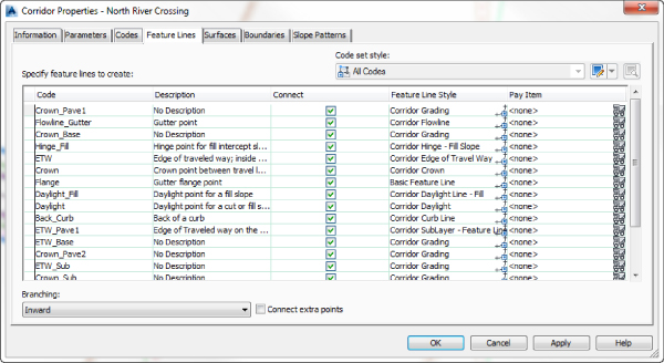
Figure 9.21 The Feature Lines tab of the Corridor Properties dialog
In the case of a two-lane road transitioning to a four-lane road, you would have two lane edges transitioning to four lane edges in the corridor. When branching inward, the feature lines representing those two lane edges will be drawn to the innermost lane edges of the four-lane road on their respective sides. When branching outward, the feature lines representing the two lane edges will be drawn to the outermost lane edges on their respective sides. This setting is particularly important for surface building purposes. Also on this tab is a check box labeled Connect Extra Points. If checked, this will cause the feature lines representing those two lane edges to branch out and connect to both the inner and outer lane edges on their respective sides (see Figure 9.22).
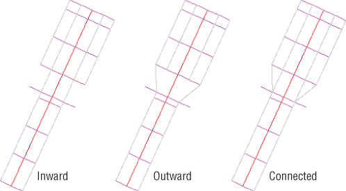
Figure 9.22 Feature line branching and connectivity options
As mentioned earlier, a feature line will connect the same point codes in between assembly frequencies by default. However, the Feature Lines tab of the Corridor Properties dialog allows you to eliminate certain feature lines on the basis of the point code. For example, if for some reason you did not want your Daylight points connected with a feature line, you could toggle that feature line off using the check box in the Connect column.
Corridor feature lines represent the linear features of your corridor like crown, pavement edge, flow line, back and top of curb, and sidewalk edges. Feature lines can also be generated for the edges of all pavement layers, base layers, and sub-base layers. You will be using feature lines in Chapter 14, “Grading,” for grading purposes. The difference between the two types of feature line is that corridor feature lines live in the Corridor object.
There are several types of objects you can extract from the Corridor object. If you select the corridor to activate the Corridor contextual tab, you will notice that the Launch Pad panel, shown in Figure 9.23, offers tools for extracting points, alignments, profiles, polylines, and feature lines. The latter four objects are created from the corridor feature lines.
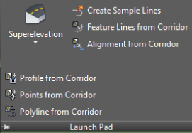
Figure 9.23 Launch Pad panel of the Corridor contextual tab
A step-by-step explanation of how to extract a corridor feature line is given in the next exercise.
In the case of extracting a feature line, you have the choice of keeping the line dynamically linked to the corridor geometry or making it an entirely separate entity. When the feature line is linked, it automatically updates when the corridor updates. It cannot be modified. It can be used for grading, but it cannot be used for targeting in that corridor. If the feature line is not linked, it will not update with the corridor. It will be a duplicate of the corridor feature line, but it can be modified. It can also be used for targeting in that corridor. Both types of feature lines can be used as breaklines in surface models.
Once an alignment, profile, or 3D polyline has been extracted, its geometry can be adjusted independently. In this case, the profile, alignment, or polyline no longer retains a link to the corridor from which it originated. Once a profile, alignment, or 3D polyline has been extracted, you can use it as a target back in the corridor that formed it. In the following exercise, a corridor feature line is extracted to produce an alignment and profile:
- Open the
0902_CorridorFeatureLine.dwgor0902_CorridorFeatureLine_METRIC.dwgfile. - From the Home tab Create Design panel, choose Alignment Create Alignment From Corridor.

Alternatively, you can select the corridor by selecting the corridor feature line that you want to create an alignment from to activate the Corridor contextual tab. From the Launch Pad panel, choose Alignment From Corridor. If you do this, then skip the next step.
- At the
Select a corridor feature line:prompt, select the feature line labeled in the drawing as TOP OF CURB FEATURE LINE. - In the Name text box of the Create Alignment From Objects dialog, name the alignment Road D East Top Curb.
- Verify that Type is set to Offset.
- On the General tab of the Create Alignment From Objects dialog, verify the following settings:
- Alignment Style is set to Basic.
- Alignment Label Set is set to _No Labels.
- The Create Profile check box is selected.
The dialog should match Figure 9.24.
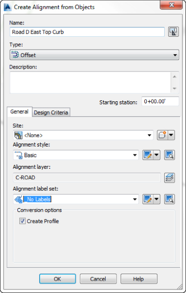
Figure 9.24 The completed Create Alignment From Objects dialog
- Click OK to accept the settings in the Create Alignment From Objects dialog and display the Create Profile – Draw New dialog.
- In the Name text box of the Create Profile – Draw New dialog, name the profile FG-Road D East Top Curb.
- On the General tab of the Create Profile – Draw New dialog, verify that the profile style is set to Design Profile and that the profile label set is set to _No Labels.
The dialog should match Figure 9.25.
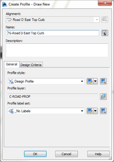
Figure 9.25 The Create Profile – Draw New dialog
- Click OK to accept the settings in the dialog and then press ↲ to exit the command. If corridor is still selected, press Esc to deselect.
- In Prospector, expand Alignments Offset Alignments Road D East Top Curb Profiles to review the completed alignment and profile (see Figure 9.26).
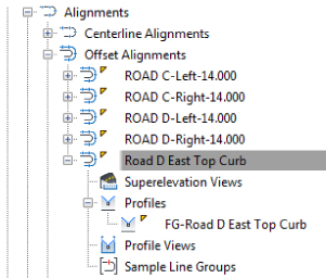
Figure 9.26 The completed alignment and profile shown on the Prospector tab of Toolspace
There are additional offset alignments listed on Prospector that were created to construct the intersection of Road C and Road D. You will be learning about intersections in the next chapter.
Next, you will extract a corridor feature line and keep it dynamically linked to the corridor.
- From the Home tab Create Design panel, choose Feature Line Create Feature Line From Corridor.

Alternatively, you can select the corridor by selecting the corridor feature line that you want to create a feature line from to activate the Corridor contextual tab and then selecting Feature Lines From Corridor from the Launch Pad panel. If you do this, then skip the next step.
- At the
Select a corridor feature line:prompt, select the feature line labeled in the drawing as DAYLIGHT FEATURE LINE.This opens the Select A Feature Line dialog, similar to the one shown in Figure 9.27.
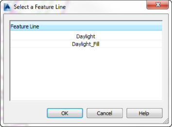
Figure 9.27 Selecting the Daylight feature line with the Select A Feature Line dialog
The Select A Feature Line dialog will open when there are overlapping feature lines available at the location selected.
- Select the Daylight feature line from the Select A Feature Line dialog.
- Click OK to close the Select A Feature Line dialog and display the Create Feature Line From Corridor dialog.
- Select the Name check box and name the feature line Road D Daylight East.
- Verify that Style is set to Corridor Grading.
- Verify that the Create Dynamic Link To The Corridor check box is selected.
All other settings can be left at their defaults. The dialog should match Figure 9.28.
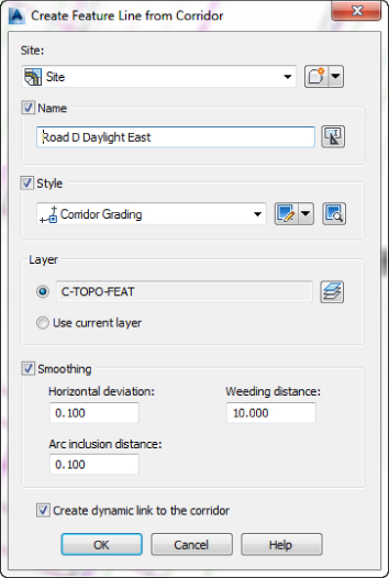
Figure 9.28 The Create Feature Line From Corridor dialog with the option to create a dynamic link turned on
- Click OK to accept the settings in the dialog and then press ↲ to exit the command. If the corridor is still selected, press Esc to deselect.
- Select the newly created auto corridor feature line.
Note that it can be selected but does not have grips.
- From the Feature Line contextual tab Modify panel, click the Edit Geometry and Edit Elevations buttons to reveal these hidden panels if they are not displaying.
Note which options on the contextual tab are grayed out and which are not, as shown in Figure 9.29.

Figure 9.29 Auto Corridor Feature Line contextual tab
These alignments and feature lines can now be used for further design. Remember that feature lines created from the corridor but not dynamically linked to the corridor are no longer connected to the corridor and will not update as you make modifications to the corridor.
When this exercise is complete, you can close the drawing. A finished copy of this drawing is available from the book's web page with the filename 0902_CorridorFeatureLine_FINISHED.dwg or 0902_CorridorFeatureLine_METRIC_FINISHED.dwg.
Understanding Targets
Every subassembly is programmed with parameters. Some of these parameters are fixed values like pavement thickness. A lot of subassemblies are programmed with targeting parameters. Examples of targeting parameters would be lane width and cross slope. Lane width and cross slope can be variable. Therefore, if this is the case, you could use alignment and profile targets to define the variable lane width and cross slope.
Alignments, profiles, feature lines, survey figures, and polylines can be configured as targets for subassemblies with width or cross slope. Surface targets are used with daylighting and roadway rehabilitation subassemblies. Ever since the release of Civil 3D 2014, you can select these targets through external references. Not all subassemblies contain targeting parameters. You can refer to the help file for target information regarding any subassembly you plan to use.
When you built the corridor in the first exercise, the opening dialog prompted you for a surface target. Next we will cover linear targets.
Using Target Alignments and Profiles
So far, the corridor examples you looked at have a constant cross section. In this section, we'll take a look at what happens when a portion of your corridor needs to transition to a wider section and then transition back to normal.
Many subassemblies have been programmed to allow for not only a baseline attachment point but also additional outer attachment points that can target alignments, feature lines, and profiles. Be sure to check the subassembly help file to make sure the subassembly you are using will accept targets if you need them. In Chapter 8, you learned that you can right-click any subassembly in the Tool Palettes window to enter the help file. For instance, the BasicLane subassembly will show None in the Target Parameters area of the help file, but LaneSuperElevationAOR lists Lane Width and Outside Elevation.
Think of a subassembly as a rubber band that is attached both to the baseline of the corridor (such as the road centerline) and to the target alignment. As the target alignment, such as a lane widening, gets further from the baseline, the rubber band is stretched wider. As that target alignment transitions back toward the baseline, the rubber band changes to reflect a narrower cross section.
Figure 9.30 shows what happens to a cross section when various targets are set for the left edge of a traveled way for a lane subassembly. Figure 9.30a shows the assembly as it was originally placed in the drawing. The width from the original assembly is 14' with a cross slope of 2 percent to the edge of pavement. Figure 9.30b shows how the geometry changes if an alignment target is set for the edge of pavement. Notice that because there is no profile specified to change the elevation, the 2 percent cross slope is held and the lane width is the only geometry that changes. Figure 9.30c shows that if both an alignment and profile are specified for an edge of pavement alignment, the design cross slope and width both change. Last, you see the assembly with just a profile target assigned to the edge of pavement in Figure 9.30d. In this case, the width stays at 14', but the elevation of the edge of pavement is dictated by the profile.
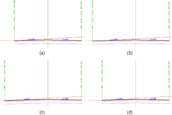
Figure 9.30 How geometry changes with a target on the left: original assembly geometry (a), assembly with width alignment target only (b), assembly with both alignment and profile target (c), and assembly with only profile target set (d)
The following exercise shows you how to set targets using an offset alignment with a widening configured to build a right turn lane in the corridor:
- Open the
0903_TargetPractice.dwgor0903_TargetPractice_METRIC.dwgfile. Note that this drawing has an incomplete corridor.You will be creating an offset alignment and modifying the alignment with a widening. Then you will use the Target Mapping dialog to configure the outer lane edge to follow the alignment.
- From the Home tab Create Design panel, choose Alignment Create Offset Alignment.

- At the
Select an alignment:prompt, select the ROAD D alignment.You might need to pan toward where it intersects ROAD A to avoid a selection conflict with the corridor.
- In the Create Offset Alignments dialog, configure the following:
- No Of Offsets On Left: 0
- No Of Offsets On Right: 1
- Incremental Offset On Right: 14' (4.5 m)
- Alignment Style: Offsets
- Alignment Label Set: _No Labels
- Click OK to dismiss.
The offset alignment has been created. Notice how it lines up with the right edge of pavement in Figure 9.31.
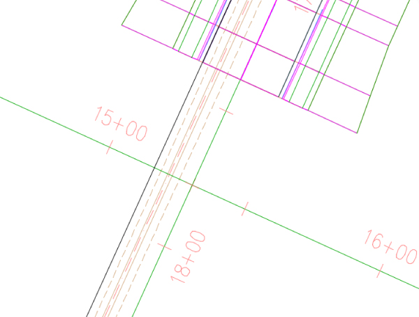
Figure 9.31 Offset Alignment representing the edge of pavement before adding a widening
In the previous exercise, you created an alignment from a feature line in the corridor. The difference between an alignment from a corridor and an offset alignment is that the offset alignment remains dynamic to the centerline alignment. If the centerline alignment geometry changes, the offset alignment geometry will change with it, maintaining its offset value.
- From the Home tab Create Design panel, choose Alignment Create Widening.

- At the
Select an alignment:prompt, select the new offset alignment. - At the
Create widening portion as a new alignment:prompt, enter No. - At the
Select start station:prompt, type 1638 ↲ (or 502 ↲ for metric users). - At the
Select end station:prompt, type 1738 ↲ (or 527 ↲ for metric users). - At the
Enter widening offset:prompt, type 28 ↲ (or 9 ↲ for metric users), the offset distance from the centerline alignment to the widening alignment.The Offset Alignment Parameters palette appears as shown in Figure 9.32. Though you won't be making any changes to the defaults at this time, observe that you can change or extend the transition parameters at the entry and exit if desired.
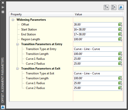
Figure 9.32 Offset Alignment Parameters palette
- Dismiss the Offset Alignment Parameters palette by clicking the X in the upper corner.
- Select the corridor to activate the Corridor contextual tab.
- From the Corridor contextual tab Modify Corridor panel, choose the Corridor Properties icon.
- On the Parameters tab, locate the baseline named BL - ROAD D - (13) for Imperial and metric units.
There are multiple baselines in this corridor. As mentioned earlier in the chapter, a corridor can contain multiple baselines and baselines can contain multiple regions.
- In the Target column for region RG - Urban 14' Single-Lane - (6) (for Imperial units) or RG - Urban 4.5m Single-Lane - (2) (for metric units), click the ellipsis button to display the Target Mapping dialog. You may need to make the Name column wider to see the row name.
- In the Width Or Offset Targets Width Alignment branch for Lane SuperelevationAOR for the Right Assembly Group, click <None> to display the Set Width Or Offset Target dialog.
New to Civil 3D 2016 is the Alignments Bylayer feature, shown in this dialog.
- With the Select Object Type To Target drop-down set to Alignments, use the Select From The Drawing button to select the offset alignment that you just created.

- Press Enter when finished selecting to return to the Set Width Or Offset Target dialog.
- Click the Add button.
The alignment should appear in the listing of selected entities to target at the bottom of the dialog, as shown in Figure 9.33.
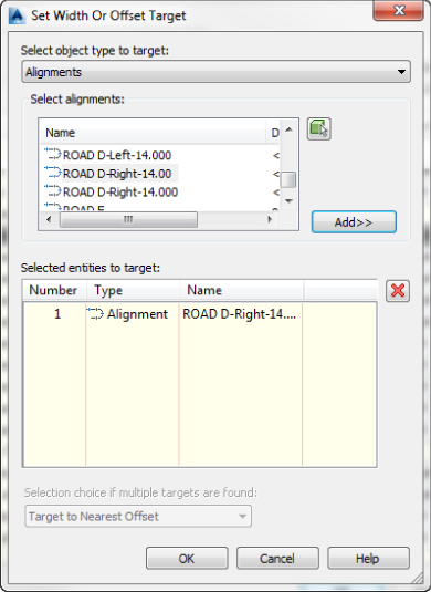
Figure 9.33 The Set Width Or Offset Target dialog
- Click OK to accept the settings in the Set Width Or Offset Target dialog.
The Target Mapping dialog should now look like Figure 9.34.
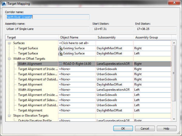
Figure 9.34 Targets set for surface and lane width for the right side
- Click OK to accept the settings in the dialog
- Click OK to accept the settings in the Corridor Properties dialog and allow the corridor to rebuild.
The corridor should now be following the ETW alignment and resemble Figure 9.35.
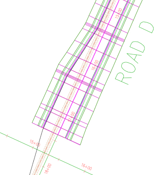
Figure 9.35 The completed exercise in plan view
A finished copy of this drawing is available from the book's web page (0903_TargetPractice_FINISHED.dwg or 0903_TargetPractice_METRIC_FINISHED.dwg).
Editing Sections
Once your corridor is built, chances are you will want to examine it section by section, make some adjustments, and check for problems. For a station-by-station look at a corridor, select the corridor and from the Corridor contextual tab ![]() Modify Corridor Sections panel, choose Section Editor (see Figure 9.36).
Modify Corridor Sections panel, choose Section Editor (see Figure 9.36).
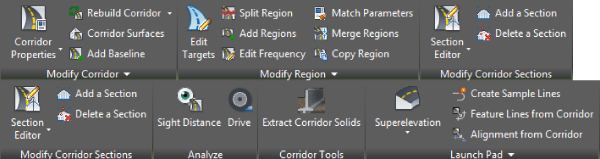
Figure 9.36 Some of the many tools, including the Section Editor, available on the Corridor contextual tab
Once you are in the Section Editor, you are in a purely data-driven view. That means that this is a live, editable section of the corridor and is not for plotting purposes. We will discuss plotting cross sections in Chapter 12, “Cross Sections and Mass Haul.”
The Section Editor allows for multiple viewport configurations so that you can see the plan, profile, and section all at the same time, as demonstrated in the following exercise:
- Open the
0904_CorridorFrequency_FINISHED.dwgor0904_CorridorFrequency_METRIC_FINISHED.dwgfile. - Select the corridor, and from the Corridor contextual tab Modify Corridor Sections panel choose Section Editor.
- From the Section Editor contextual tab View Tools panel, choose Viewport Configuration to display the Corridor Section Editor: Viewport Configuration dialog, as shown in Figure 9.37.
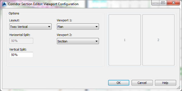
Figure 9.37 The Corridor Section Editor: Viewport Configuration dialog
- Set Layout to Three: Above and Viewport 1 to Plan, Viewport 2 to Profile, and Viewport 3 to Section with a 50 percent horizontal split and a 50 percent vertical split.
- Click OK to accept the settings in the Viewport Configuration dialog. Your screen should now look similar to Figure 9.38.
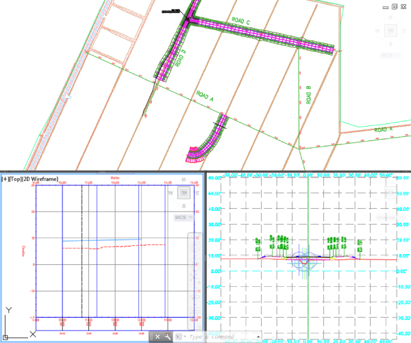
Figure 9.38 The Corridor Section Editor with Viewport Configuration set to Three: Above
- You may receive a warning dialog asking if you would like to turn on Viewport Configuration; if so, select Yes.
- To exit the Section Editor, click the Close button on the Close panel.
- Close the drawing. You don't need to save changes.
The Section Editor contextual tab offers many commands other than just Viewport Configuration, as shown in Figure 9.39.
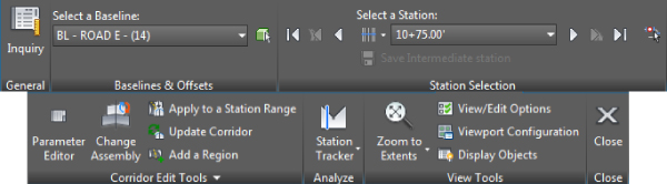
Figure 9.39 The Corridor Section Editor contextual tab
The Station Selection panel on the Section Editor contextual tab allows you to move forward and backward through your corridor to see what each section looks like. For complex corridors, you can switch between baselines.
If you want to edit a section, you may do so geometrically in the viewport showing the section in the Section Editor or through the Parameter Editor palette but not both. To graphically edit a link, hold down the Ctrl key on the keyboard while selecting the item. This will activate grips that you can use to relocate or stretch the link (Figure 9.40).
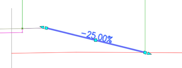
Figure 9.40 A Daylight link ready for grip-editing in the Section Editor
If you would rather use the Parameter Editor to make more precise changes to your section, do the following:
- From the Section Editor contextual tab Corridor Edit Tools panel, choose Parameter Editor.
- Advance the Select A Station list until you reach the station of interest.
The Parameter Editor button will not be active for stations without an assembly applied.
- Look through the listing of subassemblies and their current parameter values.
- When you find a value you want to edit, click in the Value field to override the design value, as shown in Figure 9.41.
When you change the value, a check mark will appear in the Override column. You will find that some of the values are uneditable.
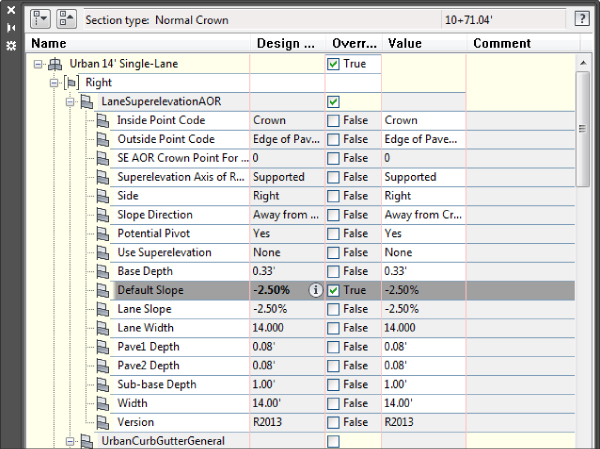
Figure 9.41 The Corridor Parameter Editor
The changes you make can be applied to just the section you are viewing or to a range of stations in the region you are working in (use the Apply To A Station Range button in the Corridor Edit Tools panel to apply the changes to a region).
Creating a Corridor Surface
A corridor provides the raw components for surface creation. Just as you would use points, breaklines, and boundaries to make a surface, a corridor surface uses corridor points as point data, feature lines and links as breaklines, and various commands for using corridor geometry as an outer boundary.
The Corridor Surface
Civil 3D does not automatically build a corridor surface when you build a corridor. From examining subassemblies, assemblies, and the corridors you built in the previous exercises, you have probably noticed that there are many “layers” of points, links, and feature lines. Some represent the top of the finished ground of your road design, some represent subsurface gravel or concrete thicknesses, and some represent subgrade, among other possibilities. You can choose to build a surface from any one of these layers or from all of them. Figure 9.42 shows an example of a TIN surface built from the links that are coded Top, which would represent final finished ground.
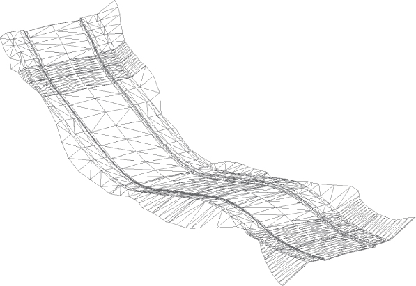
Figure 9.42 A surface built from Top code links
When you create a surface from a corridor, the surface is dependent on the Corridor object. This means that if you change something about your corridor and then rebuild the corridor, the surface will also update.

A corridor surface shows up as a surface under the Surfaces branch in Prospector with a slightly modified icon that denotes it is related to the corridor.

After you create the initial corridor surface, you can create a static export of the surface by changing to the Home tab ![]() Create Ground Data panel and choosing Surfaces
Create Ground Data panel and choosing Surfaces ![]() Create Surface From Corridor. The Create Corridor Surfaces dialog will appear. If you have created multiple surfaces inside multiple corridors, all of the surfaces will be listed. Fill the check box next to each surface to be exported and then click OK. A detached surface will not react to corridor changes and can be used to archive a version of your surface. To remind you that this surface is not related to a corridor, the icon in the Surfaces branch in Prospector will not show the corridor icon.
Create Surface From Corridor. The Create Corridor Surfaces dialog will appear. If you have created multiple surfaces inside multiple corridors, all of the surfaces will be listed. Fill the check box next to each surface to be exported and then click OK. A detached surface will not react to corridor changes and can be used to archive a version of your surface. To remind you that this surface is not related to a corridor, the icon in the Surfaces branch in Prospector will not show the corridor icon.
Corridor Surface Creation Fundamentals
You create corridor surfaces on the Surfaces tab in the Corridor Properties palette using the following three steps (which are examined in detail later):
- Click the Create A Corridor Surface button to add a surface item.

- Choose the data type, either links or feature lines.
- Choose the data to add and click the Add Surface Item button.

You can choose to create your corridor surface on the basis of links, feature lines, or a combination of both.
Creating a Surface from Link Data
Most of the time, you will build your corridor surface from links. As discussed earlier, each link in a subassembly is coded with a name such as Top, Pave, Datum, and so on. Choosing to build a surface from Top links will create a surface that triangulates between the points at the link vertices that represent the final finished grade.
The most commonly built link-based surfaces are Top for contours and Datum for earthworks; however, you can build a surface from any link code in your corridor. Figure 9.43 shows a schematic of how links are used to form the most common surfaces—in this case a top surface, as shown in the top image of Figure 9.43, and a datum surface, as shown in the bottom image of Figure 9.43.
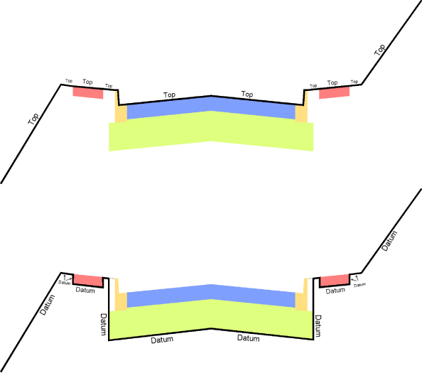
Figure 9.43 Schematic of Top links connecting to form a surface (top) and schematic of Datum links connecting to form a surface (bottom) [c09f043.eps]
When building a surface from links, you have the option of checking a box in the Add As Breakline column. Checking this box will add the actual link lines themselves as additional breaklines to the surface. In most cases, especially in intersection design, checking this box forces better triangulation.
Creating a Surface from Feature Lines
There might be cases where you would like to build a simple surface from your corridor—for example, by using just the crown and edge-of-travel way. If you build a surface from feature lines only or a combination of links and feature lines, you have more control over what Civil 3D uses as breaklines for the surface.
If you added all the topmost corridor feature lines to your surface item and built a surface, you would get a result that's similar to the result you would get if you had added the Top link codes.
Creating a Surface from Both Link Data and Feature Lines
A link-based surface can be improved by the addition of feature lines. A link-based surface does not automatically include the corridor feature lines but instead uses the link vertex points to create triangulation. Therefore, the addition of feature lines ensures that triangulation occurs where desired along ridges and valleys. This is especially important for intersection design, curves, and other corridor surfaces where triangulation around tight corners is critical. Figure 9.44 shows the Surfaces tab of the Corridor Properties dialog where a Top link surface will be improved by the addition of Back_Curb, ETW, and Top_Curb feature lines.
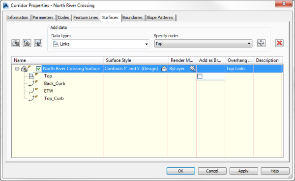
Figure 9.44 The Surfaces tab indicates that the surface will be built from Top links as well as from several feature lines.
If you are having trouble with triangulation or contours not behaving as expected, experiment with adding a few feature lines to your corridor surface definition.
Creating a Corridor Surface for Each Link

To the right of the Create Corridor Surface button is the Create A Corridor Surface For Each Link button. Clicking this button populates the Surface List area with a multitude of corridor surfaces; as the button name would suggest, you will now have a corridor surface for each of the link codes.

This may not be desirable for many people because you rarely need a surface for every link, but once they are created, you can always remove the unwanted corridor surfaces using the Delete Surface Item button.
Using the Corridor Surface Name Template

The third button at the upper left of the Surfaces tab of the Corridor Properties dialog is the Surface Name Template button. When you click this button, the Name Template dialog shown in Figure 9.45 appears.
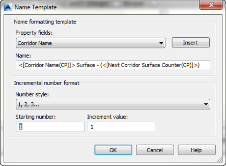
Figure 9.45 The Name Template dialog for corridor surfaces
Here you can set the formatting for the corridor name as well as the number style, starting number, and increment value. The Property fields are Corridor Name and Next Corridor Surface Counter. Based on the name shown in Figure 9.45, the next surface created for the corridor named North River Crossing will be named North River Crossing Surface – (1). The Number style can be set to 1, 2, 3 … or 01, 02, 03 … or a multitude of other styles based on the number of leading zeros.
Completing Other Surface Tasks
You can do several other tasks on the Surfaces tab. For each corridor surface, you can set a surface style, revise the default name assigned by the Name Template, and provide a description for your corridor surface. Alternatively, you can do all those things once the corridor surface appears under the Surface branch in Prospector.
Adding a Surface Boundary
Surface boundaries are critical to any surface but especially so for corridor surfaces. Tools that automatically and interactively add surface boundaries, using the corridor intelligence, are available. Figure 9.46 shows a corridor surface before and after the addition of a boundary. Notice how the extraneous contours have been eliminated along the line of intersection between the existing ground and the proposed ground (the daylight line), thereby creating a much more accurate surface.
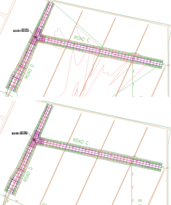
Figure 9.46 A corridor surface before the addition of a boundary (top) and after the addition of a boundary (bottom)
You can create corridor surface boundaries using the Boundaries tab of the Corridor Properties dialog. Each corridor surface will be listed. To add the boundary, right-click the corridor surface and select the desired boundary type.
Boundary Types
There are several tools to assist you in corridor surface boundary creation. They can be automatic, semiautomatic, or manual in nature, depending on the complexity of the corridor.
You access these options on the Boundaries tab of the Corridor Properties dialog by right-clicking the name of your surface item, as shown in Figure 9.47.
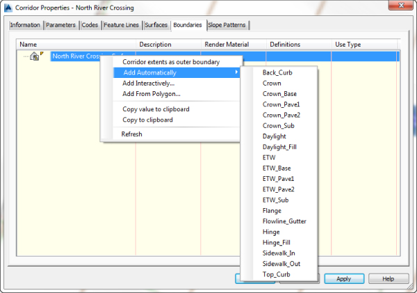
Figure 9.47 Corridor surface boundary options for a corridor containing a single baseline
The following corridor boundary methods are listed in order of desirability. Corridor Extents As Outer Boundary is the most user-friendly, whereas Add From Polygon is fast but needs constant updating because it is not dynamically linked to the corridor.
- Corridor Extents As Outer Boundary With this selection, Civil 3D will shrink-wrap the corridor, taking into account intersections and various daylight options on different alignments. Corridor Extents As Outer Boundary will probably be your most-used boundary option unless you are modeling other parts of your roadway network in separate corridors. This topic will be covered in more detail in Chapter 10.
- Add Automatically The Add Automatically boundary tool allows you to pick a point code and use the associated feature lines as your corridor boundary. This tool is available only for single-baseline corridors. This tool is automatic, is easy to apply, and will remain dynamically linked to the corridor.
- Add Interactively The Add Interactively boundary tool allows you to work your way around a corridor and choose which corridor feature lines you would like to use as part of the boundary definition.
Choosing this option is better than using Add From Polygon if Add Automatically and Corridor Extents are not available. This method is also good for defining hide boundaries in your corridor surface (hide boundaries were discussed in Chapter 4, “Surfaces”). It takes a bit of patience to trace the corridor, but the result is a dynamically linked boundary that changes when the corridor changes. Using this method, once you select a feature line, a thick line will trace around the corridor following your mouse; to switch to a different feature line, simply click the new feature line at the transition location. When it's complete, you can close the boundary just as you would a polyline.
- Add From Polygon The Add From Polygon tool allows you to choose a closed 2D or 3D polyline or polygon in your drawing that you would like to add as a boundary for your corridor surface. This method is quick, but unlike the other methods, the resulting boundary is not dynamic to your design.
The next exercise leads you through creating a corridor surface with a shrink-wrap and an interactive boundary:
- Open the
0905_CorridorBoundary.dwgor0905_CorridorBoundary_METRIC.dwgfile. - Select the corridor to activate the Corridor contextual tab.
- From the Corridor contextual tab Modify Corridor panel, choose the Corridor Properties icon.
- On the Surfaces tab of the Corridor Properties dialog, click the Create A Corridor Surface button in the upper-left corner of the dialog.

You should now have a surface item in the bottom half of the dialog.
- Click the surface item under the Name column and change the default name of your surface to North River Crossing - Top.
- Verify that Links has been selected from the drop-down list in the Data Type selection box.
- Verify that Top has been selected from the drop-down list in the Specify Code selection box.
- Click the Add Surface Item button to add Top Links to the Surface Definition, set the Overhang Correction to Top Links, and fill in the Add As Breakline check box.

- Click OK to accept the settings in this dialog. Choose Rebuild The Corridor when prompted and examine your surface.
The road surface should look fine; however, because you have not yet added a boundary to this surface, undesirable triangulation is occurring outside your corridor area and the area bounded by ROAD A, B, C, and D.
- Expand the Surfaces branch in Prospector.
Note that you now have a corridor surface listed in addition to the existing surface that was already in the drawing.
- Select the corridor again to activate the Corridor contextual tab if not already selected.
- From the Corridor contextual tab Modify Corridor panel, choose Corridor Properties icon.
If you do not see the Corridor Properties button on the Modify Corridor panel, you may have inadvertently chosen the corridor surface and may be viewing the Surface contextual ribbon.
- On the Boundaries tab of the Corridor Properties dialog, right-click North River Crossing – Top in the listing.
- Select Corridor Extents As Outer Boundary, which will define the outer boundary of the surface.
- Click OK to accept the settings in the Corridor Properties dialog, and choose Rebuild The Corridor when prompted.
- Examine your surface, and note that the triangulation terminates at the outer limits of the corridor.
- Select the corridor again to activate the Corridor contextual tab if not still selected.
- From the Corridor contextual tab Modify Corridor panel, choose the Corridor Properties icon.
- On the Boundaries tab of the Corridor Properties dialog, right-click North River Crossing – Top in the listing.
- Select Add Interactively.
The Corridor Properties dialog will temporarily disappear while you define this boundary. You will now digitize around the area enclosed by ROAD A, B, C, and D, tracing over the edge of the corridor defining the enclosed area. You may find it helpful to turn on your endpoint Osnap setting, but it isn't necessary.
- Using your scroll button, zoom into the northwest corner of the intersection of ROAD A and ROAD B.
Be careful to avoid exiting the command while doing so.
- Pick the edge of the corridor. If you see the Select A Feature Line dialog open, select Edge and click OK.
- Drag the cursor to the left along the edge of the corridor until you see a red, dashed line representing your interactive boundary beginning to trace over the Edge feature line, as shown in Figure 9.48.
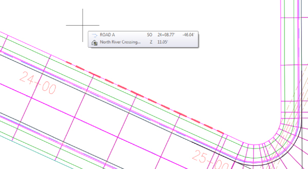
Figure 9.48 Defining an interactive boundary
- Pan to the left along the edge of the corridor until the red, dashed line makes a stop.
It will make a stop when it reaches another baseline.
- Click the stopping point and then click the link ahead of the stopping point to continue the generation of the interactive boundary.
- Repeat step 25 whenever the interactive boundary makes a stop until you reach the point of closing your boundary.
If you accidentally click the wrong location, just type U for undo to redefine the last segment. If the interactive boundary doesn't want to follow the edge of your corridor in certain areas, click the link the edge at the location just before the bad behavior begins. If the Select A Feature Line dialog opens displaying two Edge feature lines, just pick the top one and click OK.
- To close your boundary, click the link just before the start point and type C for close.
The Corridor Properties dialog will reappear.
- On the Boundary tab of the Corridor Properties dialog, there are two boundaries listed.
- Select Corridor Boundary(2) and click in the Use Type column to change the setting to Hide Boundary, as shown in Figure 9.49.
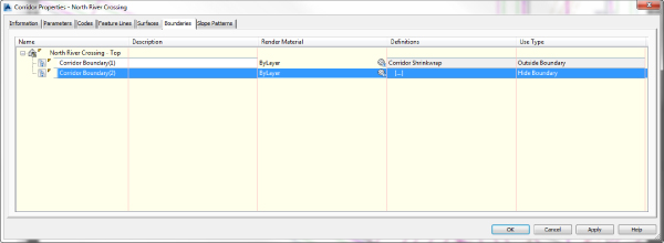
Figure 9.49 Configuring the interactive boundary as a Hide boundary
- Click OK to dismiss the Corridor Properties dialog. Rebuild the corridor if prompted.
- (Optional) Experiment with making changes to your finished grade profile, assembly, or alignment geometry and rebuilding both your corridor and finished ground surface to see the boundary in action.
When this exercise is complete, you can close the drawing. A finished copy of this drawing is available from the book's web page with the filename 0905_CorridorBoundary_FINISHED.dwg or 0905_CorridorBoundary_METRIC_FINISHED.dwg.
Common Surface-Creation Problems
Here are some common problems you may encounter when creating surfaces:
- Problem Your corridor surface does not appear or seems to be empty.
- Typical Cause You might have created the surface item but not added any data. Another cause could be the surface style is set to No Display or to display contours at a wide interval, or the surface was created on a frozen layer.
- Fix Open the Corridor Properties dialog and switch to the Surfaces tab. Select a data type from the drop-down menus in the Data Type and Specify Code selection boxes, and click the Add Surface Item button. Make sure your dialog shows both a surface item and a data type, as shown in Figure 9.50.
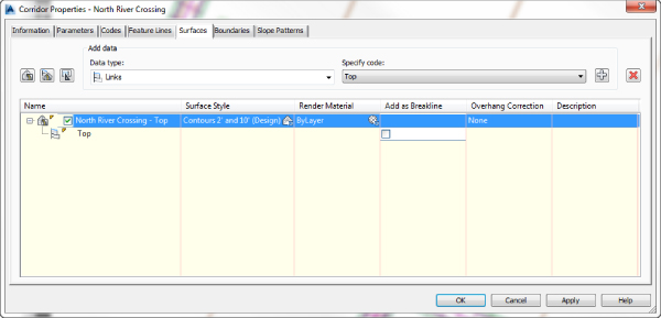
Figure 9.50 A surface cannot be created without both a surface item and a data type.
- Problem Your corridor surface does not seem to respect its boundary after a change to the assembly or surface-building data type (in other words, you switched from link data to feature lines).
- Typical Cause Automatic and interactive boundary definitions are dependent on the codes used in your corridor. If you remove or change the codes used in your corridor, the boundary needs to be redefined.
- FixOpen the Corridor Properties dialog and switch to the Boundaries tab. Remove any boundary definitions that are no longer valid (if any) by right-clicking the boundary and selecting Remove Boundary. Once the outdated boundary has been removed, you can redefine the corridor surface boundaries using any of the applicable boundary types.
- Problem Your corridor surface seems to have gaps at points of curvature (PCs) and points of tangency (PTs) near curb returns.
- Typical Cause You may have encountered an error in rounding station values at these locations and as a result created gaps in your corridor. This is commonly caused by osnapping to start and end region stations using two-dimensional linework as a guide when some segments of that linework do not touch.
- Fix Be sure your corridor region definitions produce no gaps. You might consider using the
PEDITcommand to join lines and curves representing corridor elements that will need to be modeled later. You might also consider setting a COGO point at these locations (PCs, PTs, and so on) and using the Node object snap instead of the Endpoint object snap to select the same location each time you are required to do so.
Performing a Volume Calculation
One of the most powerful aspects of Civil 3D is having instant feedback on your design iterations. Once you create a preliminary road corridor, you can immediately compare a corridor surface to existing ground and get a good understanding of the earthwork magnitude. When you make an adjustment to the finished grade profile and then rebuild your corridor, you can see the effect that this change has on your earthwork within minutes, if not sooner.
Even though volumes were covered in detail in Chapter 4, it is worth revisiting the subject here in the context of corridors.
This exercise uses a TIN-to-TIN composite volume calculation to compare the existing ground surface and the datum corridor surface; average end area and other section-based volume calculations are covered in Chapter 12.
- Open the
0906_CorridorVolume.dwgor0906_CorridorVolume_METRIC.dwgfile.Note that this drawing has a completed North River Crossing corridor, as well as a top corridor surface and a datum corridor surface.
- From the Analyze tab Volumes And Material panel, choose Volumes Dashboard to display the Volumes Dashboard tab in the Panorama.

- Click the Create New Volume Surface button to display the Create Surface dialog.

- Change the name to Vol - Road Datum and set Style to Elevation Banding (2D).
- Click the <Base Surface> field to display the ellipsis button; once it's visible, click the ellipsis button to select Existing Surface. Then click OK.
- Click the <Comparison Surface> field to display the ellipsis button.
- Once it's visible, click the ellipsis button to select North River Crossing – Datum and then click OK.
- Click OK to accept the settings in the Create Surface dialog.
A Cut/Fill breakdown should appear in the Volumes Dashboard tab of Panorama, as shown in Figure 9.51. Your numbers may vary.
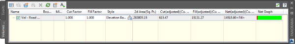
Figure 9.51 Panorama showing an example of a volume surface and the cut/fill results
- Make a note of these numbers.
- Leave Panorama open on your screen (make it smaller, if desired), and pan over to the proposed profile for Road D.
- Select the Finished Ground profile and move the vertical triangular grip on the second PVI to the center of the circle shown in the profile view.
Notice that the volume calculations have changed to Out Of Date because the corridor isn't set to rebuild automatically.
- In Prospector, expand Corridors, select the North River Crossing corridor, right-click, and choose Rebuild.
Notice that the corridor changes, and therefore the corridor surfaces (which are both set to Rebuild Automatic) change as well. However, the volume surface did not automatically rebuild.
- On the Volumes Dashboard tab of Panorama, right-click the volume surface and select Rebuild.
Notice the new values for cut and fill.
- Close Panorama using the X in the upper corner.
When this exercise is complete, you can close the drawing. A finished copy of this drawing is available from the book's web page with the filename 0906_CorridorVolume_FINISHED.dwg or 0906_CorridorVolume_METRIC_FINISHED.dwg.
Building Nonroad Corridors
As discussed in the beginning of this chapter, corridors are not just for roads. Once you have the basics about corridors down, your ingenuity can take hold.
Corridors can be used for far more than just road designs. You will explore some more advanced corridor models in Chapter 10, but there are plenty of simple, single-baseline applications for alternative corridors such as channels, berms, retaining walls, duct banks and more. You can take advantage of several specialized subassemblies or build your own custom assembly using the Subassembly Composer. Figure 9.52 shows an example of a channel corridor.
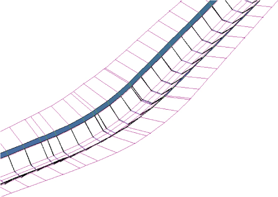
Figure 9.52 A simple channel corridor, viewed in 3D, built from the channel subassembly and a generic link subassembly
One of the subassemblies discussed in Chapter 8 is the channel subassembly. The following exercise shows you how to apply this subassembly to design a simple drainage channel:
- Open the
0907_CorridorChannel.dwgor0907_CorridorChannel_METRIC.dwgfile.Note that there is an alignment that represents a drainage channel centerline, a profile that represents the drainage channel normal water line, and an assembly created using the Channel and LinkSlopetoSurface subassemblies.
- From the Home tab Create Design panel, choose Corridor to display the Create Corridor dialog.
- In the Name text box, name your corridor Drainage Channel.
Keep the default values for Corridor Style and Corridor Layer.
- Verify that Alignment is set to Channel CL and Profile is set to Channel NWL.
NWL stands for normal water level.
- Verify that Assembly is set to Project Channel.
- Verify that Target Surface is set to Existing Ground.
- Verify that the Set Baseline And Region Parameters check box is checked.
- Click OK to accept the settings in the Create Corridor dialog and to display the Baseline And Region Parameters dialog.
- Click the Set All Frequencies button.
- Change the values for Along Tangents and Curve Increment to 10' (3 m for metric users).
- Click OK to accept the settings in the Frequency To Apply Assemblies dialog.
- Click OK to accept the settings in the Baseline And Region Parameters dialog.
- You may receive a dialog warning that the corridor definition has been modified. If you do, select the Rebuild The Corridor option.
- Select the corridor to activate the contextual tab.
- From the Corridor contextual tab Modify Corridor Sections panel, choose Section Editor.
- From the Section Editor contextual tab Station Selection panel, you can navigate through the drainage channel cross sections by clicking the forward and backward arrows.
The cross section should look similar to Figure 9.53.
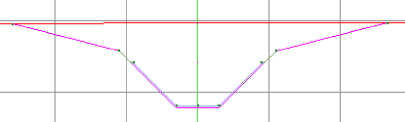
Figure 9.53 The completed Drainage Channel corridor viewed in the Section Editor
This corridor can be used to build a surface for a TIN-to-TIN volume calculation or to create sections and generate material quantities, cross-sectional views, and anything else that can be done with a more traditional road corridor.
When you are finished viewing the sections, dismiss the dialog by clicking the X on the Section Editor contextual tab ![]() Close panel. When this exercise is complete, you can close the drawing. A finished copy of this drawing is available from the book's web page with the filename
Close panel. When this exercise is complete, you can close the drawing. A finished copy of this drawing is available from the book's web page with the filename 0907_CorridorChannel_FINISHED.dwg or 0907_CorridorChannel_METRIC_FINISHED.dwg.
The Bottom Line
- Build a single baseline corridor from an alignment, profile, and assembly. Corridors are created from the combination of alignments, profiles, and assemblies. Although corridors can be used to model many things, most corridors are used for road design.
- Master It Open the
MasterIt_0909.dwgorMasteringIt_0909_METRIC.dwgfile. Build a corridor named Corridor A on the basis of the Alignment A alignment, the FG profile, and the Basic Assembly. Set EG as the target surface. Set all frequencies to 10' (or 3 m for metric users).
- Master It Open the
- Use targets to add lane widening. Targets are an essential design tool used to manipulate the geometry of the road.
- Master It Open the
MasterIt_0910.dwgorMasterIt_0910_METRIC.dwgfile. Set Right Lane to target Alignment A-Right.
- Master It Open the
- Create a corridor surface. The corridor model can be used to build a surface. This corridor surface can then be analyzed and annotated to produce finished road plans.
- Master It Open the
MasterIt_0911.dwgorMasterIt_0911_METRIC.dwgfile. Create a corridor surface for the Alignment A corridor from Top links. Name the surface Corridor A-Top.
- Master It Open the
- Add an automatic boundary to a corridor surface. A surface can be improved with the addition of a boundary. Single-baseline corridors can take advantage of automatic boundary creation.
- Master It Open the
MasterIt_0912.dwgorMasterIt_0912_METRIC.dwgfile. Use the Automatic Boundary Creation tool to add a boundary using the Daylight code.
- Master It Open the