Chapter 17
Quantity Takeoff
The goal of every project is eventually construction. Before the first bulldozer can be fired up and the first pile of dirt moved, the owner, city, or developer has to know how much all of this paving, pipe, and dirt are going to cost. Although contractors and construction managers are typically responsible for creating their own estimates for contracts, the engineers often perform an estimate of cost to help judge and award the eventual contract. To that end, many firms have entire departments that spend their days counting manholes, running planimeters around paving areas, and measuring street lengths to figure out how much striping will be required.
The Autodesk® AutoCAD® Civil 3D® software includes a Quantity Takeoff (QTO) feature to help relieve that tedious burden. You can use the model you've built as part of your design to measure and quantify the pieces needed to turn your project from paper to reality. You can export this data to a number of formats and even to other applications for further analysis.
In this chapter, you will learn to:
- Open and add to a list of pay items.
- Assign pay items to AutoCAD objects and pipe networks.
- Use QTO tools to review what items have been tagged for analysis.
- Generate QTO output to a variety of formats for review or analysis.
Employing Pay Item Files
Before you can begin running any sort of analysis or quantity, you have to know what items you are trying to quantify. Various municipalities, states, and review agencies have their own lists of items and methods of breaking down the quantities involved in a typical development project.
There are three main files associated with quantity takeoff in Civil 3D: the pay item list, the pay item categorization file, and the formula file. Each file serves a different purpose and is stored externally to the project. Once a file has been associated to a drawing file (DWG), the path to these files is stored with the DWG.
- Pay Item List When preparing quantities, different types of measurements are used based on the items being counted. Some are simple individual objects such as light posts, fire hydrants, and manholes. Only slightly more complicated are linear objects such as road striping and area items such as grass cover. These measurements are also part of the pay item list. At minimum, the pay item list will provide you with three main pieces of information for each item:
- The pay item number
- The pay item description
- The pay item unit of measure
There are three file types allowable for the pay item list file:
- CSV (Comma Delimited)
- AASHTO TransXML
- Florida DOT
- Pay Item Categorization File In any project, there can be thousands of items to tabulate. To make this process easier, most organizations have built pay categories, and Civil 3D makes use of this system in a categorization file. Civil 3D includes an option to create favorite items that are used most frequently. This file, which is always formatted as an XML file, is optional.
- Formula File The formula file is used when the unit of measure for the pay item needs to be converted or calculated based on another value. For example, bituminous concrete for a parking lot is usually paid for by the ton, but you will generally be obtaining an area from CAD. You can set up a formula that converts square feet into tons, taking into account an assumed depth and density. Later in this chapter, you will create a formula that relates length to light poles along the road.
A command is available if you need to disconnect your pay item and formula files from the drawing. At the command line you can type DETACHQTOFILES. The Undo command will not reconnect them if you type this in accidentally.
In the next section, you will learn how to connect the needed pay item files and create favorites.
Pay Item Favorites
Your Civil 3D file will “remember” which files it needs to correctly assess quantities. The Favorites list is a separate category that can be populated for quick access to commonly used pay items. This list is saved inside the DWG.
In this exercise, you'll look at how to open a pay item and categorization files and add a few items to the Favorites list for later use:
- Create a new drawing using the _
AutoCAD Civil 3D (Imperial) NCStemplate. Metric users should use the _AutoCAD Civil 3D (Metric) NCStemplate. - From the Analyze tab
 QTO panel, choose QTO Manager (see Figure 17.1) to display the QTO Manager.
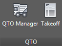
Figure 17.1 The QTO tools on the Analyze tab
- Click the Open button at the top left of the QTO Manager to display the Open Pay Item File dialog.
- In the Open Pay Item File dialog, verify that the Pay Item File Format drop-down list is set to CSV (Comma Delimited).

- Click the Open button next to the Pay Item File text box to browse for the file.
In Windows 7 and Windows 8, you can find this file in
C:\ProgramData\Autodesk\C3D 2016\enu\Data\Pay Item Data\Getting Started\.Metric users should copy the
Getting Started_METRIC.csvfile toC:\ProgramData\Autodesk\C3D 2016\enu\Data\Pay Item Data\Getting Started\, downloadable from the book's web page (www.sybex.com/go/masteringcivil3d2016). - Select the
Getting Started.CSVfile orGetting Started_METRIC.csv. - Click Open to select this CSV pay item file.
- Click the Open button next to the Pay Item Categorization File text box to browse for the file.
- Navigate back to the
Getting Startedfolder and select theGetting Started Categories.xmlfile.This file can be used by both Imperial and metric users.
- Click Open to select the file.
Your display should look similar to Figure 17.2.
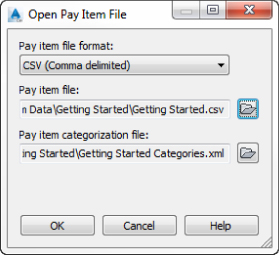
Figure 17.2 Open Pay Item File dialog
- Click OK to accept the settings in the Open Pay Item File dialog.
The QTO Manager will now be populated with a collection of divisions, as shown in Figure 17.3. These divisions came from the
Getting Started Categories.xmlfile.
Figure 17.3 The QTO Manager in Panorama populated within categories (Divisions and Groups)
- Expand the Division 200 Group 201 Section 20101 branches, and select the item 20101-0000 CLEARING AND GRUBBING. You may need to widen the Pay Item ID column.
- Right-click and select Add To Favorites List, as shown in Figure 17.4.
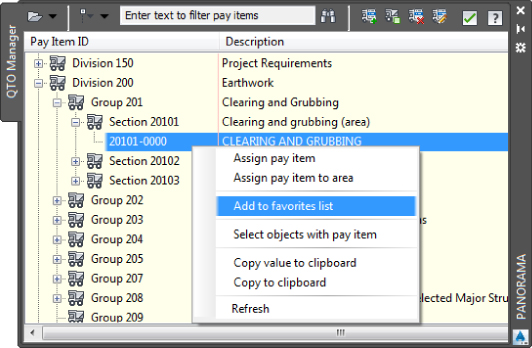
Figure 17.4 Selecting a pay item to add as a favorite
- Expand a few other branches to familiarize yourself with these pay items.
- Add the following to your Favorites list in preparation for the next exercise:
- 60404-2000 CATCH BASIN, TYPE 2
- 61106-0000 FIRE HYDRANT
- 61203-0000 MANHOLE, SANITARY SEWER
- 63401-0600 PAVEMENT MARKINGS, TYPE C, BROKEN
- Save the drawing as
1701_QTOPractice.dwgor1701_QTOPractice_METRIC.dwgand keep it open for the next exercise.When finished, scroll to the top of the Pay Item ID list and expand the Favorites category. Your QTO Manager should look similar to Figure 17.5.
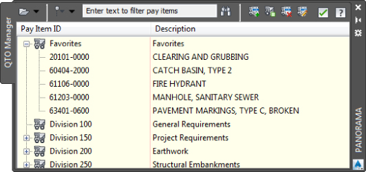
Figure 17.5 A list of favorites within the QTO Manager
Civil 3D ships with a number of pay item list categorization files but only one actual pay item list. This avoids any issue with out-of-date data. One commonly used categorization type found in the C:\ProgramData\Autodesk\C3D 2016\enu\Data\Pay Item Data\CSI\ folder is MasterFormat2004. In the United States folder, you can also find categorization files for AASHTO and Federal Highway Administration. The pay item files that install with the software are intended to be examples. Contact your reviewing agency for access to its pay item list and categorization files if they're not already part of the Civil 3D product.
Once you have pay items to choose from, it's time to assign them to your model for analysis.
Searching for Pay Items

In the top of the QTO Manager is an extremely handy filter tool. If you don't know what category an item is listed under, you can type it in the field to the left of the binoculars icon.
When you first click the binoculars icon to execute the filter, it will appear as if nothing happened. That's because the category headings are in the way of the listing. To see an uncategorized version of the list your filter produced, select Turn Off Categorization from the drop-down to the left of the filter field, as shown in Figure 17.6.
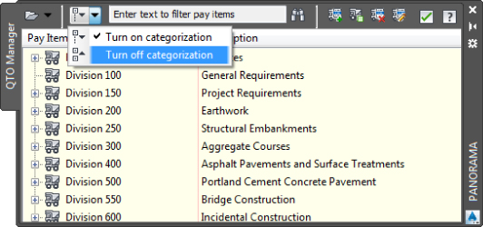
Figure 17.6 Choose Turn Off Categorization to see the results of your filter.
In the following exercise, you will use the filter functionality to add items to your Favorites list:
- If it's not still open from the previous exercise, open the
1701_QTOPractice.dwgor1701_QTOPractice_METRIC.dwgfile. You must complete the previous exercise before proceeding. - If the QTO Manager is not already open, from the Analyze tab QTO panel, choose QTO Manager to open it.

- To the left of the filter field, click the drop-down to select Turn Off Categorization.
- In the filter field of the QTO Manager, type grandi and then click the binoculars icon. You can alternatively press ↲ instead of clicking the binoculars icon.
Your filter should result in three types of trees.
- Right-click the first item, Fagus Grandifloria, and select Add To Favorites List.
- In the filter field of the QTO Manager, type Washington and then click the binoculars icon.
- Add 63620-0500 Pole, Type Washington Globe No. 16 Light Standard to the Favorites List.
You will find that by adding your most frequently used items to the Favorites list, they will be at your fingertips instead of you having to dig through branch after branch of pay items.
When this exercise is complete, you may close the drawing. A saved copy of this drawing is available from the book's web page with the filename QTOPractice_FINISHED.dwg or QTOPractice_METRIC_FINISHED.dwg.
Keeping Tabs on the Model
Once you have a list of pay items that must be quantified in your project, you have to assign these pay items to items in your drawing file. You can do so in any of the following ways:
- Assign pay items to simple AutoCAD objects such as blocks and lines.
- Assign pay items to corridor components.
- Assign pay items to pipes and structures in pipe networks.
- Assign pay items to pressure network pipes, fittings, and appurtenances.
In the next few sections, you'll explore each of these methods, along with some formula tools that can be used to convert things such as linear items to individual quantity counts.
AutoCAD Objects as Pay Items
The most basic use of the QTO tools is to assign pay items to things like blocks and linework within your drawing file. The QTO tools can be used to quantify any number of things, including tree plantings, signposts, and area items such as clearing and grubbing. In the following exercise, you'll assign pay items to blocks as well as to some closed polylines. Be sure the Getting Started.csv (or Getting Started_METRIC.csv) and Getting Started Categories.xml files are loaded as described in the first exercise.
- Open the
1703_AcadObjectsInQTO.dwgor1703_AcadObjectsInQTO_METRIC.dwgfile. - From the Analyze tab QTO panel, choose QTO Manager to display the QTO Manager.
- Expand the Favorites branch, right-click CLEARING AND GRUBBING, and select Assign Pay Item To Area, as shown in Figure 17.7.
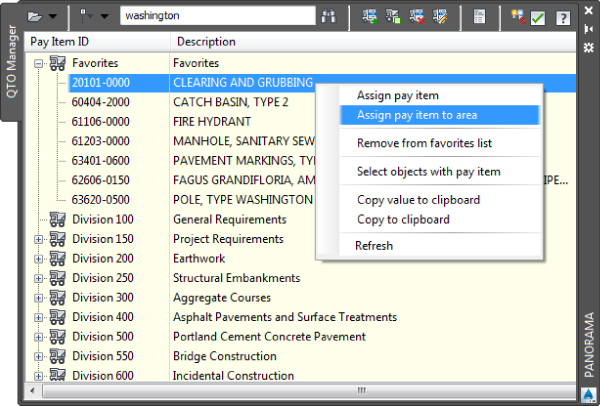
Figure 17.7 Assigning an area-based pay item
- At the
select Point or [select Object]:prompt, type O ↲ to activate the Object option for assignment. - Click the closed polyline around the outer edge of the site, as shown in Figure 17.8.
Figure 17.8 Selecting a closed polyline for an area-based quantity
Notice that the closed polyline fills with a solid hatch pattern indicating what area is being used. The command line should also echo
Pay item 20101-0000 assigned to areawhen you pick the polyline. - Press ↲ to end the command.
- Select the hatch to activate the Hatch Editor contextual tab.
- From the Hatch Editor contextual tab Properties panel, change Hatch Transparency to 90.
- Right-click the hatch and select Display Order Send To Back.
- Move the QTO Manager to the side and zoom in to the intersection of ROAD A and ROAD B where you can see one or more of the blocks representing trees.
- Select one of the tree blocks and then right-click and choose Select Similar. All of the tree blocks are selected.
- Back in the QTO Manager, under the Favorites branch, select 62606-0150 Fagus Grandifloria, American Beech.

- Near the top of the panel, click the Assign The Selected Pay Items To Object(s) In The Drawing button.
Notice the great tooltips on these buttons.
- Move your cursor over the graphics area of the drawing and press ↲ to end the assigning command.
- Repeat steps 11 through 14 to assign the pay item 61106-0000 Fire Hydrant to all of the fire hydrant blocks on the site.
When this exercise is complete, you may close the drawing. A saved copy of this drawing is available from the book's web page with the filename AcadObjectsInQTO_FINISHED.dwg or AcadObjectsInQTO_METRIC_FINISHED.dwg.
Pricing Your Corridor
The corridor functionality of Civil 3D is invaluable. You can use it to model everything from roads to streams to parking lots. With the QTO tools, you can also use the corridor object to quantify much of the project construction costs.
In this example, you'll use the pay item list along with a formula to convert the linear curb measurement to an incremental count of light poles required for the project:
- Open the
1704_QTOCorridors.dwgor1704_QTOCorridors_METRIC.dwgfile. - From the Analyze tab QTO panel, choose QTO Manager.
- Expand the Open button in the top-left corner of the QTO Manager and select Open Formula File.
- In the Open dialog, browse to the
C:\Mastering\Ch17folder and selectGetting Started Formulas.forfile. Click Open to continue. - Expand the Favorites branch to display your 63620-0500 light standard pay item.
- Widen Panorama to reveal the Formula column, and click in the Formula cell in the 63620-0500 light standard row, as shown in Figure 17.9.
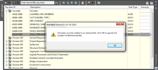
Figure 17.9 Click in the Formula cell to display this warning dialog
Civil 3D will display the Pay Item Formula: 63620-0500 dialog, as shown in Figure 17.10. (The Expression box will be empty when you first open it, but you'll take care of that in the next steps.)
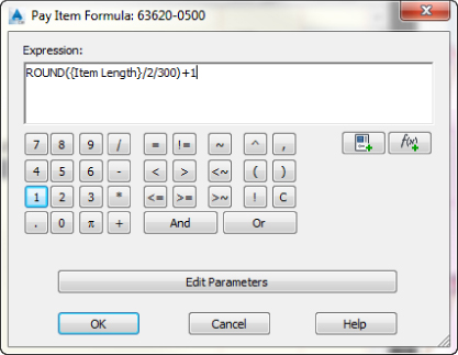
Figure 17.10 The completed pay item expression
Assume that you need a street light every 300 feet (or 100 m for metric) but only on one side of the street. To do this, you add up all the lengths of curb and then divide by 2 because you want only one half of the street to have lights. You then divide by 300 (or 100 for metric) because you are running lights in an interval. Finally, you round to the nearest integer and add 1 to make the number conservative.
- Enter the formula using the following steps:

- Click the Property button and select Item Length from the drop-down list.
- Use the buttons in the dialog or your keyboard to divide this value by 2 to get half of the curb length.
- Use the buttons in the dialog or your keyboard to divide this value by 300 (or 100), which is the spacing of the light standards.

- To round this value, move your cursor to the beginning of the expression, click the Function button, and select ROUND.
Note that there are also ROUNDUP and ROUNDDOWN expressions available if these are better suited for your calculations.
- Move your cursor to the end of the expression and add the closing parenthesis for the ROUND command.
- Use the buttons in the dialog or your keyboard to add 1 to the calculation to be conservative.
The formula should now match the one shown previously in Figure 17.10.
- Click OK.
Note that the pay item list now shows a small calculator icon on that row to indicate a formula is in use.
Now that you've modified the way the light poles will be quantified from your model, you can assign the pay items for light poles and road striping to your corridor object. This is done by modifying the code set, as you'll see in the next steps.
- In the Toolspace Settings tab, expand General Multipurpose Styles Code Set Styles, right-click All Codes, and select Edit to display the Code Set Style – All Codes dialog.
- On the Codes tab, expand the Point branch and find the row for Crown, as shown in Figure 17.11.
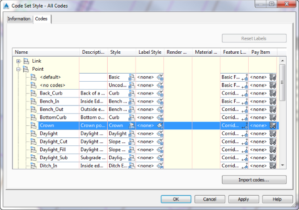
Figure 17.11 Select the Crown row in the Point branch in the Code Set Style – All Codes dialog.
As always, you may need to widen some of the columns to view the necessary text.
- Click the truck icon in the Pay Item column, shown in Figure 17.11, to open the Pay Item List dialog.
- Expand the Favorites branch, and select Pavement Markings, Type C, Broken.
- Click OK to return to the Code Set Style – All Codes dialog.
You should see the pay item number of 63401-0600 in the Pay Item column of your dialog.
- Again in the Point branch, find the row for Back_Curb, and repeat steps 11 through 13 to assign 63620-0500 to the Back_Curb code.
Remember, this is your light-standard pay item with the formula from the previous steps. Your Code Set Style – All Codes dialog should look like Figure 17.12, which lists a pay item for both of these point codes.
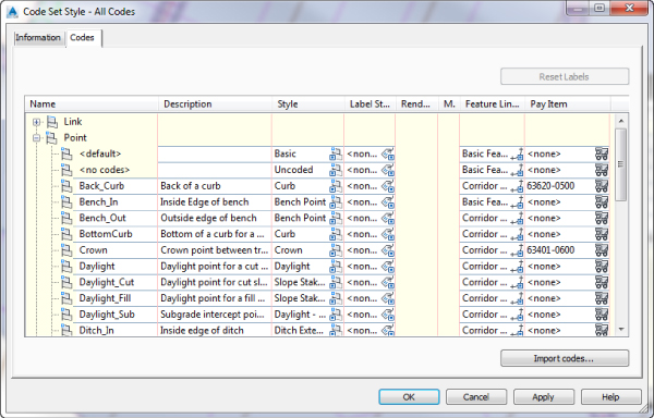
Figure 17.12 Completed code set editing for pay items
- Click OK to accept the settings in this dialog.
- Switch to Prospector and expand the Corridor branch.
- Right-click North River Crossing and select Properties to open the Corridor Properties dialog.
- On the Codes tab, expand the Point branch.
Notice that the Back_Curb and Crown codes reflect pay items in the far-right column.
- Click Cancel to exit the dialog.
When this exercise is complete, you can close the drawing. A saved copy of this drawing is available from the book's web page with the filename 1704_QTOCorridors_FINISHED.dwg or 1704_QTOCorridors_METRIC_FINISHED.dwg.
Corridors can be used to measure a large number of items. You've always been able to manage pure quantities of material, but now you can add to that the ability to measure linear and incremental items as well. Although we didn't explore every option, you can also use link codes to assign pay items to your corridor models. Point codes measure the length of the associated feature line. Link codes measure cumulative area between assemblies.
Now that you've looked at AutoCAD objects and corridors, it's time to examine the pipe network objects in Civil 3D as they relate to pay items.
Pipes and Structures as Pay Items
One of the easiest items to quantify in Civil 3D is the pipe network. There are numerous reports that will generate pipe and structure quantities. This part of the model has always been fairly easy to account for; however, with the ability to include it in the overall QTO reports, it's important to understand how parts get pay items assigned. There are two methods: via the parts lists and via the part properties. These methods can also be applied to pressure network pipes, fittings, and appurtenances.
Assigning Pay Items in the Parts List
Ideally, you'll build your model using standard Civil 3D parts lists that you've set up as part of your template. These parts lists contain information about pipe sizes, structure thicknesses, and so on. They can also contain pay item assignments. This means that the pay item property will be assigned as each part is created in the model, skipping the assignment step later.
In this exercise, you'll see how easy it is to modify parts lists to include pay items:
- Open the
1705_QTOPipeNetworks.dwgor1705_QTOPipeNetworks_METRIC.dwgfile. - On the Settings tab of Toolspace, expand the Pipe Network Parts Lists branch.
- Highlight and right-click Sanitary Sewer and select Edit to display the Network Parts List – Sanitary Sewer dialog.
- On the Pipes tab, expand the Sanitary Sewer PVC Pipe (PVC Pipe SI for metric) part family.

Notice that the far-right column is the Pay Item assignment column.
- Click the truck icon in the 8-inch PVC (or 200 mm PVC Pipe) row to display the Pay Item List dialog.
- Turn off categorization and enter PVC in the text box, as shown in Figure 17.13, and press ↲ to filter the dialog.

Figure 17.13 Filtering and selecting the 8-inch PVC conduit as a pay item
- Select the CONDUIT, 8-INCH, PVC item (CONDUIT, 200 MM PVC) as shown and click OK to assign this pay item to the applicable pipe part.
- Repeat steps 4 through 7 to assign pay items to 10- and 12-inch (250 mm and 300 mm) PVC conduits.
Your dialog should look like Figure 17.14.
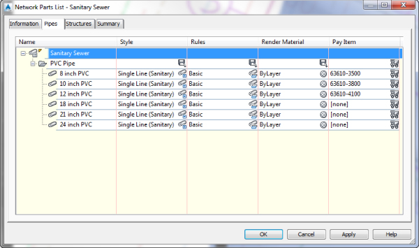
Figure 17.14 Completed pipe parts pay item assignments
- On the Structures tab of the Networks Parts List dialog, expand the Sanitary Sewer Concentric Cylindrical Structure branch (or Concentric Cylindrical Structure SI if metric).
- Click the truck icon on the Concentric Structure row to display the Pay Item List dialog.
- In the Pay Item List dialog under Favorites, select MANHOLE, SANITARY SEWER, and click OK.
The Network Parts List should now look similar to Figure 17.15.
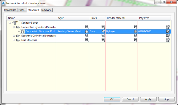
Figure 17.15 Completed structure parts pay item assignments
- Click OK to accept the settings in the Network Parts List.
When this exercise is complete, you can save the drawing and keep it open to continue on to the next exercise. Or you can use the saved copy of this drawing available from the book's web page (1705_QTOPipeNetworks_FINISHED.dwg or 1705_QTOPipeNetworks_METRIC_FINISHED.dwg).
Pay Items as Part Properties
If you have existing Civil 3D pipe networks that were built before your parts list had pay items assigned or if you change out a part during your design, you need a way to review and modify the pay items associated with your network. Unfortunately, doing so isn't as simple as just telling Civil 3D to reprocess some data, but it's not too complicated either. You simply remove the pay item associations and then add new ones.
In this exercise, you'll add pay item assignments to a number of parts already in place in the drawing:
- Continue working in your file, or open the
1705_PipeNetworks_FINISHED.dwgor1705_QTOPipeNetworks_METRIC_FINISHED.dwgfile. - If the QTO Manager is not already open, from the Analyze tab QTO panel choose QTO Manager to open it.
- Slide the QTO Manager to one side, and then select one of the manholes in the Sanitary Network (they have an S symbol on them).
- Right-click and choose Select Similar. Fourteen manholes should highlight, as shown in Figure 17.16.
Figure 17.16 Use Select Similar to find all sanitary manhole structures.
- In the QTO Manager, expand Favorites and select MANHOLE, SANITARY SEWER.
- Click the Assign The Selected Pay Items To Object(s) In The Drawing button.
- At the command line, press ↲ to complete the assignment.
You can pause your cursor over one of the manholes, and the tooltip will reflect a pay item now, in addition to the typical information found on a manhole.
When this exercise is complete, you may save the drawing and keep it open to continue on to the next exercise. Or you may use the saved copy of this drawing available from the book's web page (1706_QTOPipeNetworks_FINISHED.dwg or 1706_QTOPipeNetworks_METRIC_FINISHED.dwg).
Assigning pay items to existing structures and pipes is similar to adding data to standard AutoCAD objects. As mentioned before, the pay item assignments sometimes get confused in the process of changing parts and pipe properties, and they should be manually updated. To do so, you'll need to remove pay item data and then add it back in, as demonstrated in this exercise:
- Continue working with your file or open the
1706_QTOPipeNetworks_FINISHED.dwgor1706_QTOPipeNetworks_METRIC_FINISHED.dwgfile. - Pan to the west end of ROAD A where the sanitary sewer network terminates.
- Pause your cursor over the pipe connected to the structure at the termination of the sewer network.
The tooltip will appear indicating the pipe information but no pay item, as shown in Figure 17.17.
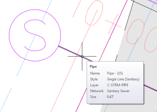
Figure 17.17 Tooltip for a pipe without an assigned pay item
- Select the pipe, and from the contextual tab Modify panel, select Swap Part.
This will display the Swap Part Size dialog.
- Select 12 Inch PVC (or 300 mm PVC Pipe) from the list of sizes (the original size of pipe—you are not changing the diameter) and then click OK.
- Pause near the newly sized pipe and notice that the tooltip now shows the pay item, as shown in Figure 17.18.
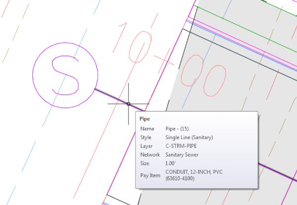
Figure 17.18 Tooltip after the pipe part has been swapped to a part with an assigned pay item
When this exercise is complete, you may close the drawing. A saved copy of this drawing is available from the book's web page with the filename 1707_QTOPipeNetworks_FINISHED.dwg or 1707_QTOPipeNetworks_METRIC_FINISHED.dwg.
You might wonder why Civil 3D allows you to have multiple pay items on a single object. For example, linear feet of striping and tree counts can both be derived from street lengths; bedding and pipe material can both be calculated from pipe objects. You can also add related tasks to an item. For instance, a tree is usually a pay item by itself, but the labor to install the tree may be treated as a separate pay item.
You've now built up a list of pay items, tagged your drawing a number of ways, updated and modified pay item data, and looked at formulas in pay items. In the next section, you'll make a final check of your assignments before running reports.
Highlighting Pay Items
Before you run any reports, it's a good idea to make a cursory pass through your drawing and look at what items have had pay items assigned and what items have not. This review will allow you to ideally catch missing items (such as hydrants added after the pay item assignment was done) as well as see any items that perhaps were blocked in with unnecessary pay items already assigned. In this exercise, you'll look at tools for highlighting objects with and without pay item assignments:
- Open the
1708_QTOHighlighting.dwgor1708_QTOHighlighting_METRIC.dwgfile. - From the Analyze tab QTO panel, choose QTO Manager to display the QTO Manager.

- In the QTO Manager, select Highlight Objects With Pay Items, as shown in Figure 17.19.
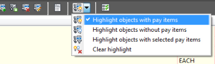
Figure 17.19 Turning on highlighting for objects with pay items assigned
Notice that from this same drop-down menu you can also choose Highlight Objects Without Pay Items, Highlight Objects With Selected Pay Items, or Clear Highlight.
- Pan around the drawing and zoom in on the trees at the intersection of ROAD A and ROAD B.

- In the QTO Manager, select Highlight Objects Without Pay Items.
Notice that the trees turn from green to muted gray. This means they have a pay item assigned.
- In the QTO Manager, switch back to Highlight Objects With Pay Items.

Next, you will change the pay item assignment for the trees at the intersection of ROAD A and ROAD B since the planner has decided to use a different tree type.
- In the QTO Manager, click the Remove Pay Item(s) From Specified Objects button.
- At the
Select object(s):prompt, select five of the trees near the intersection and press ↲ to end the command.Notice that the trees go from green to a muted gray, indicating that they no longer have a pay item associated since the highlighting is enabled.
- In the QTO Manager, enter Maple in the text box to filter.
- Turn the categorization option off to more easily see the filtered results.
- Select item 62601-0100.

- Click the Assign The Selected Pay Items To Objects In The Drawing button.
- At the
Select pay item(s) from master pay item list or [Enter]:prompt, press ↲. - At the
Select object(s):prompt, select the same five trees that you just unassigned pay items from and press ↲ to end the command.Notice that the trees go from a muted gray to green, indicating that they once again have pay items associated with them since the highlighting is enabled.
Unassigning and then reassigning a pay item may seem cumbersome. Instead, you may find it simpler to edit the pay item.

- In the QTO Manager, click the Edit Pay Items On Specified Object button.
- At the
Select object(s):prompt, select the remaining tree near the intersection to display the Edit Pay Items dialog. - Select the FAGUS GRANDIFLORIA row and then click the red X in the upper right to remove this pay item from the tree, as shown in Figure 17.20.
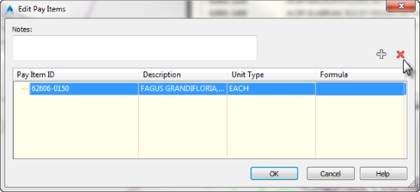
Figure 17.20 Editing pay item assignments: deleting the tree pay item
- Click the plus sign in the upper right to display the Pay Item List dialog in order to add a new pay item to the tree.
- Enter Maple in the text box to filter.
- Select item 62601-0100 and click OK.
- Click OK to accept the new pay item designation shown in the Edit Pay Items dialog.
- In the QTO Manager, select Highlight Objects Without Pay Items from the drop-down menu shown previously in Figure 17.19.
This switches the highlighting from objects that do have pay items to objects that do not have pay items.

- In the QTO Manager, select Clear Highlight to return the drawing view to normal.
When this exercise is complete, you may close the drawing. A saved copy of this drawing is available from the book's web page with the filename 1708_QTOHighlighting_FINISHED.dwg or 1708_QTOHighlighting_METRIC_FINISHED.dwg.
While highlighting objects with QTO Manager, you can add, remove, or edit pay items using the tools at the top of the QTO Manager. You can leave the objects highlighted while performing any other AutoCAD command. This makes it easier to correct any mistakes made during the assignment phase of the process. Finally, always be sure to clear highlighting before exiting the drawing or your peers might wind up awfully confused when they open the file!
Inventorying Your Pay Items
At the end of the process, you need to generate some sort of report that shows the pay items in the model, the quantities of each item, and the units of measurement. This data can be used as part of the plan set in some cases, but it's often requested in other formats to make further analysis possible. In this exercise, you'll look at the Quantity Takeoff tool that works in conjunction with the QTO Manager to create reports:
- Open the
1709_QTOReporting.dwgor1709_QTOReporting_METRIC.dwgfile. - From the Analyze tab QTO panel, choose Takeoff to display the Compute Quantity Takeoff dialog, shown in Figure 17.21.
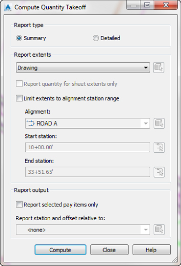
Figure 17.21 The Compute Quantity Takeoff dialog with default settings
- Click Compute to open the Quantity Takeoff Report dialog, as shown in Figure 17.22.
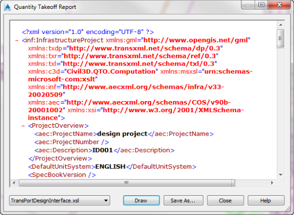
Figure 17.22 Quantity Takeoff Report in the default XSL format
The report is shown in the default Extensible Stylesheet Language (XSL) format.
- From the drop-down menu on the lower left of the dialog, select Summary (TXT).xsl to change the format to something more understandable, as shown in Figure 17.23.

Figure 17.23 Quantity Takeoff Report in the Summary TXT format
At this point, you can export this data as a text file, but for the purpose of this exercise, you'll simply insert it into the drawing.
- Click the Draw button at the bottom of the dialog.
- At the
Select report table origin:prompt, click near some clear space, and you'll be returned to the Quantity Takeoff Report dialog. - Click Close to dismiss this dialog and then click Close again to dismiss the Compute Quantity Takeoff dialog.
- The program zooms into where you clicked in step 6, and you should see something like Figure 17.24.
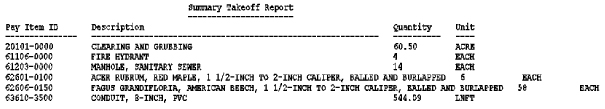
Figure 17.24 Summary takeoff data inserted into the drawing
When this exercise is complete, you may close the drawing. A saved copy of this drawing is available from the book's web page with the filename 1709_QTOReporting_FINISHED.dwg or 1709_QTOReporting_METRIC_FINISHED.dwg.
That's it! The hard work in preparing QTO data is in assigning the pay items. The reports can be saved to HTML, TXT, or XLS format for use in almost any analysis program.
The Bottom Line
- Open and add to a list of pay items. The pay item list is the cornerstone of quantity takeoffs. You should download and review your pay item list and compare it against the current reviewing agency list regularly to avoid any missed items.
- Master It Using the template of your choice, open the
Getting Started.csv(orGetting Started_Metric.csv) pay item file that you have been working with in the previous exercises and add the 12-, 18-, and 24-Inch Pipe Culvert (or 300 mm, 450 mm, and 600 mm Pipe Culvert) pay items to your Favorites list in the QTO Manager.
- Master It Using the template of your choice, open the
- Assign pay items to AutoCAD objects and pipe networks. The majority of the work in preparing quantity takeoffs is in assigning pay items accurately. By using the linework, blocks, and Civil 3D objects in your drawing as part of the process, you reduce the effort involved in generating accurate quantities.
- Master It Open the
MasteringQTO.dwgorMasteringQTO_Metric.dwgfile and assign the CLEARING AND GRUBBING pay item to the polyline that was originally extracted from the border of the corridor. Change the hatch to have a transparency of 80.
- Master It Open the
- Use QTO tools to review what items have been tagged for analysis. By using the built-in highlighting tools to verify pay item assignments, you can avoid costly errors when running your QTO reports.
- Master It Verify that the area in the previous exercise has been assigned a pay item.
- Generate QTO output to a variety of formats for review or analysis. The quantity takeoff reports give you a quick understanding of what items have been tagged in the drawing, and they can generate text in the drawing or external reports for uses in other applications.
- Master It Display the length of Type C Broken markings in a Quantity Takeoff Report with the Summary (TXT) report style using the
MasteringQTOReporting.dwgorMasteringQTOReporting_Metric.dwgfile.
- Master It Display the length of Type C Broken markings in a Quantity Takeoff Report with the Summary (TXT) report style using the