Meet the beagles
Abstract
This chapter introduces the BeagleBoard and BeagleBone family of ARM-based computer boards. The Beagles are open hardware devices. Full specifications for all components and schematics are freely available for open hardware items. Additionally, designs may be freely cloned, modified, or extended without legal concerns.
Introduction
Imagine using a device that you find indispensable, something that you might use every day. Now, imagine that you have come up with an improvement. Most of the devices that you use are protected by patents and copyrights. Furthermore, in the United States, it is potentially illegal to figure out how something works, a process known as reverse engineering. Many companies insert anti-reverse engineering clauses in their end-user license agreements (EULA) in order to discourage reverse engineering of their products. Concerned about legal issues, you forget about your innovation and life goes on with a device that is okay, but could be better.
There are some in the world, this author included, that find this scenario unacceptable. Imagine a better world in which you can find out everything you wish to know about any device, a place where designs are fully documented and can be freely used to improve or modify a device, and a land in which a design could even be completely embedded inside a new design without fear of lawsuits. You have just entered the world of open hardware (sometimes known as open-source hardware).
Open hardware allows society as a whole to advance at a quicker pace. There are open prototyping platforms such as the Arduino (http://arduino.cc), open 3-D printers (i.e., http://reprap.org), and even open satellites. Making a hardware design open increases the number of people who might come up with improvements. While it may seem counterintuitive, companies designing and manufacturing open hardware can be profitable. One need only look at the Arduino project with its scores of projects and strong community support to see what a successful open hardware project can look like. Open hardware designs can showcase the capabilities of various hardware components.
Texas Instruments Devices
In part to showcase some of their chips and to encourage their use, Texas Instruments (TI) allows some employees to develop and promote open hardware computer boards featuring TI products (see http://beagleboard.org/about for more details). These boards are developed by a US-based nonprofit corporation known as the BeagleBoard.org Foundation. At the time of this writing, two TI employees are devoting considerable effort to the BeagleBoard.org Foundation. Jason Kridner serves as community manager and Gerald Coley is responsible for hardware design.
BeagleBoard-xM
The very first board developed by BeagleBoard.org is known as the BeagleBoard. The BeagleBoard was released in July 2008 and is still available today. Based on the 720 MHz TI OMAP3530 Cortex-A8 processor, this board features 256 MB RAM, 256 MB flash memory, HDMI video, S-Video, USB On-The-Go port, USB host port, SD card slot, RS-232 port, and stereo audio. The list price for this 75 mm by 75 mm board is $125.
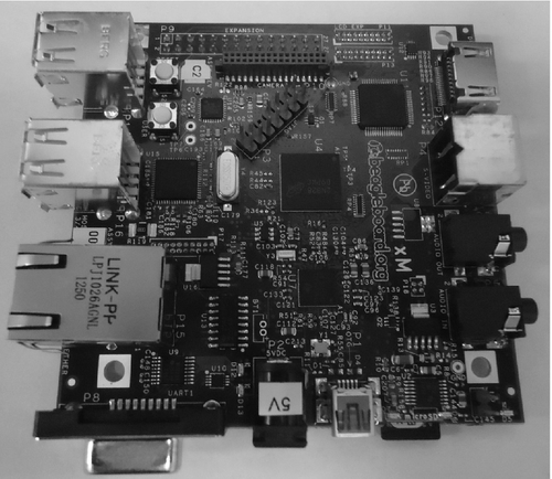
An updated board known as the BeagleBoard-xM was released in September 2010. The BeagleBoard-xM is billed as a $149 desktop replacement (Figure 2.1). I will summarize some of its features here using the BeagleBoard-xM System Reference Manual, which is available at http://circuitco.com/support/index.php?title=BeagleBoard-xM#Rev_C2.
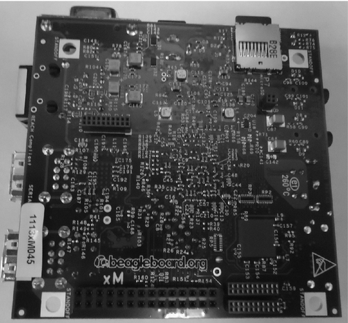
Texas Instruments bills the 1 GHz DM3730 processor found in the BeagleBoard-xM as a digital media processor (see http://www.ti.com/product/dm3730 for full details). This processor features a NEON SIMD coprocessor, which can significantly speed up multimedia applications and mathematical calculations (http://www.arm.com/products/processors/technologies/neon.php). This processor utilizes a package on package (POP) design. The 512 MB RAM chip is installed on top of this chip. This processor is more than sufficient to run a full-featured Linux and standard penetration testing tools. The BeagleBoard-xM is pictured in Figures 2.2 and 2.3.
A Texas Instruments TPS65950 chip is used for power management and audio on the BeagleBoard-xM (details at http://www.ti.com/product/tps65950). While this might seem like a strange combination to put on a chip, the chip is designed to be used with TI's set of processors in embedded applications where low chip count is an important design criterion. The TPS65950 allows the BeagleBoard-xM to be powered by the USB OTG (On-The-Go) connection when connected to a PC. This is not recommended when running lots of peripherals and/or a LCD touchscreen as the PC USB port may not be able to supply sufficient power. A USB Y-cable, powered USB hub, or external 5 V (2 A) power supply may be required when using USB peripherals with high-power requirements.
The BeagleBoard-xM has four USB 2.0 host ports. Each port is capable of supplying up to 500 mA provided the board is powered via the DC input power connector and not the USB OTG port. The System Reference Manual recommends a 3 A power supply if all the ports are to be used. In my experience, a 2 A power supply is more than sufficient even when running a 1 W Alfa wireless adapter. All three USB 2.0 speeds (low, full, and high) are supported.
The BeagleBoard-xM provides three options for video output: S-Video, DVI-D via HDMI connector, and LCD touchscreen. The S-Video connection can be used to connect the BeagleBoard-xM to a NTSC (default) or PAL television. The board may be configured to send different videos to the S-Video and DVI-D connections. A full-size HDMI connector is used to connect the BeagleBoard-xM to a digital monitor or television. The DVI-D protocol is essentially the same as HDMI with the exception of not supporting sending audio over the HDMI cable. Enhanced Display ID (EDID) or Display Data Channel (DDC2B) is used to identify an attached monitor and configure video settings appropriately. Plugging in your monitor cable before you power up the BeagleBoard-xM is recommended to avoid surges, which could damage the board and for proper monitor identification. A pair of 0.05 in. 2 × 10 headers allow an LCD screen, such as the 7 in. touchscreen (http://elinux.org/Beagleboard:BeagleBone_LCD7) for the lunchbox computer shown in the last chapter, to be directly connected to the BeagleBoard-xM.
The BeagleBoard-xM has one microSD card slot. The board supports high-capacity microSD cards. This is primarily used to house the operating system, but you can and should buy a larger card if you want to store data without the need to attach a USB mass storage device (which would increase your power usage among other things). When buying microSD cards, it is well worth the extra money to get a class 10 card. The use of class 4 or class 6 cards will have a noticeable impact on performance. Communication with the microSD card is 4 bits with a 20 MHz clock.
Two buttons and six LEDs are used to facilitate user interaction on the BeagleBoard-xM. One of the buttons is used for power on reset and the other is user configurable. The five green LEDs are used for indicating that the board is powered, that the USB hub circuitry is powered, and that the remaining three LEDs are programmable via I2C (1) or GPIO (2). There is also a red over- or under-voltage LED that illuminates if anything other than 5 V is applied to the DC input. While the processor and most of the circuits on the board are 3.3 V, 5 volts is required to operate the USB circuitry.
The BeagleBoard-xM features an integrated Fast Ethernet (100 Mbps) port. Ethernet support is provided by the SMSC LAN9514 chip, which also includes a USB hub used by the four USB host ports. It is important to realize that this chip will serve up a different MAC address each time your machine boots, likely resulting in a different address assignment each time if you are using DHCP.
There are a number of additional connectors on the BeagleBoard-xM that you might not be likely to use for hacking and penetration testing. A JTAG connector is provided for testing and debugging of the board. A DB9 RS-232 serial port is available for connecting to older devices or as a serial console. A camera module may be connected to a dedicated connector on the board. Several expansion headers allow access to GPIO lines and other functions.
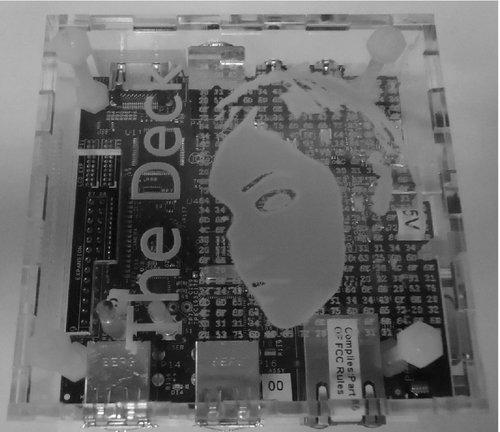
It is highly recommended that the BeagleBoard-xM be protected by an enclosure such as the one shown in Figure 2.4. Several case options are available from simple acrylic cases from Special Computing (http://specialcomp.com) to the metal doghouse case from eSawdust (http://www.esawdust.com/product/encl-dh-xm/). At a minimum, some acrylic sheet (or other nonconductor) and some standoffs will provide protection from shorting should the board be placed on a conducting service while energized.
BeagleBone
The BeagleBone was released on Halloween (31 October) 2011 (http://beagleboard.org/Products/BeagleBone). Many people became interested in building custom electronic devices based on microcontrollers after the release of the Arduino Duemilanove in 2009 (http://arduino.cc). For those unfamiliar with the Arduino, it is another open-source hardware project. A community quickly formed around this board, which sold for less than US$35. Arduino brought microcontrollers within reach of nontechnical people by providing them with a board that accepted plug-in expansion boards, known as shields, and an easy to use programming environment with an extensive set of libraries. While you can do a lot with an Arduino featuring a 16 MHz 8-bit AVR microcontroller, some projects require more computing power. This is where the BeagleBone comes in.
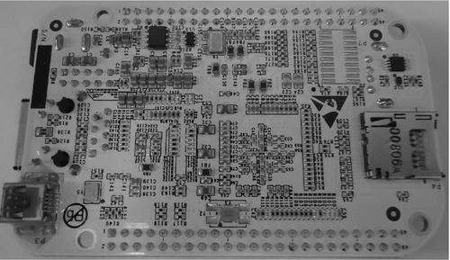
The BeagleBone can be thought of as an extremely high-powered Arduino-type board. The Texas Instruments Cortex-A8 32-bit processor running at 720 MHz opens many doors closed to the 16 MHz 8-bit processor found on the Arduino. In addition to having added power for general computing and mathematics, the BeagleBone can run a proper operating system (the Arduino has just enough power to run the one program loaded into it). Like the Arduino, it is designed to be used with expansion boards. The layout of expansion headers for each board is not the same. BeagleBone expansion boards are called capes, partially because they often feature a cutout to provide clearance around the Ethernet port, which makes them cape-shaped. The BeagleBone appears in Figures 2.5 and 2.6.
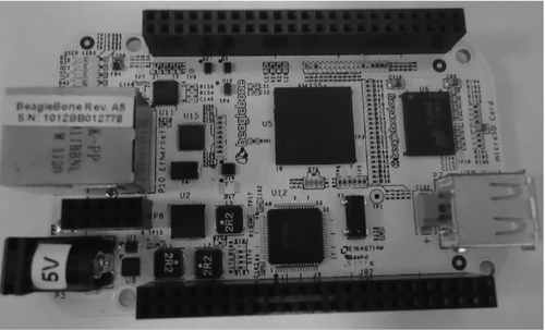
The following information comes from the BeagleBone System Reference Manual, which is available at http://circuitco.com/support/index.php?title=BeagleBone#Rev_A6A. Like the BeagleBoard-xM, the BeagleBone features a Cortex-A8 processor, albeit in a different package and at a slightly lower speed. The big upside to this is that the same software and operating systems that run on the BeagleBoard-xM also run on the BeagleBone. Given that the BeagleBoard has been out since 2008, there is a large selection of operating systems and software available.
The BeagleBone has 256 MB of DDR2 RAM, half of what is found in the BeagleBoard-xM. This can be an issue when running some larger applications (such as the Metasploit framework). It does compare very favorably to the 2 KB of RAM found in the Arduino, however. System information such as board name, revision, and serial number is stored in a 32 KB (4 KB for early editions) EEPROM on the BeagleBone. Most of the EEPROM space is unused leaving it available to applications and/or the operating system. Incidentally, the Arduino also has 32 KB of nonvolatile storage in the form of flash memory, which is used to store a bootloader and a single program.
The BeagleBone may be powered by a 5 V DC power adapter or by USB. A Texas Instruments TPS65127B power management chip is utilized on the BeagleBone. It should be noted that when powered by the USB client port, the CPU speed is limited to 500 MHz in order to assure that sufficient power is available to run the board and any USB peripherals. A DC power supply delivering 5 ± 0.1 V at 1 A is recommended when using the DC power input.
Another plus for the BeagleBone over the Arduino is support for USB. A USB hub on BeagleBone allows multiple USB devices to use a single cable. When connected to a PC, the BeagleBone presents itself as a serial debug port, a JTAG port, and a USB0 port, which is directly connected to the processor. A single USB host port is provided that can supply up to 500 mA at 5 V when the BeagleBone is powered by a DC power supply. When the BeagleBone is powered by USB, only low-power devices, such as keyboards and mice, should be plugged into the USB host port.
Like the BeagleBoard-xM, the BeagleBone features a microSD socket. The microSD is used to store the operating system and other files as the BeagleBone has no built-in storage. Access is 4 bits (standard for SD cards). The BeagleBone supports standard 3.3 V microSD cards including high-capacity cards. While the Arduino does not have built-in support for SD storage, a number of shields are available to provide this support if you don't mind giving up several GPIO lines.
Another advantage of the BeagleBone over the Arduino is built-in fast Ethernet. Unlike the BeagleBoard-xM, Ethernet is supported with a dedicated networking chip, not one that also does USB. The chip used is a SMSC LAN8710A. Because of this difference, the BeagleBone reports a consistent MAC address and will likely be assigned the same address on each boot when connected to networks utilizing DHCP.
Expansion capes are attached to the BeagleBone via two 46-pin headers. Up to four stackable capes may be used at once provided they don't interfere with each other. It is hard to imagine a project that the BeagleBone can't handle. There are up to 66 GPIO pins available (compared to only 14 on the Arduino). It is important to note that GPIO pins on the BeagleBone are 3.3 V, not 5 V. A full LCD touchscreen with backlight is supported. An additional SD/MMC card can be connected to the BeagleBone via processor pins, which are exposed to the expansion headers.
There are two common standards for connecting peripherals to embedded electronics: SPI and I2C. Both of these standards are supported by the BeagleBone. There are two SPI and two I2C connections. Each of these connections supports multiple devices. The second I2C interface must be used with care as it is used by the BeagleBone to identify and configure capes (more detail on this is forthcoming). The Arduino supports one SPI and one I2C connection.
Four serial ports are available via the expansion headers. One of these serial ports will be used to connect the IEEE 802.15.4 radios used in our remote hacking drones. The BeagleBone also supports two CAN buses. The fairly low-speed, but reliable CAN protocol is commonly used in automobiles but may be found in other contexts.
Timers, analogue to digital converters (ADCs), and pulse width modulation (PWM) round out the BeagleBone's expansion capabilities. Four time outputs are exported to the expansion headers. These timers can be very useful for periodic tasks or for restarting components on a cape. Seven analogue to digital conversion (ADC) channels capable of making up to 100,000 measurements per second are provided. The ADC channels allow an array of traditional analogue sensors to be used. The ADCs are 1.8 V and must be used with care as they are connected directly to the processor. PWM allows you to adjust the duty cycle of an electrical signal. It is commonly used to run servomotors and to adjust the brightness of LEDs.
While there are no rules on how capes should be built, there are recommended standards to maximize compatibility. In order for a cape to be sold by the standard Beagle vendors, it will likely need to at least have an EEPROM that is used to identify it to the BeagleBone. The second I2C bus is used for communicating with this EEPROM. Two jumpers or dip switches are required to set the I2C address for the EEPROM in order to allow up to four capes to be stacked together without having the EEPROMs interfere with each other.
As with the BeagleBoard-xM, an enclosure to protect the BeagleBone is strongly recommended. There are a number of vendors such as Special Computing (http://specialcomp.com) and Adafruit Industries (http://adafruit.com) selling cases. The preferred case may vary from one situation to the next depending on capes to be used. At a minimum, some acrylic or other nonconducting sheets should be attached by standoffs to avoid shorting out the board if it is not embedded inside something. If you make your own enclosure, use the smallest standoffs possible as some of the small surface-mount electronic components are very close to the mounting holes and could be easily damaged.
It should be pretty clear to you by now why the BeagleBone is so popular among people wanting to build some hard-core electronics. As you will learn in this book, the BeagleBone is also a capable and compact computer system. This is true to an even greater extent with the new upgraded BeagleBone Black edition to be discussed next.
BeagleBone Black
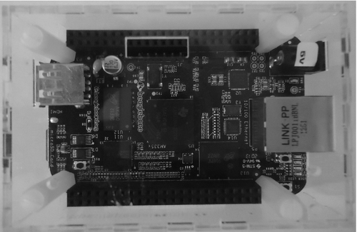
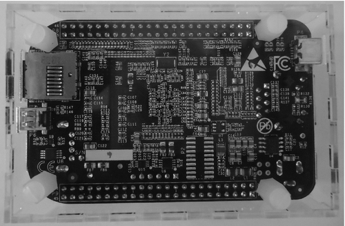
While the BeagleBone was quite revolutionary at the time of its release, advancements in technology led to the release of an ever more powerful version of the board known as the BeagleBone Black edition (BBB for short) at half the price (US$45 versus US$89). The BeagleBone Black was released on April 23, 2013, less than 18 months after the release of the original version. The primary reasons for the cost reduction are a reduced chip count and larger production batches. The BeagleBone Black appears in Figures 2.7 and 2.8.
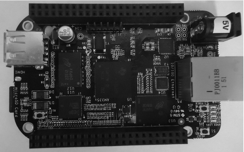
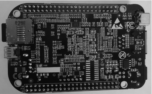
In addition to the low price, there are a number of improvements in the new BeagleBone. The processor speed has been increased from 720 MHz to 1 GHz. RAM has been doubled from 256 to 512 MB. The BeagleBone Black uses DDR3 memory, which is now cheaper than the DDR2 RAM found in the original BeagleBone. Information on the BeagleBone Black presented here is from the BeagleBone Black System Reference Manual, which is available at https://github.com/CircuitCo/BeagleBone-Black/blob/master/BBB_SRM.pdf.
The BeagleBone Black has 2 GB of eMMC nonvolatile storage (as of this writing, there is discussion of expanding this to 4 GB in later revisions). Ångström Linux comes installed on the eMMC (it was recently announced that Debian Linux will soon ship with new boards). Access to the eMMC is 8 bits as opposed to 4 bits for the microSD card reader. The fact that the eMMC configuration is known (as opposed to something that must be discovered when a microSD card is inserted) allows eMMC access to be optimized. For these reasons, significant performance improvements may be realized when using eMMC instead of a microSD card for the root filesystem. Unfortunately, in our case, The Deck with its 6 GB plus root filesystem is much too large to be stored on the eMMC.
One of the most noticeable additions to the BeagleBone Black is HDMI video via a microHDMI connector. HDMI support is provided by a NXP TDA19988 HDMI framer. The BeagleBone Black supports resolutions up to 1920 × 1080. By default, the BeagleBone Black will use the highest compatible resolution reported by the EDID process. For this reason, it is important to connect and power up the monitor before booting the BeagleBone Black. Unlike the BeagleBoard-xM, the full HDMI specification, including audio, is supported. Only resolutions specified in the Consumer Electronics Association (CEA) standards support audio. Because every HD television supports these resolutions, you should have no problem finding a display for your BeagleBone Black.
While not as easily noticeable as a new HDMI connection, the BeagleBone Black is also more energy-efficient than the original. Elimination of several chips has resulted in significant reduction in required current (roughly 30%). As a result, battery-powered hacking drones based on the BeagleBone Black can run longer than drones based on the original BeagleBone.
The BeagleBoard.org team tried to make the new BeagleBone as compatible with the original as possible. When purchasing capes, be sure to check that they are compatible with the BeagleBone Black. Compatibility can be checked at http://elinux.org/Beagleboard:BeagleBone_Capes. The addition of eMMC and HDMI resulted in several pins that were formerly available on the expansion headers being used by the BeagleBone. Capes that use the same lines as eMMC or HDMI will only function properly with the conflicting service disabled. Given that The Deck is too large to fit on the eMMC and that HDMI output isn't needed for hacking drones, this should be a nonissue for our purposes. There are other differences between the two BeagleBone versions, but they are unlikely to pose problems in our penetration testing efforts. Consult the System Reference Manual to learn more about these differences.
As always, the BeagleBone Black should be protected from shorting by either using an enclosure or embedding it inside a nonconducting material. Adafruit (http://www.adafruit.com/category/75) sells both a small acrylic case and a larger case intended to house a BeagleBone with one or more capes. Most of the other BeagleBone Black vendors such as Special Computing (https://specialcomp.com/beaglebone/) seem to offer simple acrylic cases for around US$10. The Special Computing case is shown in Figures 2.9 and 2.10. Cases for the original BeagleBone may be used after a slot for the microHDMI connector has been created with a rotary tool or similar. Should you decide to make your own case, be careful not to use overly large standoffs as you might damage components close to the mounting holes.
Summary
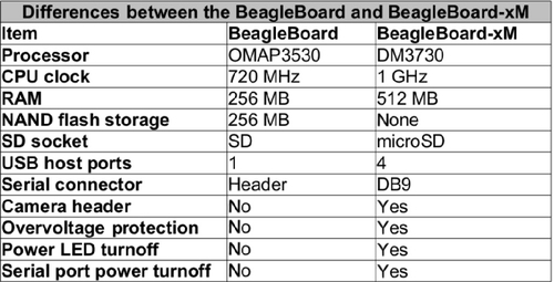
The differences between the BeagleBone Black, original BeagleBone, and BeagleBoard-xM are presented in Table 2.1. This information is taken from a chart at http://beagleboard.org/Products.
Table 2.1
Comparison of BeagleBone Black, original BeagleBone, and BeagleBoard-xM
| BeagleBone Black | BeagleBone | BeagleBoard-xM | |
| Processor | AM3358 ARM Cortex-A8 | AM3358 ARM Cortex-A8 | DM3730 ARM Cortex-A8 |
| Max CPU speed | 1 GHz | 720 MHz | 1 GHz |
| Analogue pins | 7 | 7 | 0 |
| Digital pins (voltage) | 65 (3.3 V) | 65 (3.3 V) | 53 (1.8 V) |
| Memory | 512 MB DDR3 | 256 MB DDR2 | 512 MB LPDDR |
| USB | HS USB client/host | HS USB client/host | 4 HS USB hub, USB OTG |
| Video | MicroHDMI, capes | Capes | DVI-D, S-Video |
| Audio | Via HDMI | Capes | 3.5 mm connector |
| Supported interfaces | 4 × UART, 8 × PWM, LCD, GPMC, MMC1, 2 × SPI, 2 × I2C, A/D converter, 2xCAN bus, 4 timers | 4 × UART, 8 × PWM, LCD, GPMC, MMC1, 2 × SPI, 2 × I2C, A/D converter, 2xCAN bus, 4 timers, FTDI USB to serial, JTAG via USB | McBSP, DSS, I2C, UART, LCD, McSPI, PWM, JTAG, camera interface |
| List price | US$45 | US$89 | US$149 |
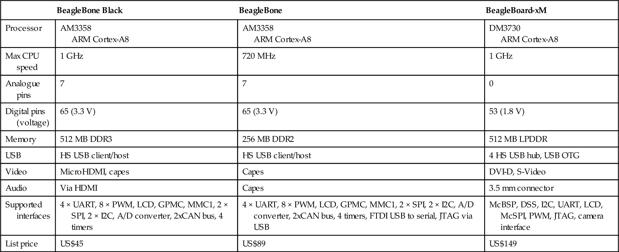
In this chapter, we learned about the open hardware small computer boards from BeagleBoard.org. The US$149 BeagleBoard-xM allows us to create compact and energy-efficient penetration testing desktop systems. The latest board, the BeagleBone Black, is available for only US$45 while providing nearly identical performance to the BeagleBoard-xM. The BeagleBone Black is equally adept as a penetration testing desktop or hacking drone. Now that you have been introduced to The Deck and the hardware it runs on, we will dive into the details of installing a base operating system in the next chapter.