Adding air support
Introduction
In the previous chapter we learned how to plant devices in and around your target's facilities. The techniques discussed work well when there is sufficient access to a location. In some cases the access to a target's office might be limited. In those cases, an alternate method of bringing drones to bear might be useful.
One of the ways to deliver hacking hardware is by air. Aerial delivery allows fences to be bypassed. It also permits your hardware to hang out on the roof undetected by your penetration test subject. In this chapter we will discuss building an aerial hacking drone. This is the kind of equipment that you won't need on every penetration test, but when you need something like this you tend to really need it.
Building the AirDeck
We will begin our journey into airborne hacking drones by establishing a set of desired parameters for an aerial platform. Once an airframe has been selected different configurations will be discussed. The device described here is known as the AirDeck, short for airborne hacking drone running The Deck. Basic soldering and assembly skills are all that are required to build the AirDeck.
Selecting a Platform
Before selecting a platform for our aerial drone, we must first establish the necessary aircraft characteristics. The chosen airframe should have a good payload. How much? Minimally the drone should be capable of carrying a BeagleBone Black, Xbee radio, and Alfa wireless adapter. In the ideal situation the aircraft can also lift a camera and GPS.
The chosen aircraft should be capable of flying in windy conditions. Many toy quadcopters can only be operated indoors thanks to their inability to be flown in even a light breeze. The amount of wind that you have to deal with can vary significantly from one location to the next.
The ideal aircraft is capable of Vertical Take Off and Landing (VTOL). This permits the drone to be parked on a roof or other surface out of sight of the target. While VTOL is a great thing to have, an airframe that can also be flown as an airplane is desirable as it saves energy.
The drone needs to have sufficient flight time to get it in and out. It would be convenient if battery power from the drone could also be tapped to operate the BeagleBone Black. Twenty minutes should be more than enough flight time. A drone that can only be flown for ten minutes or less is not terribly useful.
The chosen platform should have space for the BeagleBone Black, Xbee, and Alfa wireless adapter. If there is a way to fit a long range wireless antenna and large battery that is even better. The selected airframe must also be robust and affordable.
There are several suitable aircraft for our purposes. I elected to use the QuadShot from Transition Robotics (http://thequadshot.com). The QuadShot is a flying wing platform with four motors that allow it to be operated as an airplane or as a quadcopter. The QuadShot is shown in Figure 9.1.
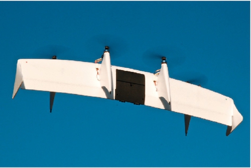
The QuadShot meets our criteria. It has VTOL capabilities. Thanks to the ability to be flown as an airplane, it can be flown in considerable wind. The manufacturer claims that it is capable of carrying a half pound of payload. When flown as an airplane, flight times of 15-20 min are possible. The QuadShot has a place to mount an Xbee module and camera.
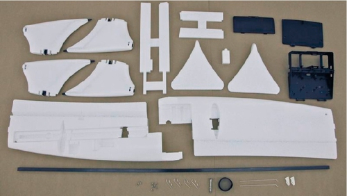
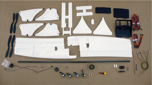
Several models of the QuadShot are available. The most basic model known as the Latte is just an airframe, no motors, radios, or controller boards. The QuadShot Latte is shown in Figure 9.2. If you lack a convenient source for motors and such, but still want to create your own controller, etc. the QuadShot Cappuccino has most of what you need minus a radio and controller board. The Quadshot Cappuccino is shown in Figure 9.3.
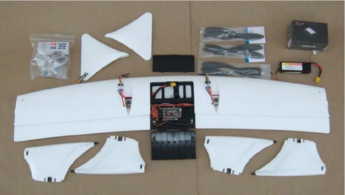
The QuadShot Mocha is a ready-to-fly aircraft. It includes a complete aircraft and radio controller. It is available as a kit or pre-assembled. If you are uncomfortable building an RC aircraft it might be worth the extra cost to buy the prebuilt kit. This is the kit I used to build the AirDeck presented in this chapter. The QuadShot Mocha is shown in Figure 9.4. Transition Robotics offers other, more advanced, versions of the QuadShot, but they are overkill for our purposes.
The Router-only Option
In the absolute simplest use case, the QuadShot can be equipped with a Xbee radio configured as a router and used to extend the reach of your penetration test. This router-only aircraft could also be used in cases where hacking drones are equipped with low-power transmitters in order to conserve batteries, but where the command console is too far away from the drones.
There are several nice things about this option. The QuadShot has a mounting location for an Xbee adapter installed on a serial interface board by Transition Robotics. This board with an Xbee adapter installed is shown in Figure 9.5. Because the Xbee is installed inside the QuadShot there would be no reason for anyone to suspect what you are really doing with your aircraft if it were to be discovered. Because there is no need to power a BeagleBone, battery life in this configuration can be quite good. The drone can also be flown out periodically to refresh the batteries.
There are some downsides to this configuration. The LEDs on the QuadShot are always on by default. This draws attention to the aircraft and also drains the battery needlessly. The lights help the pilot orient the QuadShot in flight. As a result, completely disabling the lights is not recommended. The controller board on the QuadShot is open source and could be reprogrammed to turn off the LEDs after some inactivity. Speaking of the controller board, it also leaches power needlessly while the QuadShot is not in the air. This too could be fixed by hacking the controller board software to sleep the board when no signal is received from the aircraft radio controller.
A Fully-functional Drone and Router
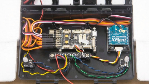
While having an airborne router to extend the range of your penetration test is useful, having a fully-functional aerial hacking drone is even better. In this section a complete hacking system that can be installed entirely on the flight controller (brain) cover of the QuadShot is presented. The drone features a BeagleBone Black, Xbee radio, and Alfa wireless adapter. Power is supplied by the QuadShot battery.
The first step in building the AirDeck is to place a BeagleBone Black on top of the controller board lid in the approximate position shown in Figure 9.6 and then mark the location of the four mounting holes of the BeagleBone. A 1/8 in. drill bit can be used to mark the hole locations if turned by hand. Resist the temptation to use the BeagleBone as a drill template as the board could easily be damaged.
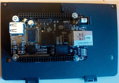
The BeagleBone should be secured to the lid with four 4-40 screws (or similar) and standoffs. Standoffs are required because the lid is slightly curved. Each screw should have three nuts installed. One nut is installed on the outside of the lid to secure the screw to the lid. Then standoffs are installed, followed by the BeagleBone, and finally the two nuts. Two nuts are used to prevent vibrations from spinning the nuts off. Alternatively, lock nuts could be used.
Once the BeagleBone has been successfully test fit it should be removed to protect it from possible damage while installing the Alfa wireless adapter inside the cover. Remove the outside cover on the Alfa adapter. This is easily done with a small screwdriver. Test fit the Alfa and mark the approximate location for the 3/8 in. hole for the antenna by turning the antenna away from the lid and placing the Alfa in approximately the position shown in Figure 9.7.
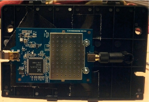
With the Alfa in position, mark the location of the 3/8 in. hole for the antenna. Drill the hole then turn the antenna around so it goes through the hole as shown in Figure 9.7. Mark the two mounting holes then drill 1/8 in. holes. Affix black tape to the screw heads for the BeagleBone mounting screws before installing the Alfa to prevent shorting. Attach the Alfa with 4-40 screws and nuts or similar. Cover the Alfa with black tape to prevent the possibility of it shorting against the LIA board.
Notches must be cut on either side of the cover with a rotary tool. The notch locations can be seen in Figure 9.7. One notch is for the USB cable that runs between the Alfa and the BeagleBone. The other one is for the power cable between the LIA controller board and the BeagleBone.
Power is supplied to the BeagleBone via a 2.1 × 5.5 mm barrel connector attached to the LIA board. The center conductor should be connected to Vcc (5 V) on the LIA board. The outside of the barrel is connected to the LIA ground. UART connectors on the upper left of the LIA are a good choice for these power connections.
Now that the hacking system is complete the lid can be installed on the QuadShot. A short USB cable should be used to connect the Alfa to the BeagleBone. You may need to cut away some of the hard plastic on the Alfa end of the USB cable in order to make the tight bend. Install an appropriate Xbee adapter in an Xbee cape then attach it to the BeagleBone. The full cape is recommended over the mini-cape as it is held more firmly to the BeagleBone thanks to having more pins. The cape should be safetied with a zip tie (just in case) as shown in Figure 9.8.
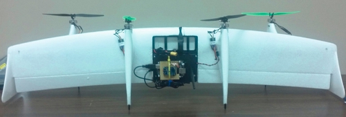
Upon plugging the barrel connector into the BeagleBone the hacking system is complete. The AirDeck is now ready for use. It is strongly recommended that you fly the QuadShot for several hours without the hacking hardware installed before adding the AirDeck. The AirDeck adds extra weight and drag which makes the QuadShot slightly harder to fly. A complete system is shown in Figure 9.9.
Using Your Aerial Drone
Router-only Operation
The simplest use of an aerial drone is to use the Xbee router to extend the range of a penetration test. This can be done with either a router-only or full drone. That said, carrying the extra weight of the BeagleBone and Alfa without using their functionality is foolish. The power required to run the BeagleBone will also drain the batteries much quicker than the router alone.
In the ideal case the QuadShot with router can be landed nearby the target and used for an extended period of time. A flat roof makes the perfect landing spot. In the event that you crash on the roof, you can likely get away with asking the company to retrieve your toy as it does not look suspicious. Of course, it is a good idea to practice flying the QuadShot and landing it on roofs before taking it along on a penetration test.
If there is no place to safely land the QuadShot it could orbit the target. This is not a very practical solution, however, given that the flight time of the QuadShot is under twenty minutes. In addition, orbiting a target with a 4-motor RC aircraft is not terribly subtle.
Using the AirDeck
Sometimes drones are not easily planted in and around a target. The organization's office might be inside a secure fence with guards at the gates. Even if you are able to get access to the outside of the building, it may be under constant surveillance or lack any practical hiding places for drones. In these cases a single AirDeck might be the only practical solution. As with the router-only option, landing the AirDeck on a flat roof is a good choice.
Even if you are able to plant drones in and around your target, the AirDeck can still be a useful addition to a penetration test. Your drones might have only the low power Xbee modems and the AirDeck can operate as a router (in addition to being used as a hacking drone) in order to extend the range of the test. If you can park a car with a drone near the target, the AirDeck can be used as a secondary router and will also provide coverage when you move the car periodically to avoid suspicion.
Conserving Power
The LEDs on the QuadShot can be turned off after a certain amount of inactivity in order to increase stealth and conserve power. In order to accomplish this the Toytronics branch of the Paparazzi software which the LIA runs must be downloaded from github.com. Details on how to accomplish this can be found at http://wiki.thequadshot.com/wiki/Software_User_Guide. The steps for doing this on Ubuntu 12.04 are briefly described here.
Installing the Paparazzi software requires the installation of a cross-compiler and some other tools. According to the Paparazzi wiki (http://wiki.paparazziuav.org/wiki/Installation) everything you need can be installed via a single command on Ubuntu 12.04. The command is as follows:
sudo add-apt-repository ppa:paparazzi-uav/ppa && sudo add-apt-repository \ ppa:terry.guo/gcc-arm-embedded && sudo apt-get update &&\
sudo apt-get install paparazzi-dev gcc-arm-none-eabi && cd ~ && git \ clone https://github.com/paparazzi/paparazzi.git && \
cd ~/paparazzi && git checkout master && sudo cp \ conf/system/udev/rules/50-paparazzi.rules /etc/udev/rules.d/ && \
echo -e "export PAPARAZZI_HOME=~/paparazzi\nexport \PAPARAZZI_ SRC=~/paparazzi" >> ~/.bashrc && source ~/.bashrc && \
make clean && make && ./paparazzi
git clone git@github.com:transition-robotics/paparazzi.git paparazzi
cd paparazii
make clean
make
make AIRCRAFT=QS4_LIA clean_ac ap.compile
Assuming the above build completes successfully, the software can now be modified. The code that controls the QuadShot LEDs can be found in the file led_driver.c located in the sw/airborne/modules/led_driver directory of the Paparazzi software tree. The relevant code is found in the led_driver_periodic method which appears in the listing below. The very last clause in the if-else structure should be modified to turn off the LEDs when the QuadShot has been idle for a while.
void led_driver_periodic(void) {
#ifdef AHRS_ALIGNER_LED
#ifdef AUTOPILOT_LOBATT_BLINK
 if (radio_control.status == RC_LOST || radio_control.status ==RC_REALLY_LOST){
 //RunXTimesEvery(300, 5, 9, {LED_TOGGLE(AHRS_ALIGNER_LED);});
 RunXTimesEvery(0, 60, 5, 7, {LED_TOGGLE(AHRS_ALIGNER_LED);});
 RunXTimesEvery(130, 130, 10, 6, {LED_TOGGLE(AHRS_ALIGNER_LED);});
 }
 else if (ahrs_aligner.status == AHRS_ALIGNER_FROZEN){
 //RunXTimesEvery(0, 120, 5, 4, {LED_TOGGLE(AHRS_ALIGNER_LED);});
 RunXTimesEvery(5, 200, 10, 20, {LED_ON(AHRS_ALIGNER_LED);});
 RunXTimesEvery(0, 200, 10, 20, {LED_OFF(AHRS_ALIGNER_LED);});
 }
 else if (autopilot_first_boot){
 //RunXTimesEvery(0, 120, 5, 4, {LED_TOGGLE(AHRS_ALIGNER_LED);});
 RunXTimesEvery(5, 120, 10, 2, {LED_ON(AHRS_ALIGNER_LED);});
 RunXTimesEvery(0, 120, 10, 2, {LED_OFF(AHRS_ALIGNER_LED);});
 }
 else if (autopilot_safety_violation_mode){
 //RunXTimesEvery(0, 240, 20, 2, {LED_TOGGLE(AHRS_ALIGNER_LED);});
 RunXTimesEvery(20, 240, 40, 1, {LED_ON(AHRS_ALIGNER_LED);});
 RunXTimesEvery(0, 240, 40, 1, {LED_OFF(AHRS_ALIGNER_LED);});
 }
 else if (autopilot_safety_violation_throttle){
 //RunXTimesEvery(0, 240, 20, 4, {LED_TOGGLE(AHRS_ALIGNER_LED);});
 RunXTimesEvery(20, 240, 40, 2, {LED_ON(AHRS_ALIGNER_LED);});
 RunXTimesEvery(0, 240, 40, 2, {LED_OFF(AHRS_ALIGNER_LED);});
 }
 else if (autopilot_safety_violation_roll){
 //RunXTimesEvery(0, 240, 20, 6, {LED_TOGGLE(AHRS_ALIGNER_LED);});
 RunXTimesEvery(20, 240, 40, 3, {LED_ON(AHRS_ALIGNER_LED);});
 RunXTimesEvery(0, 240, 40, 3, {LED_OFF(AHRS_ALIGNER_LED);});
 }
 else if (autopilot_safety_violation_pitch){
 //RunXTimesEvery(0, 240, 20, 8, {LED_TOGGLE(AHRS_ALIGNER_LED);});
 RunXTimesEvery(20, 240, 40, 4, {LED_ON(AHRS_ALIGNER_LED);});
 RunXTimesEvery(0, 240, 40, 4, {LED_OFF(AHRS_ALIGNER_LED);});
 }
 else if (autopilot_safety_violation_yaw){
 //RunXTimesEvery(0, 240, 20,10, {LED_TOGGLE(AHRS_ALIGNER_LED);});
 RunXTimesEvery(20, 240, 40, 5, {LED_ON(AHRS_ALIGNER_LED);});
 RunXTimesEvery(0, 240, 40, 5, {LED_OFF(AHRS_ALIGNER_LED);});
 }
 else if (autopilot_safety_violation){
 RunOnceEvery(5, {LED_TOGGLE(AHRS_ALIGNER_LED);});
 }
 else if (electrical.vsupply < (MIN_BAT_LEVEL * 10)){
 RunOnceEvery(20, {LED_TOGGLE(AHRS_ALIGNER_LED);});
 }
 else if (electrical.vsupply < ((MIN_BAT_LEVEL + 0.5) * 10)){
 RunXTimesEvery(0, 300, 10, 10, {LED_TOGGLE(AHRS_ALIGNER_LED);});
 }
 else { // THIS IS THE CLAUSE TO MODIFY
 LED_ON(AHRS_ALIGNER_LED);
 }
#endif
#endif
}
There are several choices on how you can turn off the LEDs. One simple option is to just turn them off all the time when everything is good by changing LED_ON(AHRS_ALIGNER_LED) to LED_OFF(AHRS_ALIGNER_LED) in the else clause from the code segment above. There is a real downside of doing this. The LEDs are there for a reason: to help you orient the QuadShot. A simple solution would be to turn off the LEDs if communication with the radio is lost which would allow you to just switch off the remote control to switch off the LEDs. Alternatively, you could use a timer to extinguish the LEDs after a time of inactivity.
To conserve power, the LIA board could be put to sleep after a time of inactivity. The board could then be awakened periodically to check for a signal from the remote control. This would require modifying the main method of the Paparazzi software. This modification is left as an exercise for the reader.
Alternative Aircraft
The aircraft just presented is only one option. The BeagleBone Black is small, lightweight, and consumes little power. As a result, a drone can be attached to a number of aircraft.
Quadcopter
While I opted for the QuadShot over a quadcopter, some might prefer to use a multicopter. There are some very capable multicopters available, such as the DJI Phantom. Glenn Wilkinson and Daniel Cuthbert of Sensepost have used the Phantom to deploy their Snoopy distributed tracking and profiling by air (http://research.sensepost.com/conferences/2012/distributed_tracking_and_profiling_framework). The Phantom has a flight time of 10-15 min. The Phantom is approximately three times the price of the QuadShot making it out of reach for some.
Other multicopters would likely work. Be careful when selecting your own aircraft. The chosen airframe must be capable of lifting the weight of a BeagleBone Black, Xbee radio, and Alfa adapter in order to be useful. Some of the cheaper options have no payload capability beyond the aircraft itself. Additionally, many affordable quadcopters cannot be operated outdoors thanks to limited ability to fly in wind.
An Improved Flying Wing
The aerial drone based on the QuadShot described in this chapter has the advantage of simplicity. It is also easily attached and removed from the QuadShot. One disadvantage of this device is that there is no meaningful communication between the LIA and BeagleBone Black. Because the boards do not talk to each other they both must be on all the time.
The BeagleBone Black with its 1 GHz ARM Cortex A8 can easily perform all of the functions of the 72 MHz microcontroller found on the LIA board while still being used for other tasks. The BeagleBone also has more than enough Pulse Width Modulation (PWM) and General Purpose Input /Output (GPIO) to emulate the LIA. PWM is used to drive servos attached to the LIA. A full discussion on PWM and driving servos with the BeagleBone Black is beyond the scope of this book. You can find a tutorial at the AdaFruit website here http://learn.adafruit.com/controlling-a-servo-with-a-beaglebone-black/overview.
The QuadShot autopilot requires one more component: an Inertial Measurement Unit (IMU). Transition Robotics sells an IMU known as the Aspirin that is featured in several of the boards they sell, including the LIA. The Aspirin features a gyroscope, magnetometer, accelerometer, EEPROM, and barometer (for determining altitude). The Aspirin uses the industry standard Inter-Integrated Circuit (I2C) and Serial Peripheral Interface (SPI) communication protocols.
Direct connections between the servos and BeagleBone and the IMU and BeagleBone could be used. Creating at simple shield would result in a cleaner and more robust solution, however. This functionality could easily be added to the Xbee cape described in an earlier chapter. Developing this cape is left as an exercise to the reader.
Once the hardware is in place, the Paparazzi software must be modified to work with the appropriate PWM and GPIO pins on the BeagleBone as opposed to the LIA board. The I2C and SPI modules would also require changes to work with the BeagleBone. The software controlling the I2C and SPI communications with the STM32 microcontroller on the LIA can be found in the sw/airborne/arch/stm32/mcu_periph directory. Equivalent code for the BeagleBone would need to be written.
Creating a version of the QuadShot based on the BeagleBone is a bit of work. The benefits of doing so go well beyond saving power by running a single board, however. The BeagleBone has sufficient computing power to allow more autonomous operations. Examples include orbiting a target at constant altitude, and popping the QuadShot into the air if it is approached (an infrared sensor would be required).
With the addition of a GPS the possibilities expand greatly. The QuadShot could be programmed to fly a predetermined flight path to the target, return home when it is approached, or return when the batteries begin to run low. A ping sensor or camera could also be used to assist with landings.
Summary
In this chapter we discussed an easily constructed flying wing platform that could be used as an aerial hacking drone. We also talked about other possibilities such as attaching hacking hardware to a quadcopter. We ended the chapter with thoughts on how to improve the flying wing presented earlier in the chapter.
We are rapidly approaching the end of this book. In the next chapter some current efforts to expand upon what has been presented here and some possible future directions will be discussed.