Step 4: Connecting the Electronics

At this point we have the equivalent of a car with no ignition and no power. We have our three motor trays, but we need something that can control them and make them move. An “Arduino” is an electronic microcontroller that is very simple to use even for beginners. It can be used to control lots of different electronic components, such as LEDs, LCDs, buttons, sensors, switches, and, in our case, stepper motors. While the Arduino has the ability to control the stepper motors, it doesn’t have the capacity to provide enough energy to power them. To fix that problem, we will need what’s known as a stepper motor “driver” for each motor. In the diagrams, you can see how to wire up each motor driver for each axis.

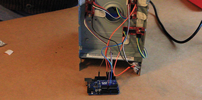
You may have noted that the motor drivers have two connections that are supposed to go to a “power supply.” This is a power source that provides extra power. Since I’m mostly using parts from scavenged computers, my power source is going to be an old computer (ATX) power supply. A computer power supply can output several different specific types of voltage. Despite their usefulness, let me warn you that computer power supplies can be dangerous if you mess with them and don’t know what you’re doing. Please use caution when utilizing them.
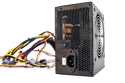

When being used inside of a computer, a computer power supply turns on and off whenever you press a power button. In order to use a computer power supply without a power button, we need to bypass its power switch detection. Most common ATX computer power supplies have either twenty or twenty-four pins. Depending on which version you have, you can use the guide to determine where the “PC-ON” and ground pins are located. Then connect a ground pin to the “PC-ON” pin using a scrap piece of wire. Once the switch detection is bypassed, you can also use this wiring diagram to determine where the ground and 5v pins are so that you can connect them to the motor drivers. This is what we will be using to power our motors.
Step 5: Hacking the 3D Pen
The essence of most hobby 3D printers is the ability to melt plastic filament and extrude it into layers. This requires a device known
as a “hot end” that takes plastic filament, melts it, and outputs it onto a platform. There are a lot of commercial grade “hot ends”
on the market, but they can be somewhat expensive, and they’re kind of overkill given the homely nature of our build. Initially, I wanted to make my own “hot end,” but it ended up being a difficult thing to fabricate at home. So what I did instead was purchase a cheap 3D printing pen to see if I could tweak it and make it work as the “hot end.”
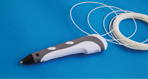
The 3D printing pen I purchased was a very simple device. You plug it in, turn it on, insert the plastic filament, and then press a button to melt the filament and extrude it out the nozzle end. Testing it out, I found it worked as advertised.


Now I just need to find a way to control it with the Arduino. Since it requires only the press of a button to melt and extrude the plastic, if we can trigger that button with the Arduino, then we should be able to program when it extrudes the plastic and when it doesn’t.

What we want to do is switch the button on and
off using an electrical signal. The best tool for doing that is a transistor, a device which switches electrical power off and on. In this case, I’ll be using an NPN transistor. Taking apart the 3D pen, I found where the extrude button was connected to the main circuit board. We can connect the Arduino to the NPN transistor, and then connect the NPN transistor to either side of the button. Since the Arduino outputs five volts of power and that might be too much power for the button, I added a twenty-two ohm resistor to limit the power. Depending on what 3D pen you use, the resistance may change.

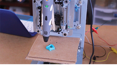
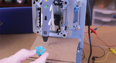
After reassembling the 3D pen and making a space for the wires to run through the casing, I mounted it to the Z axis sliding motor tray. You could use wire, bolts, and spacers, but what I ended up using was hot glue to hold it into place. Now, we’ve got the bones of our 3D printer! Next, we need to make it print something.


Step 6: The Software
This 3D printer, as well as most other 3D printers and CNC machines, runs off of a programming language called “G-code.” It essentially tells the X, Y, and Z axis which specific coordinates it needs to go to in order to make lines and arcs. G-Code is how a 3D printer knows what to create. If you want to 3D print a cube, the instructions for how to build that cube are converted into G-code and sent to the 3D printer. By itself, Arduino has a difficult time interpreting G-code, so we will need to install a G-code interpreter program called “Grbl.” You can download the version of Grbl specific to your Arduino model from GitHub4 and load it to your Arduino using a utility called “Xloader”5.

The Arduino is now ready to accept G-code and send those instructions to our 3D printer motors. The final piece of software we need is something that takes a 3D G-code file and sends those commands to the Arduino. I stumbled across a simple Windows only program called “Grbl Controller.”6 After downloading and installing the program, connect your Arduino to your computer and launch. You can select your Arduino COM port number from the “Port Name” drop-down box, and then click “Open” to connect to it.
Now you can use the arrows on the lower right to jog through the motors. The drop-down box in the lower right corner sets the movement speed. Make sure the speed setting is set to one instead of ten. If any of the platforms are running backward, you can go to Tools > Options and then invert the axis for the backward motor.
Once everything is powered up and running, the final step is finding something to print. Since this 3D printer is very specialized, I had to create the G-code by hand, and you can download the samples I made to 3D print on your own machine7. If everything goes well, you should see all the motors move and the 3D pen will start creating 3D objects!

What can I say about smartphones? They’re portable and pocket-sized, they’ve revolutionized the way we communicate and connect with each other online, they’ve made it easier to document our lives through photo and video, and they entice us to upgrade by coming out with something better and faster every year. Because of that last point, there are so many smartphones lying around going to waste. Although smartphones are currently the predominant mobile device, that wasn’t always the case. Believe it or not, older mobile devices didn’t connect to the internet. Instead of having everything on one device such as contact lists, music players, and ability to call, these activities all used to be on separate devices. Anyone remember pagers, flip phones, PDAs, and stand-alone MP3 players? Yeah, those were the days.
The great thing about upcycling old mobile devices is that they are…mobile. This means that they are great for making portable projects. The older mobile devices generally have to be modded or taken apart to make something new, but smartphones, especially Android phones, can easily be repurposed just by adding or creating new useful apps! The following chapter has three projects ranging from easy to advanced, and it centers around upcycling different types of mobile devices.