Chapter III
Reciprocating Engine Theory of Operation
Reciprocating Gasoline Engine Operating Principles
A study of this section will help in understanding the basic operating principles of reciprocating engines. The principles that govern the relationship between the pressure, volume, and temperature of gases is primary to understanding engine operation.
An internal-combustion engine is a device for converting chemical energy of fuel into heat energy, then into mechanical energy. Gasoline is vaporized and mixed with air, forced or drawn into a cylinder, compressed by a piston, and then ignited by an electric spark. The conversion of the resultant heat energy into mechanical energy and then into work is accomplished within the cylinder. Figure 3-1 illustrates the various engine components necessary to accomplish this conversion and also presents the principal terms associated with engine operation.

Figure 3-1. Components and terminology of engine operation.
The operating cycle of an internal combustion reciprocating engine includes the series of events required to induct, compress, ignite, burn, expand the fuel/air charge in the cylinder, and to exhaust the by-products of the combustion process.
When the compressed mixture of fuel and air is ignited, the resultant gases of combustion expand very rapidly and force the piston to move away from the cylinder head. This downward motion of the piston, acting on the crankshaft through the connecting rod, is converted to a circular or rotary motion by the crankshaft.
A valve in the top or head of the cylinder opens to allow the burned gases to escape, and the momentum of the crankshaft and the propeller forces the piston back up in the cylinder where it is ready for the next event in the cycle. The intake valve in the cylinder head then opens to let in a fresh charge of the fuel/air mixture.
The valve allowing for the escape of the burning exhaust gases is called the exhaust valve, and the valve that lets in the fresh charge of the fuel/air mixture is called the intake valve. These valves are opened and closed mechanically at the proper times by the valve-operating mechanism.
The bore of a cylinder is its inside diameter. The stroke is the distance the piston moves from one end of the cylinder to the other—specifically, from top dead center (TDC) to bottom dead center (BDC), or vice versa (see figure 3-1).
Operating Cycles
There are two operating cycles in general use: (1) the two-stroke cycle and (2) the four-stroke cycle. At the present time, except for a few very light aircraft, the two-stroke-cycle engine is fast disappearing from the aviation scene. As the name implies, two-stroke-cycle engines require only one upstroke and one downstroke of the piston to complete the required series of events in the cylinder. Thus the engine completes the operating cycle in one revolution of the crankshaft.
Four-Stroke Cycle
Most aircraft reciprocating engines operate on the four-stroke cycle, sometimes called the Otto cycle after its originator, a German physicist. The four-stroke-cycle engine has many advantages for use in aircraft. One advantage is that it lends itself readily to high performance through supercharging.
In this type of engine, four strokes are required to complete the required series of events or operating cycle of each cylinder, as shown in figure 3-2. Two complete revolutions of the crankshaft (720°) are required for the four strokes; thus, each cylinder in an engine of this type fires once in every two revolutions of the crankshaft.

Figure 3-2. Four-stroke cycle.
In the following discussion of the four-stroke cycle engine operation, it should be realized that the timing of the ignition and the valve events will vary considerably in different engines. Many factors influence the timing of a specific engine, and it is most important that the engine manufacturer’s recommendations in this respect be followed in maintenance and overhaul. The timing of the valve and ignition events is always specified in degrees of crankshaft travel.
In the following paragraphs, the timing of each event is specified in terms of degrees of crankshaft travel on the stroke during which the event occurs. It should be remembered that a certain amount of crankshaft travel is required to open a valve fully; therefore, the specified timing represents the start of opening rather than the full-open position of the valve.
Intake Stroke
During the intake stroke, the piston is pulled downward in the cylinder by the rotation of the crankshaft. This reduces the pressure in the cylinder and causes air under atmospheric pressure to flow through the carburetor, which meters the correct amount of fuel. The fuel/air mixture passes through the intake manifold pipes and intake valves into the cylinders. The quantity or weight of the fuel/air charge depends upon the degree of throttle opening.
The intake valve is opened considerably before the piston reaches top dead center on the exhaust stroke, in order to induce a greater quantity of the fuel/air charge into the cylinder and thus increase the horsepower. The distance the valve may be opened before top dead center, however, is limited by several factors, such as the possibility that hot gases remaining in the cylinder from the previous cycle may flash back into the intake manifold, burning the fuel/air mixture in the induction system (backfire).
In all high-power aircraft engines, both the intake and the exhaust valves are off the valve seats at top dead center at the start of the intake stroke. As mentioned above, the intake valve opens before top dead center on the exhaust stroke (valve lead), and the closing of the exhaust valve is delayed considerably after the piston has passed top dead center and has started the intake stroke (valve lag). This timing is called valve overlap and is designed to aid in cooling the cylinder internally by circulating the cool incoming fuel/air mixture, to increase the amount of the fuel/air mixture induced into the cylinder, and to aid in scavenging the by-products of combustion.
The intake valve is timed to close about 50° to 75° past bottom dead center on the compression stroke depending upon the specific engine, to allow the momentum of the incoming gases to charge the cylinder more completely. Because of the comparatively large volume of the cylinder above the piston when the piston is near bottom dead center, the slight upward travel of the piston during this time does not have a great effect on the incoming flow of gases. This late timing can be carried too far because the gases may be forced back through the intake valve and defeat the purpose of the late closing.
Compression Stroke
After the intake valve is closed, the continued upward travel of the piston compresses the fuel/air mixture to obtain the desired burning and expansion characteristics.
The charge is fired by means of an electric spark as the piston approaches top dead center. The time of ignition will vary from 20° to 35° before top dead center, depending upon the requirements of the specific engine, to ensure complete combustion of the charge by the time the piston is slightly past the top dead center position.
Many factors affect ignition timing, and the engine manufacturer has expended considerable time in research and testing to determine the best setting. All engines incorporate devices for adjusting the ignition timing, and it is most important that the ignition system be timed according to the engine manufacturer’s recommendations.
Power Stroke
As the piston moves through the top dead center position at the end of the compression stroke and starts down on the power stroke, it is pushed downward by the rapid expansion of the burning gases within the cylinder head with a force that can be greater than 15 tons (30,000 psi) at maximum power output of the engine. The temperature of these burning gases may be between 3,000° and 4,000° F.
As the piston is forced downward during the power stroke by the pressure of the burning gases exerted upon it, the downward movement of the connecting rod is changed to rotary motion by the crankshaft. Then the rotary movement is transmitted to the propeller shaft to drive the propeller. As the burning gases expand and the downward movement of the piston causes increased volume of the chamber, the temperature drops to within safe limits before the exhaust gases flow out through the exhaust port.
Valve Timing
The timing of the exhaust valve opening is determined by, among other considerations, the desirability of using as much of the expansive force as possible and of scavenging the cylinder as completely and rapidly as possible. The valve is opened considerably before bottom dead center on the power stroke (on some engines at 50° to 75° before BDC) while there is still some pressure in the cylinder. This timing is used so that the pressure can start moving gases out of the exhaust port as soon as possible. This process frees the cylinder of waste heat after the desired expansion has been obtained and avoids overheating the cylinder and the piston. Thorough scavenging of exhaust gases is very important, because any exhaust products remaining in the cylinder will dilute the incoming fuel/air charge at the start of the next cycle.
Exhaust Stroke
As the piston travels through bottom dead center at the completion of the power stroke, and starts upward on the exhaust stroke, it will begin to push the burned exhaust gases out the exhaust port. Near the end of the exhaust stroke, the speed of the exhaust gases leaving the cylinder creates a low pressure in the cylinder. This low or reduced pressure speeds the flow of the fresh fuel/air charge into the cylinder as the intake valve is beginning to open. The intake valve opening is timed to occur at 8° to 55° before top dead center on the exhaust stroke on various engines.
Engine Power and Efficiency
All aircraft engines are rated according to their ability to do work and produce power. This section presents an explanation of work and power and how they are calculated. Also discussed are the various efficiencies that govern the power output of a reciprocating engine.
Work
In physics, work is force times distance. Work done by a force acting on a body is equal to the magnitude of the force multiplied by the distance through which the force acts.
Work (W) = Force (F) × Distance (D)
Work is measured by several standards, the most common English system unit is called the foot-pound. If a 1-pound mass is raised 1 foot, 1 foot-pound (ft-lb) of work has been performed. The greater the mass and the greater the distance, the greater the work.
Horsepower
The common English system unit of mechanical power is the horsepower (HP). Late in the 18th century, James Watt, the inventor of the steam engine, found that an English workhorse could work at the rate of 550 ft-lb per second, or 33,000 ft-lb per minute, for a reasonable length of time. To calculate the HP rating of an engine, divide the power developed in ft-lb per minute by 33,000, or the power in ft-lb per second by 550.
HP = ft-lb per min ÷ 33,000
or
HP = ft-lb per sec ÷ 550
Work is performed not only when a force is applied for lifting; force may be applied in any direction. If a 100-lb weight is dragged along the ground, a force is still being applied to perform work, although the direction of the resulting motion is approximately horizontal. The amount of this force would depend upon the roughness of the ground.
If the weight were attached to a spring scale graduated in pounds, then dragged by pulling on the scale handle, the amount of force required could be measured. Assume that the force required is 90 lbs, and the 100-lb weight is dragged 660 ft in 2 min. The amount of work performed in the 2 min will be 59,400 ft-lb or 29,700 ft-lb per min. Since 1 HP is 33,000 ft-lb per min, the HP expended in this case will be 29,700 divided by 33,000 or 0.9 HP.
If a 4,000-pound airplane was climbing 1,000 ft/min at a true airspeed of 100 knots while experiencing 600 pounds of total drag, the power required would be:
Power required to overcome drag:
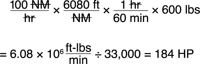
Power required to climb:

Total power required:
184 HP + 121 HP = 305 HP
Piston Displacement
When other factors remain equal, the greater the piston displacement the greater the maximum horsepower an engine will be capable of developing. When a piston moves from bottom dead center to top dead center, it displaces a specific volume. The volume displaced by the piston is known as piston displacement and is expressed in cubic inches for most American-made engines and cubic centimeters for others.
The piston displacement of one cylinder may be obtained by multiplying the area of the cross section of the cylinder by the total distance the piston moves in the cylinder in one stroke. For multi-cylinder engines this product is multiplied by the number of cylinders to get the total piston displacement of the engine.
Since the volume (V) of a geometric cylinder equals the area (A) of the base multiplied by the height (H), it is expressed mathematically as:
V = A × H
The area of the base (A) is the area of the piston top, and height (H) is equal to the length of the piston stroke.
Example:
Compute the piston displacement of the PWA 14-cylinder engine having a cylinder with a 5.5-inch diameter and a 5.5-inch stroke. Formulas required are:
R = D ÷ 2
A = πR2
V = A × H
Total V = V × N (number of cylinders)
Substitute values into these formulas and complete the calculation.
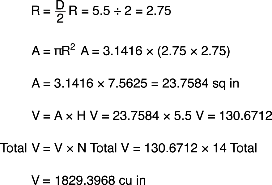
Rounded off to the next whole number, total piston displacement equals 1,830 cu in.
Compression Ratio
All internal-combustion engines must compress the fuel/air mixture to receive a reasonable amount of work from each power stroke. The fuel/air charge in the cylinder can be compared to a coil spring, in that the more it is compressed, the more work it is potentially capable of doing, because combustion is a chemical reaction (see Chapter 6), and chemical reactions occur more quickly and completely if the reacting materials are closer together (high pressure) and more physically active (higher temperature).
The compression ratio of an engine (see figure 3-3) is a comparison of the volume of space in a cylinder when the piston is at the bottom of the stroke to the volume of space when the piston is at the top of the stroke. This comparison is expressed as a ratio, hence the term “compression ratio.” Compression ratio is a controlling factor in the maximum horsepower developed by an engine, but it is limited by present-day fuel grades and the high engine speeds and manifold pressures required for takeoff. For example, if there are 140 cu in. of space in the cylinder when the piston is at the bottom and there are 20 cu in. of space when the piston is at the top of the stroke, the compression ratio would be 140 to 20. If this ratio is expressed in fraction form, it would be 140/20, or 7 to 1, usually represented as 7:1.
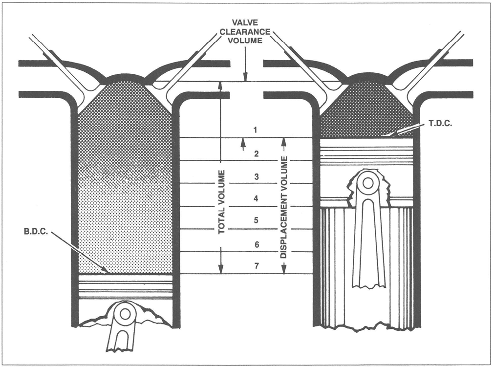
Figure 3-3. Compression ratio.
Generally it can be said that, within limits of proper engine operation, the higher the engine compression ratio, the higher will be engine efficiency (and horsepower output).
Manifold Absolute Pressure (MAP)
To grasp more thoroughly the limitation placed on compression ratios, manifold pressure and its effect on compression pressures should be understood. Manifold pressure is the average absolute pressure of the air or fuel/air charge in the intake manifold and is measured in units of inches of mercury (Hg). Manifold pressure is dependent mostly on ambient air pressure, engine speed, throttle setting and supercharging.
Compression ratio and manifold pressure determine the pressure in the cylinder in that portion of the operating cycle when both valves are closed. The pressure of the charge before compression is determined by manifold pressure, while the pressure at the height of compression (just prior to ignition) is determined by manifold pressure times the compression ratio. For example, if an engine were operating at a manifold pressure of 30" Hg with a compression ratio of 7:1, the pressure at the instant before ignition would be approximately 210" Hg. However, at a manifold pressure of 60" Hg, the pressure would be 420" Hg.
Without going into great detail, it has been shown that the compression event magnifies the effect of varying the manifold pressure, and the magnitude of both affects the pressure of the fuel charge just before the instant of ignition. If the pressure at this time becomes too high, premature ignition (preignition) or knock will occur and produce overheating.
One of the reasons for using engines with high compression ratios is to obtain long-range fuel economy—that is, to convert more heat energy into useful work than is done in engines of low compression ratio. Since more heat of the charge is converted into useful work, less heat is absorbed by the cylinder walls. This factor promotes cooler engine operation, which in turn increases the thermal efficiency.
Here, again, a compromise is needed between the demand for fuel economy and the demand for maximum horsepower without knocking. Some manufacturers of high-compression engines suppress knock at high manifold pressures by injecting an antiknock fluid into the fuel/air mixture. The injection of a water/alcohol mix decreases peak temperatures and pressures at takeoff power settings but increases average pressures and, therefore, increases power output for short periods, such as at takeoff and during emergencies, when power is critical.
Absolute and Gauge Pressure
The word absolute in the term manifold absolute pressure (MAP) identifies the pressure measurement as one that is based on a comparison of the pressure in the manifold with pressure at absolute zero (no pressure at all). The other method of measuring pressure, called gauge pressure, compares the pressure being measured against ambient pressure. As an example, the pressure in an aircraft’s tire measured at sea level is 32 psig; Tire gauges measure “gauge” pressure, so the pressure in the tire is 32 psi higher than atmospheric pressure, which is 14.7 psi (standard day sea level). The absolute pressure of the tire would be 32 + 14.7 = 46.7 psia. If that tire’s pressure is measured at the same tire temperature but at progressively higher altitudes, the psig would increase but the psia would remain the same.
Indicated Horsepower
The indicated horsepower produced by an engine is the horsepower calculated from the indicated mean effective pressure and the other factors that affect the power output of an engine. Indicated horsepower (IHP) is the power developed in the combustion chambers without reference to friction losses within the engine. In the pilot’s mind, IHP should be separated from brake horsepower, which will be discussed shortly.
Indicated horsepower is calculated as a function of the actual cylinder pressure recorded during engine operation. To facilitate the indicated horsepower calculations, a mechanical indicating device, attached to the engine cylinder, scribes the actual pressure existing in the cylinder during the complete operating cycle. This pressure variation can be represented by the kind of graph shown in figure 3-4. Notice that the cylinder pressure rises on the compression stroke, reaches a peak after ignition, then decreases as the piston moves down on the power stroke.

Figure 3-4. Cylinder pressure during power cycle.
To arrive at the total pressure exerted on the piston head, one can integrate the instantaneous values of pressure (that are above ambient pressure) for the duration of the power stroke. For those of us who are not into calculus, it can be said that the area under the pressure curve (during the power stroke) is directly proportional to the total force applied to the piston head. From this must be subtracted the area below the ambient pressure line because ambient pressure is pushing up on the bottom of the piston since ambient pressure exists in the crankcase.
Since the cylinder pressure varies during the operating cycle, an average pressure, line AB, is computed. This average pressure, if applied steadily during the time of the power stroke, would do the same amount of work as the varying pressure during the same period.
The area under the average pressure line equals the area under the actual pressure curve minus the area under the ambient pressure curve. The decrease of ambient pressure as the aircraft flies at higher altitudes is one of the reasons why an engine will produce more power at altitude if all else (including MAP) remains the same. Other reasons for this phenomena include lower exhaust back pressure at altitude (which provides better removal of exhaust gases resulting in more fuel/air mixture entering for the next power stroke) and usually colder temperatures at altitude (which increases the number of oxygen molecules that can be packed into each cylinder).
This average pressure is known as indicated mean effective pressure and is included in the indicated horsepower calculation with other engine specifications. If the characteristics and the indicated mean effective pressure of an engine are known, it is possible to calculate the indicated horsepower rating.
The indicated horsepower for a four-stroke-cycle engine can be calculated from the following formula, in which the letter symbols in the numerator are arranged to spell the word “plank” to assist in memorizing the formula:
IHP = PLANK ÷ 33,000
Where:
P = Indicated mean effective pressure in psi
L = Length of the stroke in ft or in fractions of a foot
A = Area of the piston head or cross-sectional area of the cylinder, in sq in.
N = Number of power strokes per minute; RPM ÷ 2
K = Number of cylinders
In the formula above, the area of the piston times the indicated mean effective pressure gives the force acting on the piston in pounds. This force multiplied by the length of the stroke in feet gives the work performed in one power stroke, which, multiplied by the number of power strokes per minute, gives the number of ft-lb per minute of work produced by one cylinder. Multiplying this result by the number of cylinders in the engine gives the amount of work performed, in ft-lb, by the engine. Since HP is defined as work done at the rate of 33,000 ft-lb per min., the total number of ft-lb of work performed by the engine is divided by 33,000 to find the indicated horsepower.
The above formula’s main value to pilots is that it provides a sense of the factors that provide power output from a piston engine.
Example :
Given:
Indicated mean effective pressure (P) = 165 lbs/sq in
Stroke (L) = 6 in or .5 ft
Bore = 5.5 in
RPM = 3,000
No. of cylinders (K) = 12
IHP = PLANK ÷ 33,000 ft-lbs/min
Find IHP:
A is found by using the equation
A = ¼πD2
A = ¼ × 3.1416 × 5.5 × 5.5
= 23.76 sq in.
N is found by multiplying the RPM by 1/2:
N = ½ × 3,000
= 1,500 RPM
Now, substituting in the formula:
Indicated HP = (165 × .5 × 23.76 ×1,500 ×12) ÷ (33,000 ft-lbs/min)
= 1, 069.20 HP
Brake Horsepower
The indicated horsepower calculation discussed in the preceding paragraph is the theoretical power of a frictionless engine. The total horsepower lost in overcoming friction must be subtracted from the indicated horsepower to arrive at the actual horsepower delivered to the propeller. The power delivered to the propeller for useful work is known as brake horsepower (BHP). The difference between indicated and brake horsepower is known as friction horsepower, which is the horsepower required to overcome mechanical losses such as the pumping action of the pistons, the pistons and the friction of all moving parts and the power needed to operate accessories (magnetos, pumps, etc.).
In practice, the measurement of an engine’s BHP involves the measurement of a quantity known as torque, or twisting moment. Torque is the product of a force and the distance of the force from the axis about which it acts, or
Torque = Force times Distance
(at right angles to the force).
Torque is a measure of load and is properly expressed in pound-inches (lb-in) or pound-feet (lb-ft) and should not be confused with work, which is expressed in inch-pounds (in-lbs) or foot-pounds (ft-lbs).
There are a number of devices for measuring torque, of which the Prony brake, dynamometer, and torquemeter are examples. Typical of these devices is the Prony brake (figure 3-5), which measures the usable power output of an engine on a test stand. It consists essentially of a hinged collar, or brake, which can be clamped to a drum splined to the propeller shaft. The collar and drum form a friction brake, which can be adjusted. An arm of a known length is rigidly attached to or is a part of the hinged collar and terminates at a point which bears on a set of scales. As the propeller shaft rotates, it tends to carry the hinged collar of the brake with it and is prevented from doing so only by the arm that bears on the scale. The scale reads the force necessary to arrest the motion of the arm. If the resulting force registered on the scale is multiplied by the length of the arm, the resulting product is the torque exerted by the rotating shaft. Example: If the scale registers 200 lbs and the length of the arm is 3.18 ft, the torque exerted by the shaft is:
200 lb × 3.18 ft = 636 lb-ft
Once the torque is known, the work done per revolution of the propeller shaft can be computed without difficulty by the equation:
Work per revolution = 2π × torque
If work per revolution is multiplied by the RPM, the result is work per minute, or power. If the work is expressed in ft-lbs per min, this quantity is divided by 33,000; the result is the brake horsepower of the shaft. In other words:
Power = Work per revolution × RPM
BHP = (Work per revolution × RPM) ÷ 33,000
or
BHP = (2π × force on the scales (lbs) × length of arm (ft) × RPM) ÷ 33,000
Example:
Given:
Force on scales = 200 lbs
Length of arm = 3.18 ft
RPM = 3,000
π = 3.1416
Find BHP:
Substituting in equation:
BHP = (6.2832 × 200 × 3.18 × 3,000) ÷ 33,000
= 363.2 BHP
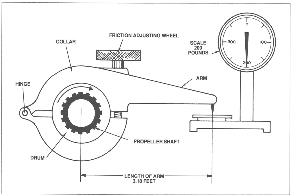
Figure 3-5. Typical Prony brake.
As long as the friction between the brake collar and propeller shaft drum is great enough to impose an appreciable load on the engine, but is not great enough to stop the engine, it is not necessary to know the amount of friction between the collar and drum to compute the BHP. If there were no load imposed, there would be no torque to measure, and the engine would “run away.” If the imposed load is so great that the engine stalls, there may be considerable torque to measure, but there will be no RPM. In either case it is impossible to measure the BHP of the engine. However, if a reasonable amount of friction exists between the brake drum and the collar and the load is then increased, the tendency of the propeller shaft to carry the collar and arm about with it becomes greater, thus imposing a greater force upon the scales. As long as the torque increase is proportional to the RPM decrease, the horsepower delivered at the shaft remains unchanged. This can be seen from the equation in which 2π and 33,000 are constants and torque and RPM are variables. If the change in RPM is inversely proportional to the change in torque, their product will remain unchanged. Therefore, BHP remains unchanged. This is important. It shows that horsepower is the function of both torque and RPM, and can be changed by changing either torque or RPM, or both.
Friction Horsepower
Friction horsepower (FHP) is the indicated horsepower minus brake horsepower. It is the horsepower used by an engine in overcoming the friction of moving parts, drawing in fuel, expelling exhaust, driving oil and fuel pumps, and other accessories. On modern aircraft engines, FHP power may be as high as 10 to 20% of the indicated horsepower.
Friction And Brake Mean Effective Pressures
The indicated mean effective pressure (IMEP), discussed previously, is the average pressure produced in the combustion chamber during the operating cycle and is an expression of the theoretical, frictionless power known as indicated horsepower. In addition to completely disregarding power lost to friction, indicated horsepower gives no indication as to how much actual power is delivered to the propeller shaft for doing useful work. However, it is related to actual pressures which occur in the cylinder and can be used as a measure of these pressures.
To compute the friction loss and net power output, the indicated horsepower of a cylinder may be thought of as two separate powers, each producing a different effect. The first power overcomes internal friction, and the horsepower thus consumed is known as friction horsepower. The second power, known as brake horsepower, produces useful work at the propeller. Logically, therefore, that portion of IMEP that produces brake horsepower is called brake mean effective pressure (BMEP). The remaining pressure used to overcome internal friction is called friction mean effective pressure (FMEP). This is illustrated in figure 3-6. IMEP is a useful expression of total cylinder power output, but is not a real physical quantity; likewise, FMEP and BMEP are theoretical but useful expressions of friction losses and net power output.

Figure 3-6. Powers and pressures.
Although BMEP and FMEP have no real existence in the cylinder, they provide a convenient means of representing pressure limits, or rating engine performance throughout its entire operating range. This is true since there is a relationship between IMEP, BMEP, and FMEP.
One of the basic limitations placed on engine operation is the pressure developed in the cylinder during combustion. In the discussion of compression ratios and indicated mean effective pressure, it was found that, within limits, the increased pressure resulted in increased power. It was also noted that if the cylinder pressure was not controlled within close limits, it would impose dangerous internal loads that might result in engine failure. It is therefore important to have a means of determining these cylinder pressures as a protective measure and for efficient application of power.
If the BHP is known, the BMEP can be computed by means of the following equation:
BMEP = (BHP × 33,000) ÷ LANK
Example:
Given:
BHP = 1,000
Stroke = 6 in.
Bore = 5.5 in.
RPM = 3,000
No. of cyls. = 12
Find BMEP:
Find length of stroke (in feet):
L = 0.5
Find area of cylinder bore:
A = ¼πD2
= 0.7854 × 5.5 X× 5.5
= 23.76 sq in.
Find No. of power strokes per min:
N = ½ × RPM
= ½ × 3,000
= 1,500
Then substituting in the equation:
BMEP = (1,000 × 33,000) ÷ (0.5 × 23.76 × 1,500 ×12)
= 154.32 lbs per sq in.
Thrust Horsepower
Thrust horsepower (THP) can be considered as the result of the engine and the propeller working together. If a propeller could be designed to be 100% efficient, the thrust and brake horsepower would be the same. However, the efficiency of the propeller varies with the engine speed, attitude, altitude, temperature, and airspeed, thus the ratio of thrust horsepower and brake horsepower delivered to the propeller shaft will never be equal. For example, if an engine develops 1,000 BHP and it is used with a propeller having 85 percent efficiency, the thrust horsepower of that engine propeller combination is 85 percent of 1,000 or 850 THP. Of the four types of horsepower discussed, it is the thrust horsepower that determines the performance of the engine-propeller combination.
Remember:
THP = BHP × Propeller Efficiency
For details on propeller efficiency, see Chapter 5.
Efficiencies
Thermal Efficiency
Any study of engines and power involves consideration of heat as the source of power. The heat produced by the burning of gasoline in the cylinders causes a rapid expansion of the gases in the cylinder, and this, in turn, moves the pistons and creates mechanical energy.
It has long been known that mechanical work can be converted into heat and that a given amount of heat contains the energy equivalent of a certain amount of mechanical work. Heat and work are theoretically interchangeable and bear a fixed relation to each other. Heat can therefore be measured in work units (for example, ft-lbs) as well as in heat units. The British thermal unit (BTU) of heat is the quantity of heat required to raise the temperature of 1 lb of water 1 °F. It is equivalent to 778 ft-lbs of mechanical work. A pound of petroleum fuel, when burned with enough air to consume it completely, produces about 20,000 BTU, the equivalent of 15,560,000 ft-lbs of mechanical work. These quantities express the heat energy of the fuel in heat and work units, respectively.
The ratio of useful work done by an engine to the heat energy of the fuel it uses, expressed in work or heat units, is called the thermal efficiency of the engine. If two similar engines use equal amounts of fuel, obviously the engine which converts into work the greater part of the energy in the fuel (higher thermal efficiency) will deliver the greater amount of power. Furthermore, the engine which has the higher thermal efficiency will have less waste heat to dispose of to the valves, cylinders, pistons, and cooling system of the engine. A high thermal efficiency also means a low specific fuel consumption and, therefore, less fuel for a flight of a given distance at a given power. Thus, the practical importance of a high thermal efficiency is threefold, and it constitutes one of the most desirable features in the performance of an aircraft engine.
Of the total heat produced, 25 to 30% is utilized for power output; 15 to 20% is removed by cooling (heat radiated from cylinder head fins and oil cooler); 5 to 10% is utilized in overcoming friction of moving parts, most of which produces heat that is carried away by the lubricating oil; and 40 to 45% is lost through the exhaust. Anything which increases the heat content that goes into mechanical work on the piston, which reduces the friction and pumping losses, or which reduces the quantity of unburned fuel or the heat lost to the engine parts, increases the thermal efficiency. See figure 3-7.
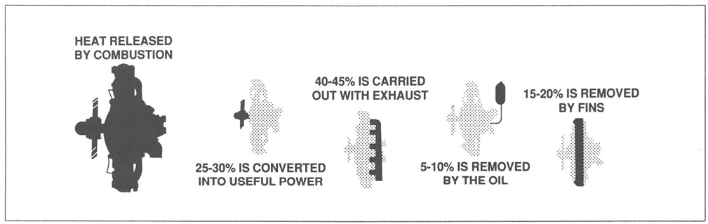
Figure 3-7. Thermal distribution in an engine.
The portion of the total heat of combustion which is turned into mechanical work depends to a great extent upon the compression ratio. Other things being equal, the higher the compression ratio, the larger is the proportion of the heat energy of combustion turned into useful work at the crankshaft. On the other hand, increasing the compression ratio increases the cylinder head temperature and the need for higher octane fuel.
Mechanical Efficiency
Mechanical efficiency is the ratio that shows how much of the power developed by the expanding gases in the cylinder is actually delivered to the output shaft. It is a comparison between the BHP and the IHP. It can be expressed by the formula:
Mechanical efficiency = BHP ÷ IHP
The factor that has the greatest effect on mechanical efficiency is the friction within the engine itself. The friction between moving parts in an engine remains relatively constant throughout an engine’s speed range. Therefore, the mechanical efficiency of an engine will be highest when the engine is running at the RPM at which maximum BHP is developed. Mechanical efficiency of the average aircraft reciprocating engine approaches 90%.
Volumetric Efficiency
Volumetric efficiency, another engine efficiency, is a ratio expressed in terms of percentages. It is a comparison of the volume of fuel/air charge (corrected for temperature and pressure) inducted into the cylinders to the total piston displacement of the engine. Various factors cause departure from a 100% volumetric efficiency.
The pistons of an unsupercharged engine displace the same volume each time they sweep the cylinders from top dead center to bottom dead center. The amount of charge that fills this volume on the intake stroke depends on the existing pressure and temperature of the surrounding atmosphere and how completely the burned gases have been removed from the cylinder during the previous exhaust stroke. Therefore, to find the volumetric efficiency of an engine, standards for atmospheric pressure and temperature had to be established. The U.S. standard atmosphere was established in 1958. It provides the necessary pressure and temperature values to calculate volumetric efficiency.
The standard sea-level temperature is 59 °F or 15 °C. At this temperature the pressure of one atmosphere is 14.69 lbs/sq in., and this pressure will support a column of mercury 29.92 in. high. These standard sea-level conditions determine a standard density, and if the engine draws in avolume of charge of this density exactly equal to its piston displacement, it is said to be operating at 100% volumetric efficiency. An engine drawing in less volume than this has a volumetric efficiency lower than 100%. An engine equipped with a high-speed internal or external blower may have a volumetric efficiency greater than 100%. The equation for volumetric efficiency is:
Volumetric efficiency = Volume of charge (corrected for temperature and pressure) ÷ Piston displacement
Many factors decrease volumetric efficiency; some of these are:
- Part-throttle operation.
- Long intake pipes of small diameter.
- Sharp bends in the induction system.
- Carburetor air temperature too high.
- Cylinder-head temperature too high.
- Incomplete scavenging of exhaust.
- Improper valve timing.
- High density altitude.
Study Questions And Problems
- What three energy forms does the reciprocating engine utilize or convert?
- Describe the operating cycle of the typical aircraft reciprocating engine.
- What percentage of each engine revolution is one cylinder producing power?
- How much horsepower is being used to climb a 3,000 lb airplane at 1,200 fpm at 120 KTS if its total drag is 350 pounds? What kind of horsepower is this?
- How much thrust is the airplane of problem #4 using?
- How much power and thrust is the airplane of problem #4 using if its climb speed is reduced to 100 KTS and drag is reduced to 320 pounds but ROC remains the same at 1,200 fpm?
- What would gauge pressure be in an intake manifold where the MAP is 22" Hg if the airplane is flying at sea level? At 5,000 ft ASL?
- What is BHP? How is it measured?
- On a short-field takeoff, what can the pilot do to reduce FHP and thus increase BHP and THP?