What more ingenious devices than those of M. Trouvé. How not to marvel at them! The knowledgeable inventor showed me an aerial propeller, which could indeed, in its application to aerial navigation, one day lead to the abolition of frontiers and militarism.…
So wrote the great French astronomer Camille Flammarion in Le Voltaire in February 1881. Trouvé’s accidental death in 1902 spared the brilliant electrical engineer the knowledge that twelve years later, aerial navigation would be used to kill and to bomb, assisted by electricity. In 1892, with a war between the USA and Chile threatening, Thomas Edison had expressed different views to the Straits Times of Singapore:
Mr. Edison is very sanguine about his new flying machine; he assures us that it can be projected into space at any given angle and with the aid of an electric motor and revolving fans for about fifty miles, dropping dynamite by the way on the heads of an enemy. The experiments I have made lead me to think that I can carry on this machine 500 lb. of explosive material, and drop it from aloft at any point I choose. Of course, I must allow for the state of the atmosphere, as one does with artillery; but my experiments make me feel that I can come within 20 per cent of my object [emphasis added].1
At the start of World War I, airplanes were only sports machines, powered by V or rotary gasoline engines. Of course, every one of these was fitted with magnetos for starting and the pilot’s legendary command “Contact!” For redundancy, virtually all piston engine aircraft are fitted with two magneto systems, each supplying power to one of two spark plugs in each cylinder. A magneto is an electrical generator that uses permanent magnets to produce periodic pulses of alternating current in airplane engines, in which keeping the ignition independent of the rest of the electrical system ensures that the engine continues running in the event of alternator or battery failure. All the engines for the British Naval and Military Aeroplane Engine Competition in 1914 were using the Bosch ignition system.
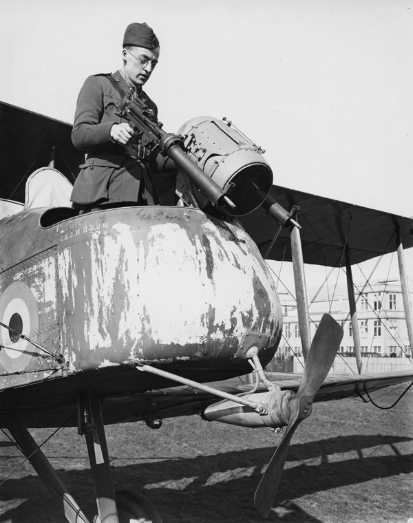
But other than that, pilots went off on reconnaissance, hunting with a cavalry rifle or an automatic pistol. This only lasted for a short time. From December 1914, the first wireless transmitters appeared, which aided aircraft in carrying out some artillery settings. After two years of R&D, Royal Flying Corps Major Herbert Musgrave and his team had devised a system whereby pilots could use wireless telegraphy to help the artillery hit specific targets. The aircraft observer carried a wireless set and a map, and after identifying the position of an enemy target was able to send messages such as A5, B3, etc., to the artillery commander. Unfortunately the early transmitters weighed 75 lb. (34 kg) and filled a seat in the cockpit. This meant that the pilot had to fly the aircraft, navigate, observe the fall of the shells, and transmit the results by Morse code by himself. Also, the wireless in the aircraft could not receive. Originally only a special Wireless Flight attached to No. 4 Squadron RFC had the wireless equipment.
One wireless ace who was prepared to test each new development was Lieutenant B.T. James, who made flight after flight in B.E.2a. James brought the science of wireless in aircraft to a high state of efficiency, testing the Sterling lightweight wireless. By 1915, each corps in the British Expeditionary Force had been assigned an RFC squadron solely for artillery observation and reconnaissance duties. The transmitter filled the cockpit normally used by the observer, and a trailing wire antenna was used which had to be reeled in prior to landing. The Royal Flying Corps began research into how wireless telegraphy could be used to help home-defense aircraft during German bombing raids. In 1916 the RFC developed a lightweight aircraft receiver and a Marconi half-kilowatt ground transmitter. These transmitters were located on aerodromes in raid-threatened areas. The aircraft receiver was tuned in advance, and the pilot had to unreel a 150 ft. aerial from its drum and switch on. Trials started in May, and pilots reported that signals were clearly heard up to ten miles, but at longer distances they weakened.
In April 1915, Captain J.M. Furnival was the first person to hear a voice from the ground when Major Prince said, “If you can hear me now, it will be the first time speech has ever been communicated to an aeroplane in flight.” In June 1915, the world’s first air-to-ground voice transmission took place at Brooklands Motor Course (England) over about 20 mi (32 km). Ground-to-air was initially by Morse, but it is believed 2-way voice communications were being achieved by July 1915. In early 1916, the Marconi Company (England) started production of air-to-ground radio transmitters/receivers which were used in the war over France. By November 1918 the newly established RAF had some 600 aircraft fitted with the new Mark III choke-controlled telephone set, operating in conjunction with 1,000 ground stations and manned by over 18,000 wireless operators.
Over in the USA, in 1917 AT&T invented the first American air-to-ground radio transmitter. They tested this device at Langley Field in Virginia and found it was a viable technology. In May 1917, General George Squire of the U.S. Army Signal Corps contacted AT&T to develop an air-to-ground radio with a range of 2,000 yards (1800 m). By July 4 of that same year, AT&T technicians achieved two-way communication between pilots and ground personnel. This allowed ground personnel to communicate directly with pilots using their voice instead of Morse code. Though few of these devices saw service in the war, they proved this was a viable and valuable technology worthy of refinement and advancement; therefore, further models had this technology installed into biplanes on airstrips in France by 1919.
Airships also benefited. In 1917, Rigid No. 9 was fitted with a valve transmitter at Howden, the first such radio installation in a rigid airship; earlier spark sets were thought to be too dangerous because of the stored inflammable hydrogen. Subsequently all British dirigibles carried Marconi valve sets, and in late 1917, RFC long-range night bombers were also fitted with Marconi equipment. For the electrical power required to transmit, the British Coastal class blimps, one of several types of airship operated by the Royal Navy, carried a 1.75 horsepower (1.30 kW) ABC (Anglo-Belgian Corporation) auxiliary gas engine. These powered a generator for the craft’s radio transmitter and, in an emergency, could power an auxiliary air blower.
Parallel development had been taking place for nocturnal flight. Initial nighttime test flights with particular lighting, by causing the loss of several crews, brutally demonstrated that an aircraft cannot count on the light alone to land. The question was abandoned for almost one year. In 1914 No. 1 Squadron, Royal Naval Air Service fitted an 80hp Avro 504 with a 50-watt searchlight mounted in the undercarriage structure. This was powered by a 12-volt battery mounted in the fuselage. By 1915 the RNAS fitted a Royal Aircraft Factory BE2c with instrument panel lighting which had variable intensity. The aircraft was also fitted with two 5⅜ inch (13 cm) headlamps, one on each outer interplane strut and set to converge on the ground 30 yards (27 m) ahead of the aircraft. The installation only weighed 16 pounds (7 kg). The Royal Naval Air Service at Burgh Castle fitted a Lucas headlamp to an aircraft which proved “very useful.”2
The British RFC Supermarine Nighthawk, an anti–Zeppelin night fighter, used a trainable nose-mounted searchlight, a 1½-pounder (37 mm) Davis gun mounted above the top wing with 20 shells, and two .303 in (7.7 mm) Lewis guns. Power for the searchlight was provided by an independent gasoline engine–driven generator set made by ABC Motors, possibly the first instance of a recognizable airborne auxiliary power unit hybrid. Although touted as being able to reach 75 mph (121 km/h), the P.B.31E prototype only managed 60 mph (97 km/h) at 6,500 ft (1,981 m) and took an hour to climb to 10,000 ft (3,048 m), which was totally inadequate for intercepting Zeppelins.
When at the end of 1915, daytime flying becoming dangerous for the heavy and clumsy bomber planes, these were oriented towards night flights. They were equipped with lightweight lighting installations, with small 300W generators constant tension–activated by a wooden reel and supplying energy to a ramp of three small adjustable parabolic lamps placed at the front of the airplane. These summary installations, just like those of the wireless transmission, underwent successive improvements (back-up batteries, more powerful lamps, supple warming clothing, etc.)
1915: The only disadvantage when you lit up your bombing target from above was that you were a “sitting duck” for enemy ground fire. The wind-powered turbine gave electrical power to the searchlight (©RAF Museum).
So electricity became part of the way of life of the military pilots. In France, special services were created at the S.T. Aé to the S.F. Aé; squadrons and aerodromes were equipped with electricians specially recruited and trained in a school perfectly organized at the Retrenches Park of Paris. Entirely new equipment was put into service. Military telegraphy brought out a series of transmitters and receivers specially developed for the applications to which they were aimed. The Technical Section of the Aéronautique researched and developed landing lights, searchlights of optical telegraphy, various body warmers, and a whole range of equipment for generating and distributing electricity. Aircraft that benefited from these developments were the Farman F-50 night bomber, Spad fighter plane, Nieuport, Breguet and Salmson.
Combat pilots flying at night, in order to see their dashboard, had small, shielded incandescent lamps placed next to the dials. Importantly, these lamps could be turned on and off as needed. However, engine vibrations often caused light bulbs or electrical connections to fail. Even the small amount of light emitted by such lamps could cause great difficulty for a novice since it could be too dazzling; later, luminous paint composed of zinc sulfide and radium was applied to the dials.3
There was, however, one flying machine that went further than using electricity for heating and lighting. Its innovator was a forty-year-old Austro-Hungarian pilot officer called Stephan von Petróczy. A graduate of the Theresian Military Academy in Wiener Neustadt, Petróczy trained to fly in 1910, obtaining Pilot Diploma No. 13, despite crashing on a flight from Wiener Neustadt to Fischamend, suffering a broken arm. He became a flying instructor at Wiener Neustadt, the first flying school in the Empire. On the outbreak of World War I, he flew combat planes first on the Serbian front and then the Russian front. But in 1915 he was withdrawn from service to establish a flight training battalion to compensate for the high pilot fatalities, and then promoted to Commander of the Aviation Arsenal. Well aware, from his own experiences, that the hydrogen-filled observation balloons were too clumsy and dangerously inflammable, Petróczy conceived of a tethered device, deriving its energy from the land. For his project, in April 1916, the Imperial War Ministry allotted Petróczy 100,000 crowns to conduct experiments on a prototype. In this he was assisted by two fellow Hungarians: an aerodynamics expert, Lieutenant Dr. Theodore von Kármán; and engineer Wilhelm Zurovec, who built a 6 hp Austro-Daimler electric-generating motor at 2400 rpm, weighing 4 kg (9 lbs.) which could power a 35 kg (77 lbs.) flyable model.4
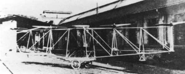
This very rare 1918 photograph shows the PKZ 1 (Petróczy-Kármán-Zurovec), the world’s first tethered quadcopter, deriving its electric power from an Austro-Daimler gasoline engine. Designed for use as an aerial observation machine, the prototype was abandoned after the 1918 Armistice (courtesy Reinhard Keimel).
The full-scale PKZ1 rotorcraft was built by Mátyásföld. A 190hp Austro-Daimler-generated electric motor was used to drive two propellers in front of the observer and two behind, as in today’s quadcopter. The electrical power was transmitted through a cable but still the motor weighed 195 kg. In flight, the power would be transmitted through an 800-m-long aluminum cable. On its first test flight in Fischamend Hangar, the unit took off at a rotor speed of 700 rpm and rose up to the height limit of 5 meters (16 ft.). Approximately fifty flights took place between July 1917 and March 1918, with heights of more than 10 m (33 ft.) obtained. A second PKZ was built and tested to an altitude of 50 meters (164 ft.), but then, in a demonstration flight on June 10, 1918, in Fischamend, in front of a high-level military delegation, the machine crashed. Five months later, Armistice was declared and the project abandoned. But at least the potential of an electrically-powered quadcopter had been demonstrated. In the years which followed, Stephan von Petróczy was involved in the construction of the Hungarian Air Force—gasoline-engined, of course.
While the PKZ aircraft were being test flown, in May 1917, an article titled “Electrifying the Aeroplane” appeared in The Electrical Experimenter describing some recent advances. It begins: “Electricity is being rapidly introduced in the new art of Aeronautics.” The article refers to “the aerial limousine the Autoplane, recently exhibited at the Aeroplane Show in New York.” The Autoplane had just been invented by Glenn Curtiss of Seattle as a roadable aircraft. It was a triplane, using the wings from a Curtiss Model L trainer, with a small foreplane mounted on the aircraft’s nose. Its aluminum body resembled a Model T and had three seats in an enclosed cabin, with the pilot/chauffeur sitting in the front seat and the two passengers side-by-side to the rear. It used a four-blade pusher propeller and a twin-boom tail. An electric start 100 horsepower (75 kW) Curtiss OXX engine drove the propeller via shaft and belts. It was shown at the Pan-American Aeronautic Exposition at New York in February 1917. Although the vehicle was capable of lifting off the ground, it never achieved its projected 65 mph (104 kph) in full flight. The entry of the United States into World War I in April 1917 ended development of the Autoplane. Electrically, at least it had electric heating and cabin lighting.
The Electrical Experimenter article continues with devices innovated by Elmer Sperry, then working with Peter Hewitt on an Automatic Airplane (see Chapter Nine). An adapted Curtiss N-9 Seaplane, which included the Sperry automatic gyroscope, serves to control and maintain an airplane in any desired position and also free a pilot for aiming and dropping bombs. The article also mentioned an Incidence Indicator,
which warns the aviator before he stalls and enables him to get the best climbing and gliding angles out of his machine mounted on a forward strut. The lamp bank and indicator is on the instrument cowl, always visible to the pilot observing other essential instruments. The red light warns the aviator before he stalls as well as when he begins climbing at a dangerous angle. The white lamp signals wherever the pilot dives at too steep an angle. The green light indicates the best climbing angle. Being of low voltage as well as low current consumption, the lights can be operated by a dry battery, encased in metal and installed wherever most convenient. The signals are regulated by a vane operated by the air stream.
To provide the electrical power necessary to gyroscopically motor-control his airplane, Sperry also invented an aerodynamically-shaped wind-driven generator, mounted on the upper wing in the slipstream of the airplane’s propeller. In his patent, filed in December 1916, Sperry stated:
As has become the case with automobiles, electricity has been found to be an indispensable asset for aeroplanes also. It is being used for lighting signals and other lights, operating wireless transmission sets, operating the aeroplane controls through servo-motors, actuating various kinds of instruments for signaling to other machines or between the pilot and observer, operating gyroscopes or other stabilizing apparatus, and for charging engine starting batteries. The object of this invention is to provide a practicable means whereby a sure supply of electricity at a constant voltage may be obtained.
Unknown to Sperry, in January 1915, Bruno Rosenbaum of Berlin had filed a similar patent for propeller-driving wireless sending equipment on aircraft, and particularly referred to the case where the propeller was driven by the air current generated by the main propeller and not by the air current created by the flight of the aeroplane. When this arrangement was adopted, it would be possible to drive the generator of the sending equipment when the craft is not in flight, as the main propeller may be kept in motion in order to drive the smaller propeller. With Armistice, Rosenbaum would sell his invention to Westinghouse.
By this time, airship bombing raids were terrifying city dwellers. Japan was on the side of the Entente Powers, and although their air force was nonexistent, in October 1916 Toshio Yoshida of Tokyo, “subject of the Emperor of Japan,” applied for a patent for “a novel system for dropping a bomb or bombs or the like from an airplane or airship.” This was “a telescopic aiming device using electrical circuit including electromagnets for operating the said electrically controlled means to release the bomb from the case when the airplane or airship reaches a proper point above an object to be attacked.” (U.S. 1290858 was granted in 1919.) Count Oscar Wilcke, who had served as a Zeppelin airship pilot based in Friedrichshafen, Germany, carrying out those notorious raids on the British Isles, also obtained an almost identical patent for an electromagnet-powered bomb-throwing apparatus, including a device for testing the electric circuits. Wilcke had applied for this patent in 1916 at the height of the Zeppelin raids, and ironically obtained it in March 1921 (Patent No. 316584) after Germany had been defeated and all combat Zeppelins had been destroyed.
In 1917, Godfrey L. Cabot, a middle-aged American industrialist and airplane pilot and organizer of the Naval Militia Aviation Unit based in Marblehead, invented and patented:
An apparatus for launching aircraft such as airplanes and hydroaeroplanes, the principal object being to provide electro-magnetic means for holding the aircraft upon the launching apparatus until the required speed has been attained, and for then releasing it. A further object is to provide electric means for operating the launching apparatus and means for simultaneously cutting off the current from said operating means and the electro-magnetic holding means when the ship is traveling at a safe speed for flight. Yet another object is to provide a track for the catapult carriage upon which said carriage and aircraft move forward under the power of the latter or of both for a predetermined distance, the electric propelling means of the carriage and the electric magnet being then automatically thrown into action so that the craft is gradually driven faster until a safe flying speed is attained.
Cabot filed his patent in 1917 and obtained it the following year. In June 1918, Bernhard E. Fernow, Jr., engineer for the Cutler-Hammer Manufacturing Co. of Milwaukee, obtained U.S. Patent 1410395 A for “a system of electro-magnetic brakes to stop airplanes.”
Throughout the war, pilots had been able to fire their machine guns through their spinning propellers without splintering them, thanks to a mechanically or hydraulically synchronized timing system. By the end of the war, German engineers were well on the way to perfecting a gear using an electrical link between the engine and the gun, with the latter being triggered by a solenoid. When the guns entered a forbidden zone, electrical power was cut off to disable the trigger.
Following the Armistice, a number of bomber planes had the space previously taken up by bombs replaced with luxurious cabins which had to be heated and lit for passenger comfort. The other challenge was navigation and various approaches were used, all indirectly dependent on electricity. The April 1922 issue of Aerial Age Weekly reported the first nighttime flight from the UK to the Continental Air Route. A British Air Ministry airplane took off from Croydon Airport, London, at 9:20 p.m., landed at an aerodrome at St. Inglevert, France, and returned to Croydon at 11:30 p.m. On board were a couple of Air Ministry personnel who handled RDF wireless communication and lighting, as well as the crew of the plane itself. No passengers were on board.
Unable to use the same lighthouses for ships as for navigation, the French also decided to build lighthouses that airliner navigators could see at great distances. To stake out the Paris-Algiers air route, an electrically powered lighthouse was commissioned by the Technical Section of the Aéronautique at Issy-les-Moulineaux and built by the firm of Barbier, Bénard & Turenne. It had an intense luminosity of one thousand candles and was composed of 8 two-meter diameter lenses extending 180°; in the foyer of each one was an arc lamp absorbing 120 amps at 65 volts. Each lens in its optical system was made up of seventeen dioptric elements and catadioptric elements.
In 1925, the 11-meter (36 ft.) lighthouse was dismantled and transported for erecting on Mont Afrique, twelve kilometers from Dijon. It was inaugurated that summer by Gaston Gerard, mayor of Dijon, and General Jacques Theodore Saconney. Run and maintained by the Aerial Navigation Service, this was the first of over thirty terrestrial aeronautical lighthouses for aircraft, at a time when air navigation was still carried out by eyesight. Located at the crossroads of Paris-Switzerland-Italy and Paris-Mediterranean, the powerful beam of this aeronautical beacon was visible in certain conditions up to 400 km (250 mi). It is even said that it was “visible” from Rouen, Brussels, Antwerp and Turin.5
The same happened across the USA. After initial tests with simple bonfires, in 1922 two young U.S. Army Air Corps lieutenants, Donald L. Bruner of Iowa and Harold R. Harris of Illinois, based at McCook Field, Dayton, Ohio, proposed ideas for electrically lit airport boundaries, spot-lit windsocks, and rotating beacons on towers. Each beacon consisted of a revolving motor-driven light that sat at the top of a 60-foot (18 m) tower. At night, the beacon flashed in a certain sequence so that pilots could match their location to the printed guide that they carried in their aircraft. The first nighttime flight test was between Dayton and Norton Field in Columbus, a distance of 72 miles (116 km). Its financing had been thanks to Paul Henderson, Second Assistant Postmaster General, who had managed to secure funds for lighting a portion of the transcontinental, despite initial criticism. By 1926, all segments were in place; the Transcontinental Airway System’s light beacons were brought under the authority of the Bureau of Lighthouses, and crossing the country by air (day or night) was considered much safer. In 1926 Bruner, promoted to captain, received the Distinguished Flying Cross for developing and perfecting night-flying equipment, thus making it possible for military and commercial airplanes to traverse the length and breadth of the United States during the hours of darkness. He went on to invent and patent airplane landing lights (U.S. 1554198), electrically warmed anti-frosting/fogging goggles (U.S. 2099464), and electrically retractable landing lights (U.S. 2124050). By this time there were about 1,550 electric light beacons stretching across 18,000 miles (30,000 km) of the USA.
In 1921, Nikola Tesla submitted his first patent: “An apparatus for Aerial Transportation,” modifying it in an application made in October 1927, which was granted in 1928 (U.S. 1,655,114). In this, he described a “helicopter-plane” adapted for vertical and horizontal propulsion and change from one to the other attitude, the combination of means for tilting the machine in the air, a fluid pressure generator of a capacity several times greater than normally required in horizontal flight, a motor capable of carrying overloads adequate for support in all attitudes, and means for controlling the supply of the fluid to the motor in accordance with the inclination of the machine.
Far from these practical applications, in India, a mystic called Subbaraya Shastry was writing a book called Vaimãnika Shastra, or The Science of Aeronautics. He is said to have obtained the information by psychic channeling with the ancient Saint Bharadvaja. The story goes that Subbaraya Shastry was believed to have contracted leprosy. He left his home and spent nine years living in the forest. During this time he is supposed to have spoken with the ancient saint (sage Bharadvaja) and was enlightened with this newfound knowledge of flying machines. He later returned home (as he also had been cured of leprosy), but Shastry could not read or write, so he dictated his new knowledge over the period of 5 years (25 years after the psychic experience itself). The dictated text was apparently discovered in 1952 by G.R. Josyer, who later translated it into English in 1973. This publication contains eight chapters claiming that ancient vimãnas from the King Ravana legend were actually feasible flying machines, perhaps even similar in ability to rockets. The text indicates that propulsion was provided using rotating gyroscopes of electricity and mercury.6
Some visionaries were more practical. In 1929, Hermann Julius Oberth, an Austro-Hungarian-born German physicist and engineer, wrote a book, Wege zür Raumschiffahrt (Ways to Spaceflight). In this, he devotes a whole chapter, “Das elektrische Raumschiff” (“The Electric Spaceship”), to electric propulsion, advocating electrostatic acceleration of electrically charged gases that can be created from refuse on the orbiting space station that is a major theme of his book.7 But not of this one.
On a more practical level, to deal with the problems of flying through thick fog or poor visibility, on April 3, 1928, French Captains Gérardot, Cornillon, Vigroux and Rey—respectively, pilot, navigator, mechanic and assistant pilot—took off in their Lorraine-engined Amiot from Le Bourget near Paris, to carry out a 68-hour, 10,000 km (6,000 mi) study flight across Africa, where they navigated by “radiogoniométrie électromagnetique” or radio direction finding. The flight path took in Colomb-Bechar, Timbuktu, Bamako, Dakar, and Casablanca, returning then to Villacoublay. During the flight, Cornillon was only able to use his wireless positioning until Oran, where, due to its malfunctioning, he had to resort to a traditional compass.
Such Marconi wireless direction-finding was also used by those in airships or solo airplanes risking their lives to make transatlantic or polar flights to transmit their whereabouts either to potential rescuers or to the press.
On September 24, 1929, Lieutenant James H. Doolittle, U.S. Army Air Corps, Ph.D. MIT, made the first completely blind airplane takeoff flight and landing, solely by reference to instruments on board his aircraft. Flying from the rear cockpit of a civil-registered two-place Consolidated NY-2 Husky training airplane, NX7918, Doolittle had his visual reference to earth and sky completely cut off by a hood enclosure over his cockpit. The experimental gyroscopic compass, artificial horizon and a precision altimeter were developed by Elmer Sperry, Jr., and Paul Kollsman, both of Long Island, New York. Funding for the Full Flight Laboratory at Mitchel Field was provided by the Daniel Guggenheim Fund for the Promotion of Aeronautics.
To train new pilots, in 1929 J.P. Buckley patented an aeronautical instructing device (or flight simulator) “comprising a body, means of mounting said body for universal movement, electric energizers for imparting movement to said body, circuits for said energizers, means for closing circuits for selected energizers operable by an occupant of the body.”8
Since the beginnings of aviation, no device had been installed on airplanes that would indicate when one or both of the wheels had either been broken off in ascending or fallen off after a plane was in the air. Numerous accidents had occurred due to the pilot’s ignorance of such a condition, because of his inability to see the landing gear. In 1930, Harry H. Semmes of the Bendix Aviation Corporation, South Bend, Indiana, applied for a patent for an electrical circuit and a mechanical device in or on the airplane for indicating when a wheel of an airplane has broken loose and fallen from its axle. (Patent U.S. 2025909 was published in 1935.)
In the same way, the hazards of flying caused by ice accumulating on airplane wings and stabilizers at high altitudes or in cold weather were well known, the additional load of the ice on the plane often seriously interfering with safety. Again in 1930, Archie F. Thompson of the Iceless Air Wing Corporation, Tulsa, Oklahoma, applied for a patent concerning a heater for airplane wings. In combination with aircraft including a source of electrical energy, heating wires were arranged on a selected wing surface, a layer of insulation between said surface and wires, feed wires leading from the source of energy to the heating wires, means interposed in the feed wires for controlling the amount of current flowing through those wires, and a covering for the insulation and heating wires substantially conforming in shape to the wing surface and spaced therefrom to form a dead air chamber. Thompson was granted Patent U.S. 1868468A in 1932, but the Wall Street crash had bankrupted him.
Electricity continued to power testing devices. In 1935 a 24-ft (7 m) wind tunnel, powered by a 2,000 hp DC electric motor, opened at the Royal Aircraft Establishment, Farnborough, England. Parallel to this a seaplane tank was commissioned and consisted of a 400-yard (366 m) tank with rails either side on the edges of the tank. The rails supported a trolley that ran above the tank carrying a model under test. The model was in contact with the water surface and the forces generated could be measured. The trolley was propelled by electric motors and the control gear was similar to that found in tram cars. A brake was applied automatically towards the end of each run.9
One piece of electrical apparatus regularly used on board aircraft during the interwar years was the Eagle Automatic Electric Aircraft Camera, developed by Colin M. Williamson of Willesden Green, London, and used throughout the world for air survey photography in all types of aircraft. In 1928, the RAF developed an electric heating system for the aerial camera. This allowed reconnaissance aircraft to take pictures from very high altitudes without the camera parts freezing.10
In 1932, similar to Hiram Maxim’s fairground ride of thirty years before, brothers Victor and Joseph Stanzel of Schulenburg, Texas, developed a fairground ride called “Fly-A-Plane.” They designed and built a full-sized two-passenger conventional high-wing cabin-type electric airplane on a supporting beam structure, able to carry up to four passengers at a time. When it was completed in 1932, they stationed it along a well-traveled road near town and offered rides for twenty-five cents. Joe served as pilot of the aircraft. Later, it was located in a Houston park and eventually sold to an amusement park in Kilgore, Texas. Victor Stanzel received his first patent for the “Fly-A-Plane Amusement Ride” in December of 1933 (U.S. 1941024 A).
During the 1930s a prevailing movement in the design of buildings and furniture was Art Deco, which extended from a cigarette case to the Chrysler Building in New York City. Art Deco pieces included electric desk lamps and ceiling fans in the form of airplanes made of Bakelite or chromed metal. Obviously switching on the light or the fan would not make the airplane fly!
In 1941 Arthur M. Young, an American inventor, designed Bell Aircraft Corporation’s first helicopter, the Model 30, and innovated the stabilizer bar used on many of Bell’s early helicopter designs. Although these were gasoline-powered, Young later recalled, “As a boy, in about 1915, I made a crane from ‘Meccano Set’ parts which would lift one of my little brothers into the air with the help of a motor and endless pulley. I also made the electric motor. That was my initiation into the electrical field.” In 1927, as a Princeton University graduate, Young started work on model helicopters and used electric hover motors to drive the rotor head. By 1939, he decided to abandon larger scale models and the tip powered concept and concentrate on smaller models which were again powered by electric vacuum cleaner motors.11
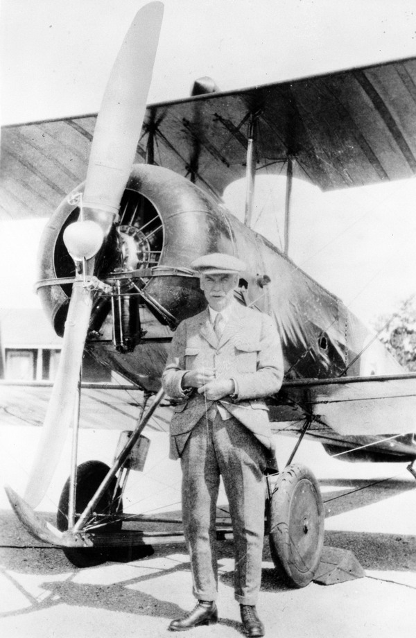
In 1929, Rupert Turnbull stands beside his invention, the electrically powered variable pitch propeller, which improved takeoff and extended the range of many gas airplanes (Canada Aviation and Space Museum).
If electricity could not be the main propulsion unit, might it at least be used to control propeller pitch? So reasoned a Canadian engineer, Wallace Rupert Turnbull. Coming from a wealthy family, Turnbull studied at Cornell University and in Germany until age 25, and then worked at the Edison Lamp Works, Harrison, New Jersey, for six years, learning about electricity. He then developed an electrically activated variable-pitch propeller that gave aircraft maximum power in takeoffs and landings, and economical cruising at speed. He built the first wind tunnel in Canada to test propeller designs under a constant wind speed. This was tested with an Avro 504K airplane on June 29, 1927, at Camp Borden, Ontario, Canada, then patented in 1929 (U.S. Patent 1,828,348).
That same year, Turnbull won a silver medal at the Inventions Show in New York City, then sold his patent to the Reed Propeller Company, a subsidiary of the Curtiss Airplane and Motor Company, a division of Curtiss-Wright Ltd., Montreal. While Turnbull went on to other inventions, his electrical propeller was further refined by Charles W. Chillson.
Chillson had received his B.S. in mechanical engineering from Stanford University in 1931 and gone on to work in chemical engineering at the California Institute of Technology (1931–36). At the same time, Chillson worked with C.K. Greene on a mechanical controllable-pitch propeller, which progressed through whirl-testing at the USAAF Engineering Division at Wright Field, Ohio. He then moved to the Curtiss-Wright Propeller Division as their engineer and project designer to concentrate on the electrical propeller. His patent (Serial No. 261,879), filed March 15, 1939, explains how the fluid pressure controlled by the governor actuates an electric switch, which in turn controls the operation of an electric motor to adjust the pitch of the propeller blades.
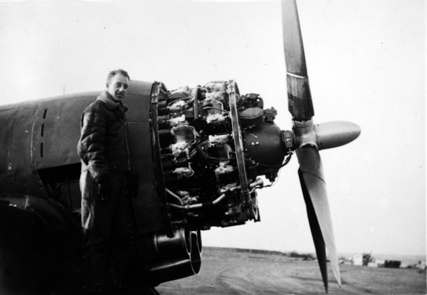
By 1940, the electric propeller had become more sophisticated. During World War II, Curtiss-Wright manufactured 146,468 electric propellers with variations, while the German Luftwaffe’s Messerschmitt BF 109F was also equipped with the system (San Diego Air & Space Museum).
During World War II, Curtiss-Wright manufactured 29,269 airplanes, 142,840 aircraft engines, and 146,468 electric propellers with variations ingeniously developed by Chillson and his team. Between 1942 and 1945, the Curtiss-Wright propeller factory in Beaver, Pennsylvania, fabricated more than 100,000 new propeller blades for a variety of aircraft, such as the Lockheed YP-38 1940 twin engine bomber. Rotol Airscrews in the UK purchased a manufacturing license to produce the Curtiss Electric propeller at their Kilmarnock plant.
The German Luftwaffe was swift to adapt the electrical pitch propeller design to their warbirds. With a license originally obtained from Curtiss, the VDM (Vereingite Deutsche Metallwerke) electric propeller pitch control mechanism was fitted to the Messerschmitt BF 109F. Propeller pitch was changed electrically, and was regulated by a constant-speed unit, though a manual override was still provided. Designed by Kurt Tank, the Focke-Wulf Fw 190 Würger (English: Shrike) single-seat fighter aircraft, dubbed the “Butcher Bird,” used an electric VDM control-pitch propeller. In addition, to minimize changes in the aircraft’s trim at varying speeds, thus reducing the pilot’s workload, the entire horizontal tailplane was tilted with an electric motor, with an angle of incidence ranging from -3° to +5°. The retractable undercarriage was operated by pushbuttons controlling electric motors in the wings, and was kept in position by electric up and down-locks. The armament was also loaded and fired electrically. The Fw 190 F-8/U4, created as a night fighter, was equipped with various electrical systems such as the FuG 101 radio altimeter, the PKS 12 automatic pilot, and the TSA 2 A sighting system.12
The increasing sophistication of warplanes meant that ground facilities also became more sophisticated. The high-powered engines in use could no longer be started by hand-swinging the propeller, but powered starting systems had to be provided. One of these, the Trolley Accumulator, was used for aircraft such as the Spitfire, which had an inbuilt electric starter motor. “Trolley accs” were produced in several forms, but they all had a bank of lead/acid batteries contained in a covered box, which had been wired “in series” so that each lead/acid cell (nominally producing about 2 volts) produced 12 volts and sufficient power to turn over the standard aircraft engines of the day. When not in use, these accumulators were connected to the main electricity supply at the RAF station they were on, to build up charge (usually overnight); they would need periodic servicing and topping up with distilled water, as they tended to lose that component of the electrolyte during the charge/discharge process.13
To move around the giant plants where these warplanes were being built was always a challenge. In September 1935, Consolidated Aircraft Corporation opened its new “Building 1,” a 247,000-square-foot (22,900 m2) continuous flow factory in San Diego, California, while Douglas Aircraft Company’s largest facility was its Long Beach plant, totaling 1,422,350 sq. ft. How executives and technicians might get around these hangars silently and safely was solved by Consolidated’s chief test pilot, William B. Wheatley. Bill Wheatley was as much an innovator as a pilot, having patented “Apparatus for arresting launching devices for airplanes”; “Launching airplanes from water” (flying boats); “Device for handling aircraft”; etc. His solution to mobility was the “Electricycle,” a standard bicycle with the battery and single-speed electric motor mounted on the front fork. Wheatley’s Electricycle was as streamlined as the airplanes he was test-flying, with production advantages secured through utilization of standard parts, foot-controlled throttle and brakes, and easy-to-exchange batteries. For manufacture, in April 1941, Wheatley joined forces with Newton C. Blood and O.L. Weaver of Blood Sales Co., Inc., with their plant in Long Beach, California. At the time, Consolidated was developing the XB-24 Pratt and Whitney–engined bomber. In June of 1941, Wheatley and his crew of four were killed undertaking the final test of the B-24 before the aircraft were to be delivered to the Royal Air Force in England. The crash into San Diego Bay was initially thought to be sabotage, but was later discovered to have been caused by a mechanical anomaly in which the elevator locked in the “up” position, rendering the crash unavoidable. While more than 18,000 B-24 Liberators were built in just over five years, making it the largest military production in U.S. history, nothing else was heard of the Electricycle.
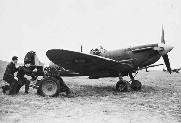
In the later stages of the war, high-powered engines in use could no longer be started by hand-swinging the propeller, so powered starting systems had to be provided. One of these, the Trolley Accumulator, was used for aircraft such as the Spitfire and the Hurricane (©RAF Museum).
The Avro Lancaster was a British four-engined Second World War heavy bomber designed and built by Avro for the Royal Air Force (RAF). The “Lanc,” as it was affectionately known, thus became one of the more famous and most successful of the Second World War night bombers, delivering 608,612 long tons of bombs in 156,000 sorties. But with its rear gun turret, neither the mid-upper nor the rear gunner’s position was heated, and the gunners had to wear electrically heated suits to prevent hypothermia and frostbite. Extremely low temperatures would occur above 10,000 ft. (3,000 m).
In September 1944, the first of thousands of B-29 Superfortress bombers rolled out of Boeing’s assembly line in Wichita, Kansas. Based on the highly successful platform of the B-17 bomber, the B-29 became the largest aircraft operational during World War II, a combination of cutting-edge tech and devastating firepower. This was due to a battery of .50 Browning M2 machines linked to five interconnected analog computers, built at General Electric’s Erie plant. These were located in the nose and tail positions and three Plexiglas blisters in the central fuselage, and required only one single gunner and a fire-control officer. This electrical system increased the weapons’ accuracy by compensating for factors such as airspeed, lead, gravity, temperature and humidity.
Simpler, the ball turret, an electrically activated, spherical-shaped, altazimuth mount gun turret, was fitted to some American-built aircraft such as the Boeing-17E Flying Fortress, the B-24H Liberator, and the United States Navy’s Liberator, the PB4Y-1. It was manufactured by Sperry, and to a lesser extent Emerson Electric.
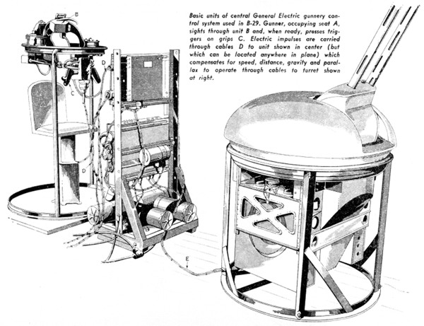
1944: The USAF’s B29 Superfortress bombers were equipped with an electrically activated, spherical-shaped, altazimuth mount gun turret, giving gunners a lethally precise firepower (author’s collection).
Second World War aircraft needed large amounts of power, as they had many electrical systems and literally miles of wiring—a Wellington bomber had approximately 7 miles (11 km) of wiring, and the Halifax had no less than 12 (20)!
While the air war was going on, in 1943, some engineers still believed in electricity. Stanley Bizjak, a 31-year-old inventor living in the tiny village of Crivitz in Marinette County, Wisconsin, obtained a patent on
an electrically powered glider, partially supported by buoyant gas, which could take off silently and operate under its own power during flight, and one which during aerial maneuvering can have its motive power manually disconnected so as to utilize the glider’s propeller which is always directly connected to a generator to automatically regenerate the power batteries independently of the electrical power to compensate for loss of electrical energy consumed in rising into the air or else for power expended in flight in performing various aerial maneuvers which the electric motor per se is incapable of producing.
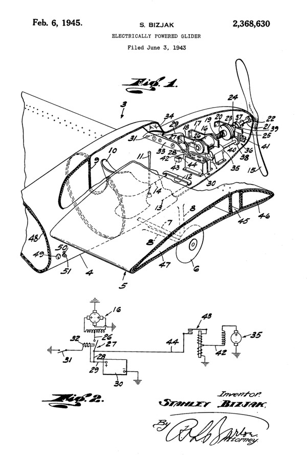
In 1945, U.S. Army Corporal Stanley Bizjak, based at his family dairy farm in Crivitz, Wisconsin, received U.S. Pat. No. 2,368,639 for this electrically powered glider. He too had filed in June 1943, four months after Westinghouse.
Bizjak had also patented a tractor embodying a retractable mechanism whereby it could be propelled alone on four wheels, or could be propelled on two wheels when hitched to a plow, harrow or other soil-working implements. We do not know whether the Bizjak electric glider, for which he obtained U.S. Pat. No. 2,368,639 in 1945, was built.
A unique aircraft produced by the Luftwaffe, designed by Alexander Lippisch, was the rocket-powered Messerschmitt Me163 “Komet.” In early July 1944, piloted by Heini Dittmar, the Komet reached 1,130 km/h (700 mph), an unofficial flight airspeed record unmatched by turbojet-powered aircraft for almost a decade. Less known is the fact that a small windmill generator on the extreme nose of the fuselage, and the backup lead-acid battery inside the fuselage that it charged, provided the electrical power for the radio, the Revi1 6B, -C, or -D reflector gunsight, the direction finder, the compass, the firing circuits of the cannons, and some of the lighting in the cockpit instrumentation. This was later developed as the Ram Air Turbine (RAT), a propeller-driven generator which is moved into the airflow when all other means of generating electricity and hydraulic power have failed. With the exception of crop dusters, modern aircraft use RATs only in an emergency.
It is also reported that towards the end of the war, the Nazis were testing an electric airplane developed by an Austrian, Viktor Schauberger. In 1940, Schauberger had begun construction of his Repulsin(e) discoid motor in Vienna with help of the Kertl Company. He patented his idea on March 4, 1940, in Austria under Patent 146,141. But very soon afterwards he was reported by the Viennese Association of Engineers to the SS, who placed Schauberger in a mental hospital in Mauer-Ohling. Schauberger was then forced to work with Messerschmitt on liquid vortex cooling systems, and with Heinkel concerning applications of water towards aircraft engines. At this point Heinkel received reports on the early Repulsin A. It was at the Mauthausen Concentration Camp in Upper Austria, under orders from Heinrich Himmler himself, that Schauberger was to carry out research and development for the Third Reich war effort. He was given approximately 20 or 30 prisoner engineers to proceed with his research into what was termed “higher atomic energies.” For this Schauberger was given special dispensations from the SS for both himself and fellow engineers.
The construction and perfection of the Repulsin A model discoid motor continued until one of the early test models was ready for a laboratory test that ended in disaster. The model was 2.4 meters in diameter with a small high-speed electric motor. Upon initial start-up the Repulsin A was set in motion violently and rose vertically, quickly hitting the ceiling of the laboratory, shattering to pieces. The SS were not pleased and even threatened Schauberger’s life, suspecting deliberate sabotage. Despite this, according to Schauberger, a full-sized “flying saucer” was built in collaboration with the first-class stress-analyst and propulsion engineers assigned to the Austrian. It was apparently flight-tested on February 19, 1945, near Prague, when it attained a height of 15,000 meters (45,000 ft.) in 3 minutes and a horizontal speed of 2,200 km/hour (1,366 mph)! It was destroyed by the Nazis before it could be captured by the Allies. We do not know whether it too used an electric motor.14