Properties of molecules depend not only on the bonding of atoms but also on the molecular geometry—the three-dimensional arrangement of the molecule’s atoms in space. The chemical formula reveals little information about a molecule’s geometry. Only after performing many tests designed to reveal the shapes of the various molecules have chemists developed successful theories to explain certain aspects of their findings. One theory structurally accounts for molecular bond angles. The other is used to describe changes in the orbitals that contain the valence electrons of a molecule’s atoms. The structural theory that deals with the bond angles is called the VSEPR theory, whereas the one that describes changes in the orbitals that contain the valence electrons is called the hybridization theory. (VSEPR represents Valence Shell Electron Pair Repulsion.)
Two theories explain molecular structure. VSEPR theory uses valence shell electron pair repulsion. Hybridization theory uses changes in the orbitals of the valence electrons.
VSEPR uses as its basis the fact that like charges will orient themselves in such a way as to diminish the electrostatic repulsion between them.
These basic arrangements are important to learn!
Configurations often appear as questions on the SAT test.
Ammonia (NH3) and water (H2O) are examples of molecules in which the central atom has both shared and unshared electron pairs. Here is how the VSEPR theory accounts for the geometries of these molecules.
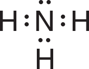
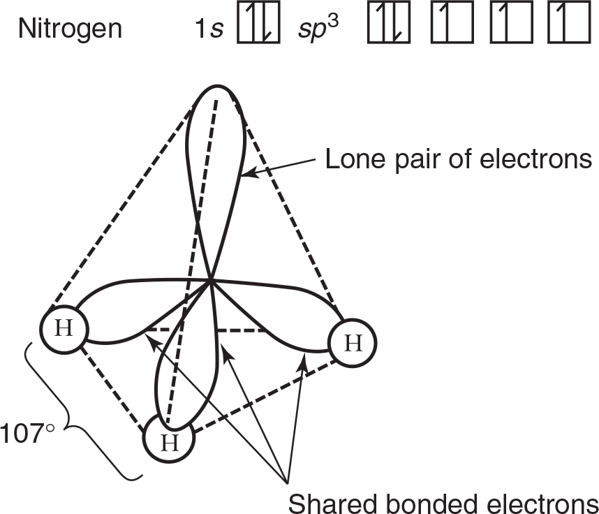
The Lewis structure of ammonia shows that in addition to the three electron pairs the central nitrogen atom shares with the three hydrogen atoms, it also has one unshared pair of electrons:
VSEPR theory postulates that the lone pair occupies space around the nitrogen atom just as the bonding pairs do. Thus, as in the methane molecule shown in an example in the preceding section, the electron pairs maximize their separation by assuming the corners of a tetrahedron. Lone pairs do occupy space, but our description of the observed shape of a molecule refers to the positions of atoms only. Consequently, as shown in the drawing below, the molecular geometry of an ammonia molecule is that of a pyramid with a triangular base. The angle between the bonds is shown to be a bit smaller than 109.5° found between the bonds in methane. This occurs because not only do lone pairs occupy space as bonding pairs do, they also occupy a bit more space as lone pairs are associated with only one nucleus. This spreading out places a bit more repulsion on the bonding pairs and constricts the bond angle by a small degree. The general VSEPR formula for a molecule such as ammonia (NH3) is AB3E, where A replaces N, B replaces H, and E represents the unshared electron pair.
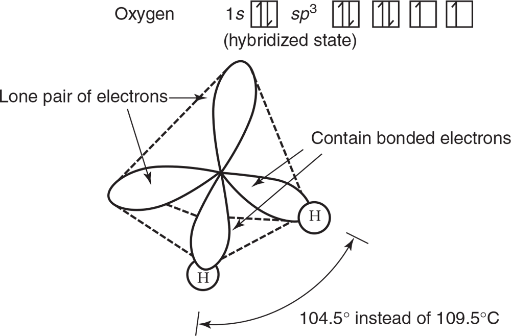
A water molecule has two unshared electron pairs and can be represented as an AB2E2 molecule. Here, the oxygen atom is at the center of a tetrahedron, with two corners occupied by hydrogen atoms and two by the unshared electron pairs, as shown below. Again, VSEPR theory states that the lone pairs occupy space around the central atom but that the actual shape of the molecule is determined only by the positions of the atoms. In the case of water, this results in a “bent,” or angular, molecule. An even smaller bond angle is shown in Figure 3.11 compared to ammonia, due to two lone pairs spreading out in space a bit more than the bonding pairs.
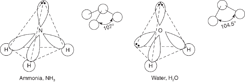
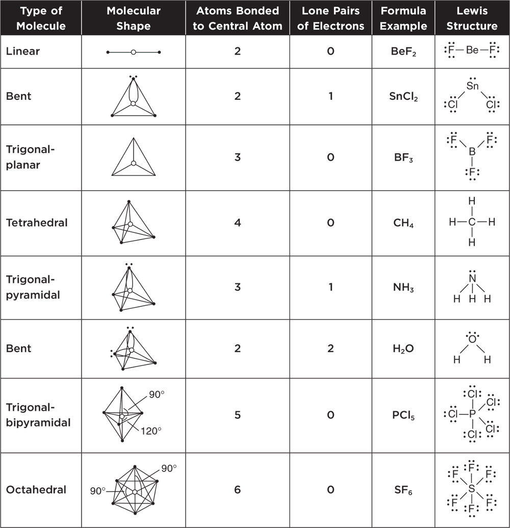
Table 3.2 summarizes the molecular shapes associated with particular types of molecules. In VSEPR theory, double and triple bonds are treated in the same way as single bonds. It is helpful to use the Lewis structures and this table together to predict the shapes of molecules with double and triple bonds as well as the shapes of polyatomic ions.
Table 3.2 Summary of Molecular Shapes
Know these molecular and Lewis structures.
The combination of the molecular geometry, the polarity of the bonds, and the placement of unshared pairs of electrons all contribute to the overall polarity of a molecule. A polar molecule has an uneven distribution of charge, while a nonpolar molecule is balanced concerning the electrical charge. Molecules of ammonia and water lack symmetry with regards to their charge distribution. They are polar molecules as shown in Figure 3.12.
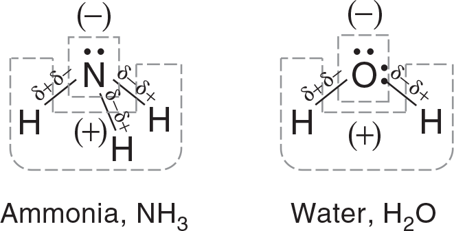
In ammonia, the lone pair on the top of the molecule in combination with the polar bonds make the nitrogen side of the molecule negative. The hydrogen side of the molecule is positive as it lacks lone pairs. So the hydrogen end of each bond is partially positive. Similarly in water, the oxygen side of the molecule is negative and the hydrogen side is positive.
As seen in Figure 3.13, Carbon tetrachloride (CCl4) and boron trifluoride (BF3) are nonpolar molecules as their charge distribution is balanced. Despite the polar bonds in both molecules and the lone pairs in BF3, the symmetrical molecular shapes of each cancel out the polarity of the bonds.

For many molecules, the configurations derived by VSEPR theory could not be realized unless changes in the electron orbitals of the connecting atoms took place. The valence electrons in atoms are not set up to produce the kinds of orbital overlap that result in a covalent bond at the angles we find when analyzing the molecules. Therefore, in the presence of other atoms, the electron energy states that are possible (reflected by new orbital possibilities) are changed. This modification of the types of orbitals available to the valence electrons when atoms are bonding to other atoms is called hybridization. Briefly stated, this means that chemists envision that two or more pure atomic orbitals (usually s, p, and d) can be mixed to form two or more new hybrid atomic orbitals that are identical and conform to the known shapes of molecules. Hybridization can be illustrated as follows:
Spectroscopic measurements of beryllium fluoride, BeF2, reveal a bond angle of 180° and equal bond lengths as described in Figure 3.14.
The ground-state electron structure of beryllium is shown in Figure 3.15:

This configuration of valence electrons makes it seem like beryllium is not able to form two identical bonds as seen in Figure 3.14. The valence electrons are paired and not available to overlap with two other electron orbitals to form two covalent bonds. To accommodate the experimental data, we theorize that a 2s electron is excited to a 2p orbital; then the two orbitals hybridize to yield two identical orbitals called sp orbitals. Each contains one electron but is capable of holding two electrons. The process is described graphically in Figure 3.16.

Boron trifluoride, BF3, has bond angles of 120° and bonds of equal strength. To accommodate these data, the boron atom hybridizes from its ground state of 1s2 2s2 2p1. As seen in Figure 3.17, one 2s electron is excited to a 2p orbital. The three involved orbitals then form three new, identical sp2 orbitals.

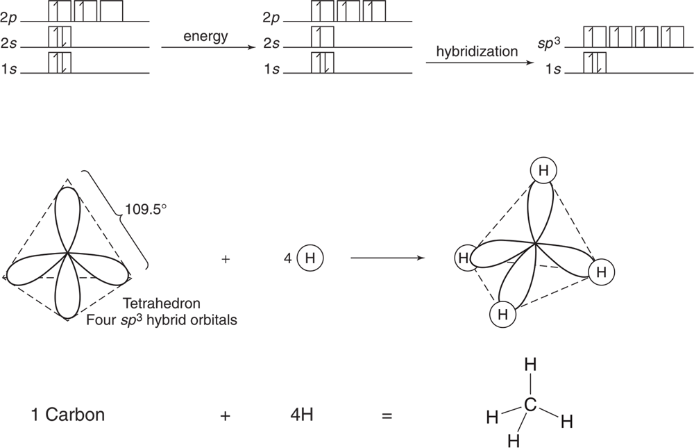
Methane, CH4, can be used to illustrate this hybridization. Carbon has a ground state of 1s2 2s22 p2. One 2s electron is excited to a 2p orbital, and the four involved orbitals then form four new, identical sp3 orbitals as seen in Figure 3.18.
In some compounds where only certain sp3 orbitals are involved in bonding, distortion in the bond angle occurs because of increased unbonded electron repulsion as previously mentioned. Examples are shown in Figures 3.19a and 3.19b.
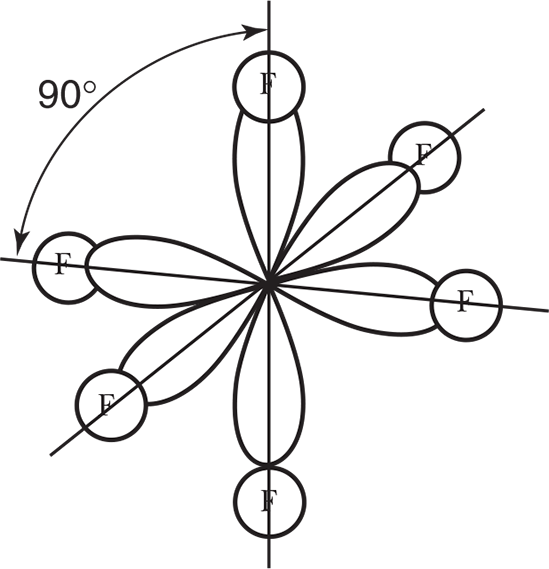
These orbitals are formed from the hybridization of an s and a p electron promoted to d orbitals and transformed into six equal sp3 d2 orbitals. The spatial form is shown in Figure 3.20. Sulfur hexafluoride, SF6, illustrates this hybridization.
The concept of hybridization is summarized in Table 3.3.
Table 3.3 Summary of Hybridization
| Number of Bonds | Number of Unused Electron Pairs | Type of Hybrid Orbital | Angle Between Bonded Atoms | Geometry | Example |
| 2 | 0 | sp | 180° | Linear | BeF2 |
| 3 | 0 | sp2 | 120° | Trigonal-planar | BF3 |
| 4 | 0 | sp3 | 109.5° | Tetrahedral | CH4 |
| 3 | 1 | sp3 | 107° | Pyramidal | NH3 |
| 2 | 2 | sp3 | 104.5° | Angular | H2O |
| 6 | 0 | sp3d2 | 90° | Octahedral | SF6 |
Know these hybrid orbitals designations and their corresponding shapes.