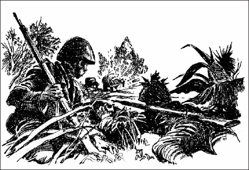
This first section was extracted from a report titled “Landmines, Grenades, and Booby Traps”; only the discussion of booby trapping is provided here:
Four types of booby traps which the Japanese may use in future operations are described. The sketches and explanatory wording were compiled from various Japanese notes. They may have been copied from enemy instructions or they may have been devised by individual Japanese soldiers with technical experience.
1. Device using a parasol. This booby trap is apparently a combined explosive and incendiary device. Opening of the parasol probably breaks the acid vial, which in turn ignites the ignition mixtures.
2. Device using a flashlight. In this type of booby trap, the flashlight switch is used to connect a circuit through an electric detonator. When the switch is pressed, the explosive is ignited.
3. Device using a [tobacco] pipe. It included a safety pin, which, while inserted, prevented the unscrewing of the pipe stem. When the device is placed as a booby trap, the safety pin would be removed; after this, unscrewing of the stem would release the striker pin, which would fire the percussion cap and explosive.
4. Electric booby traps. Watch out for electrically detonated booby traps. Any vehicle, searchlight, generator, light circuit, or other electrical gear can be rigged easily so that the current will detonate a charge. Before any captured equipment is handled, it should be examined for electrical as well as mechanical booby traps.
While the Japanese have made no extensive use of booby traps to date, it is known that the subject has been under study in the enemy training program. (As a safeguard against booby traps, the Japanese have been observed beating trails ahead of them with bamboo poles.)
The Japanese pull-type hand grenade [actually the Chinese 23rd Year (1933), which was copied by a Japanese plant in China] is well suited for booby-trapping purposes, and the enemy may use it extensively in future defensive operations. Several ways in which the Japanese may use this grenade as a booby trap are illustrated below. Most of the diagrams were taken from an enemy publication.
1. With 75mm shell. Figure 50 shows how the Japanese tied a pull-type grenade and a Type 91 (1931) grenade to a 75mm shell to form an improvised booby trap. This combination was found by our troops during recent operations in the South Pacific. The pull-igniter string of the pull-type grenade was tied to some vines which were stretched between two trees. A person or a vehicle striking the vines would have activated the booby trap, which was hidden in some grass nearby. Detonation of the pull-type grenade would have set off the shell and the Type 91 grenade. In improvising booby traps similar to the above, the Japanese are likely to use any type of high-explosive shell or other type of explosive conveniently at hand.
2. Attached to a rifle. The rifle in figure 51 is connected to the pull-igniter of the grenade by means of a string, cord, or wire. A pull on the rifle will activate the grenade and the attached shell. Instead of the rifle, the Japanese may use any other object they think will be attractive to Allied soldiers. The booby trap illustrated in figure 52 is placed in a shallow hole and then covered. It may also be concealed in grass or bushes.
3. Attached to a door. Figure 52 shows how the pull-type grenade can be rigged to a door. Opening the door will activate the weapon.
4. Attached to loose rocks. This arrangement, figure 53, of the pull-type grenade works on the same general principles as the other types. A wire, string, or cord connects the pull-igniter to one of several loose rocks, which are placed in a road or trail for obstruction purposes. Lifting the rock connected with the grenade will activate it. Here again the grenade may be tied to some other type of explosive at hand to increase the blast effect.
5. Attached to felled trees. This arrangement is practically the same as in figure 54. The grenade, tied to a mine in this case, is attached to one or more of the felled trees by means of a vine or string. Instead of trees the enemy might use almost any type of obstructing material.

The Japanese often mined or booby-trapped supply routes and waited for Allied trucks to set them off. They would then attack the stalled convoy, mainly with the intention to loot it for rations.
The following Japanese booby trap reports were extracted from various 1944 sources:
1. The March 1944 Intelligence Bulletin briefly discussed booby traps found by the Marines on Betio Island, Tarawa Atoll in the Gilbert Islands in November 1943. The Japanese left very few booby traps, and these were crudely constructed. A few grenades, with their fuses adapted for instantaneous activation, were found buried in emplacements and tunnels. These grenades [their fuzes] projected about 0.5in above the ground. The door of one captured truck was wired on the inside to a grenade.
2. Marine Corps Technical Bulletin No. 166 (1944) reported a pressure-activated, electrically detonated booby trap. It consisted of an explosive charge placed under floorboards of a building. A section of bamboo was cut to provide two flexible arms in which bolts were fitted to the ends through holes. The section of bamboo was securely fastened to a support beam under the floor. An electrical wire was attached to each bolt. One led directly to the explosive charge. The other was attached to one terminal on a battery. A third wire was attached to the battery’s other terminal and led to the explosive charge. The two wires leading to the explosive charge were attached to an electrical detonator. The upper arm of the bamboo section and its bolt were placed directly beneath a loose floorboard. When pressure on the loose floorboard was applied, i.e., stepped on, the electrical circuit was closed and the charge detonated.
3. The official Marine Corps World War II history reports that near the landing beaches on Tinian, Mariana Islands in July 1944, the Japanese left booby-trapped cases of sake and individual wristwatches laying about. Veterans of the 4th Marine Division, having just seized Saipan, and earlier Roi-Numar, easily avoided them.
4. This report was extracted from the Australian Military Forces Weekly Intelligence Review No. 116 (spring 1944). Two booby traps set up in dumps have been encountered in the Hansa Bay area on north-east New Guinea. In both cases the enemy has incorporated US 23lb M41 parafrag bombs with nose fuze AN-M120. In one case four parafrag bombs were covered with a sheet of galvanized iron. It relied on the sensitivity of the AN-M120 fuze so that any careless movement of the iron would ignite it. The second booby trap had three US parafrag bombs incorporated as well as a Japanese 50kg (110lb) HE bomb. The 50kg bomb was concealed in a detcord dump. From this, a length of detcord was taken and this in turn had a detonator non-electric Type 3 [not to be confused with the Type 3 pressure-firing device mentioned in Section G3 below] with a length of safety fuse to which a detonator was fastened. A tripwire ran from the detonator and was attached to a coil of detcord. Three branch lines ran from the main length of the instantaneous fuse, each to one parafrag bomb. The following conclusions were arrived at after examination:
a. In the first case the trap would most likely have caught souvenir-hunters, but the trap was quickly recognized as such by Royal Australian Engineers personnel.
b. The second case was recognized by the badly concealed instantaneous fuse. It is doubtful if the instantaneous fuse would have detonated the parafrag bombs, but the sudden shock might have caused the sensitive AN-M120 fuze to function.
Although the Japanese have actually used only a comparatively few booby traps to date, they are known to have devised several types, principally by rigging fragmentation grenades in various ways. The enemy is known to have at least five types of such grenades, all of which can be adapted for booby-trapping purposes. Japanese mines and artillery shells also have been improvised for use as booby traps.
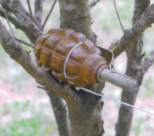
Even more simple than the trap opposite, a lever-activated grenade could be set in a forked tree limb. It usually required the bark to be shaved away to ensure the grenade was pulled smoothly out of the fork by pressure against the tripwire. Such traps would be carefully camouflaged with small leafy twigs.
1. Details of tube-type
a. Construction. The tube itself is made of steel, iron, bamboo, or any other suitable material. It is about 15in long, with a diameter large enough to admit a grenade (Type 91 [1931] grenade is shown in the diagram). Three holes are drilled through the tube to accommodate the suspension wire (1), the safety wire (2), and the support wire (3). The grenade is placed in the tube. The base of the tube is closed by use of a stone or a piece of iron, while the upper opening is covered with similar material as a protection against rain. To complete the rigging process, the tube is strapped to a stake which is driven in the ground.
b. Operation. The support wire (3), which holds the grenade in place during the assembling process, and the safety wire (2) are removed at the same time. The grenade is now held in place by the suspension wire (1). When this wire is removed the grenade falls down the tube and, upon hitting the hard base, the firing pin is forced into the cap. This causes the detonation of the grenade in 4 to 8 seconds.
c. Ways of rigging:
(1) Spring method. A cross wire at a height of about 1ft is used. Attached to the cross wire is another wire, which is also attached to the suspension wire. When the cross wire is pulled, it will extract the suspension wire. To allow for the movement of the cross wire, a spring is attached to the end of the cross wire which is opposite to the direction of the pull. The same principle is used when it is necessary to set a booby trap around a corner or a curve. The only change is that a bent nail is used as a pulley.
(2) Weight method. The spring used in the spring method is substituted by a weight, which allows for two directions of movement. When the cross wire is pulled the weight is lifted, thus causing one movement, and, when the cross wire is cut or loosened, the weight falls to the ground and causes a movement in the opposite direction. Either movement will withdraw the suspension wire.
(3) Stake method. In this method a stake or limb which has elasticity and weight is used. The tree or stake is placed in such a manner that the cross wire holds it in position. When the cross wire is pulled, the elasticity of the tree permits sufficient movement to the cross wire to extract the suspension wire. If the cross wire is cut or freed at the end opposite to that attached to the tree, the latter will fall to the ground and pull out the suspension wire.
3. Details of spring-type
To rig up the Japanese spring-type booby trap, two trees adjacent to each other are selected. A hole is drilled through the trunk of each tree, and a length of easily broken string is passed through the holes. On each end of the string is attached a grenade whose safety wire has been removed. Tied into the string between the grenade and the tree are three nails. When that portion of the string which is suspended between the trees is pulled, the nails prevent the movement of the string. Therefore, if the force is great enough, it will break. This frees the grenades and they fall to the ground, striking a rock, steel plate, or another hard surface placed there. The firing pin is forced into the cap; this action detonates the grenade.
These supplemental notes on Japanese booby traps deal with six improvised types found in the South Pacific and on Kiska Island in the Aleutian Islands.
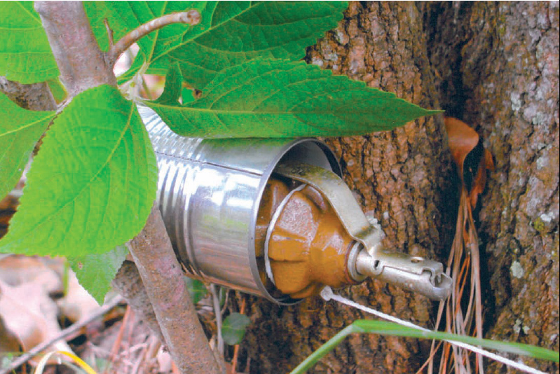
Lever-armed grenades could be inserted in a ration tin fastened to a tree or stake, and the safety/arming pin pulled; a tripwire fastened to the grenade would pull it free, releasing the lever. The tripwire itself could be fastened to an object or thick vegetation so that it was out of immediate view, and camouflaged (obviously, white string is used in this reconstruction simply for visibility in the photograph).
Practically all of the comparatively few Japanese booby traps found to date have been improvised, and many of them have been crudely conceived. In [almost] all cases of actual booby traps found on Kiska, the cords and wires used were not concealed.
[The 5,100-man Japanese garrison embarked aboard evacuation ships in one hour on July 27, 1943, leaving little time to activate booby traps. Nonetheless, three Americans were killed and a number wounded by booby traps.]
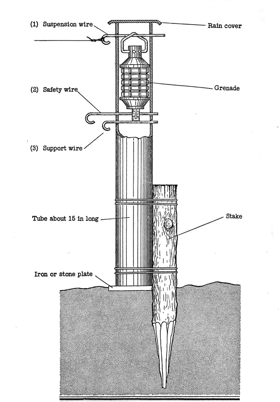
Japanese grenades were percussion-ignited – that is, after the safety/arming pin was pulled a percussion cap (here at the bottom of the grenade) still had to be struck on a hard object such as a helmet, rifle butt or boot heel). This made them more complicated to rig as booby traps. Here a steel pipe or bamboo tube is staked to the ground, camouflaged, and the grenade rigged to drop onto a metal plate or flat stone. The support pin (3) would be pulled first, then the safety pin (2). A tripwire was attached to the suspension pin (1).
2. Southwest Pacific
This type of improvised Japanese booby trap, found in New Guinea, consists of a Type 97 hand grenade and a Type 89 (1929) grenade discharger (“knee mortar”) shell, wired together with the percussion fuze of the shell resting on the base of the grenade and the grenade fuze pointing downward. Apparently it works on the same principle as the enemy tube booby trap. The grenade discharger shell apparently was added to the grenade to increase the effect. However, it is doubtful if the detonation of the grenade would cause detonation of the shell. The whole idea was probably conceived by personnel inexperienced in the technical makeup and effectiveness of explosives.
The grenade discharger shell and hand grenade booby trap combination is designed to utilize a cartridge case, or some sort of tube, as described for the tube booby trap. The suspension string for the booby-trap assembly apparently hangs on a suspension wire at the top of the tube or cartridge case, similar to the tube booby trap arrangement. A tripwire is attached to the suspension wire. Before operation of this booby trap, it is necessary to pull out the safety wire in the fuse of each weapon. Then the application of sufficient pressure against the tripwire pulls out the suspension wire and allows the entire assembly to fall, with the grenade striker hitting a hard surface. Explosion of the grenade depresses the fuse striker on the grenade-discharger shell and, theoretically, causes detonation. The delay train (4 to 5 seconds) was not removed from the grenade which was used in the booby trap found in New Guinea.
If necessary to neutralize this type of booby trap, carefully replace the safety wires.

The Japanese produced numerous types of mines and grenades locally, especially in the Philippines. This explosive-filled wooden box mine – measuring 7½in x 5in x 7½in high – was initiated by a Type 91 (1931) grenade with its percussion fuze pointing upwards. Although intended for anti-vehicle use, it could also be detonated by a boot treading on it.
3. Kiska
a. Piece of bamboo This booby trap was constructed as follows: A piece of bamboo was sawed out to give a clothes-pin effect. Single wires were run along the outer edges and taped securely. Nut and bolt contacts were screwed into the ends. Very slight pressure was required to make contact. The wires ran from contact to a dry-cell battery and on to a charge of explosive. In one instance this consisted of two sake bottles filled with loose picric acid and placed inside a 120mm (4.9in) shell case. In another instance the explosive consisted of a metal-covered block of picric acid weighing 3.5 to 4lb. Electric blasting caps were used as initiators to set off the charges. Two of these booby traps were found, both under boards at the entrance to caves. Little attempt was made to conceal the wiring.
b. Phonograph In booby-trapping a phonograph [gramophone, record-player], the Japanese arranged an electrical contact on the pick-up assembly in such a manner that moving of the phonograph arm to play a record (approximately 0.5in at contact point) would connect the current and set off a charge. Both the charge and battery were under floor boards. No attempt was made to conceal wires leading from the phonograph to the charge.
c. Radio In utilizing a radio for a booby trap, the Japanese removed all except one battery and filled the cavity with blocks of picric acid. Electrical contact wires went from the switch to the battery and to the charge.
d. Antitank mines The Japanese booby-trapped a 7.5cm Type 41 (1908) infantry gun [original text incorrectly called this an antitank gun] by using four Type 93 (1933) antitank mines [a platter-type mine nicknamed the “measuring tape mine”]. A mine was placed in front of, and behind, each wheel; under each mine, six blocks of picric acid were placed. The whole was covered neatly with earth.
4. Burma
a. General In a recent engagement in Burma the Japanese used booby traps on a large scale for the first time. The enemy attempted to block off the approach to a center of resistance by booby-trapping a jungle-covered area 100yd wide and 200yd long, on a high and narrow mountain ridge. Within this area more than 100 booby traps had been laid. The booby traps were all made with British No. 36M Mk 1 grenades, and were extremely simple in principle. The grenade was booby-trapped in two ways:
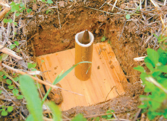
An exceedingly simple Japanese booby trap was constructed of a section of bamboo approximately 2¾in (70mm) long glued to a small baseboard. A small nail was driven through the board, protruding 1/8in (3–4mm) up inside the tube section, and a 7.7mm rifle cartridge was inserted. The device was then buried with only the bullet tip exposed; stepping on it detonated the cartridge and seriously crippled the victim.
b. Tin-can method Part of the side of a tin can is cut to make it adaptable for use as a booby-trap mechanism, and the grenade is placed in the can. One end and a portion of the side of the can are cut away, and a hole is punched in the remaining end of the can for the purpose of attaching a tripwire inside. In preparing the grenade for booby-trapping, the Japanese remove the safety pin, but hold the release handle down so that the grenade will not fire. Then they insert the grenade into the cut-out tin can so that the release handle is held inside the remaining circular portion of the can. Holding the can and grenade together, the enemy places them on the ground. The grenade functions when a pull on the tripwire draws the can away from the grenade and thereby allows the release handle to fly up. Since the grenade is relatively heavy, it remains in place.
As a variation of the tin-can method, the Japanese place the grenade in the can as outlined above, and then balance the can on a tree limb. When pressure is exerted on the tripwire, the can falls over, the grenade drops out (releasing the handle), and the grenade detonates.
c. Tree-fork method [This] works on the same principle as the variation of the tin-can method just described. The space between the tree limbs serves the same function as the can. When the tripwire is pulled, the grenade falls out of the tree and explodes.
d. Tripwires The tripwires used in rigging the Japanese booby traps were strung loose in the heavy undergrowth, and were frequently attached to long vines and creepers. The enemy used ordinary field telephone wire for tripwire, and made no attempt to camouflage either the wires or the grenades, other than the concealment afforded by dense vegetation.
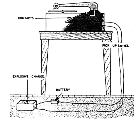
A much more sophisticated Japanese booby trap was electrically activated by moving the arm of a record player to place the needle in contact with the record. The electrical wires in the back were not concealed, however, and the trap was detected through this basic piece of carelessness.
1. Japanese firing device for booby traps or mines (July 1944)
a. General A Japanese pressure-type firing device, for booby traps and other similar uses, was recovered in the Marshall Islands (Kwajalein, Roi-Numar, Eniwetok). This was the first reported instance of the Japanese employing any arsenal-manufactured device for such purposes. Although there is no visible means of securing this firing device either to a prepared or improvised explosive charge, the instrument can be used in a prepared charge with a seating recess, or it can be used in a framework attached to a charge of plastic explosive.
b. Description The firing device is constructed of machined steel, and is finished with a light coating of black paint. The device consists simply of a pressure plate and the body, which has two threaded openings to receive the firing pin holder and the booster. The booster incorporates both the primer and detonator, and consists of 0.1g of lead with a small black powder initiator and 3.5g (0.123-ounce) of tetryl. This booster is powerful enough to detonate Japanese plastic explosive. The firing-pin holder contains a firing-pin and firing-pin spring. When assembled, the firing-pin spring is compressed. However, the firing-pin holder in no way holds or secures the firing-pin. The pressure plate has a wide, mushroom head with a safety pin hole, a shear wire hole, and a slotted keyway. The firing-pin holder bears against a narrow portion of the keyway. The larger opening permits the firing-pin to enter and pierce the primer.
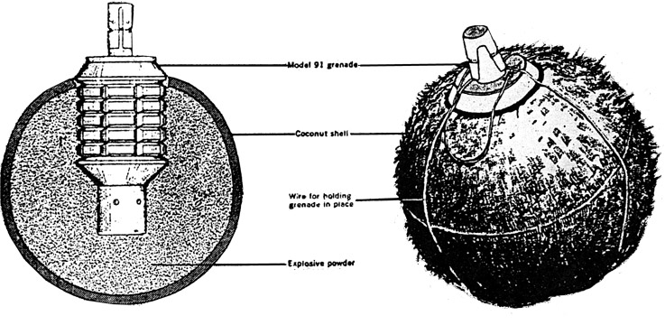
Another crude mine using a Type 91 (1931) grenade was made by filling a coconut shell with explosives and wiring a grenade in place inside, again with the fuze protruding upwards; this was strictly an antipersonnel device. The use of the grenade naturally made all these improvised mines easily locatable by magnetic mine detectors.
c. Functioning After the device has been secured to the charge, the safety pin is withdrawn. The shear wire in the device recovered in the Marshalls can be broken by a pressure of approximately 6lb. As the pressure plate moves down, the large hole in the keyway also moves down until the action of the spring forces the firing pin into the primer. Shear wires are not necessary, and the device may be found without them. Shear wires of various thicknesses were recovered during the operations in the Marshalls.
d. Safety precautions To make this device safe, a small wire or nail should be inserted in the safety pin hole. The firing-pin holder or booster may be removed if no safety pin is present. Serious injury can result from a booster of this size; therefore, the apparatus should be carefully handled until the booster has been unscrewed.
2. Prefabricated booby traps (August 1944)
In the Arakan [coastal region of southwest Burma] the Japanese are now using a small prefabricated booby trap device. It is of very simple construction, and is intended for use with a tripwire. There is a possibility that the Japanese may decide to employ the device extensively, either in its present version or a modified form.
The container for the explosive charge looks like an ordinary tin can. The explosive itself is believed to be picric acid. The firing mechanism, a pull-igniter, is a single unit. Its body is a brass tube, which is threaded so that it can be screwed into the side of the container. It is reported that a loop of wire (or possibly a stout cord) leads into the tube, where it is attached to an igniter wire. This igniter wire, in turn, is imbedded in a matchhead composition. Beyond the matchhead composition are a detonator and a booster charge.
In the jungle it is dangerously easy to mistake a tripwire for a tropical vine. Not only do such vines grow profusely, but their tendrils are quite likely to creep across trails and roads, especially in a rainy season. The two best safeguards against tripwires are to keep trails as clear as possible and to develop the habit of keeping a sharp lookout for booby traps when moving in terrain where the enemy may have had an opportunity to prepare such devices. The Japanese soldiers themselves have learned this lesson, and move with caution over terrain believed to have been occupied by Allied soldiers.
3. Automatic road block (February 1945)
This tactic, a sort of deadfall for trucks, was reported to have been used by Japanese diversionary troops (“commandos”) operating behind American lines in the Philippines. A tree on the side of a mountain road is cut almost through. A steel wire, tied to the tree, is stretched across the road and fastened to another tree so that a passing vehicle that strikes the wire will fell the tree, thus causing damage to the vehicle.
4. Japanese booby-trapping of ammunition dumps (July 1945)
Retiring Japanese troops on the Bataan Peninsula, Luzon, ingeniously booby-trapped three sizable ammunition dumps in the vicinity of Imoc Hill. The existence of probable hidden demolitions in this area was revealed by the shattered bodies of two civilians and a dog, who had paid the price of inquisitiveness. Ammunition dumps at Gapan also had been booby-trapped, and one of these, too, had been detonated by the unwary.

A trap as crude as the deadfalls rigged up since prehistory to catch animals was sometimes effective against vehicles even in World War II. A thin but strong wire cable was strung across a road between one tree and a second almost completely cut through; this was especially hard for a driver to spot in darkness or bad weather, and the impact of a truck might topple the cut tree onto it. With the road blocked, Japanese troops could initiate an ambush.
An investigation of the remaining munitions in both areas revealed that other dumps had been cleverly booby-trapped. The munitions booby-trapped in a typical instance (see accompanying sketch) consisted of 75 boxes of Type 99 (1939) 7.7mm rifle and machine gun ammunition, and 15 boxes of Type 89 (1929) 5cm grenades. The boxes were neatly stacked six high within a revetment cut into the side of a hill. This revetment was only large enough for the munitions. Entrance and encirclement were not possible on the ground level, and inspection could be made only from one end and from above. From the top of the embankment, the site resembled a poor attempt at concealment of a trench. Loose dirt, twigs, and grass had been thrown on top of a roof consisting of two sheets of corrugated iron and a plywood door, presumably from nearby dwellings.
Fastened beneath the main components of the roof to long branches were the strings of six pull-type friction-igniters fixed in box-type mines. These mines were placed directly on top of the stacks of munitions and carried the entire weight of the roof. Therefore, any attempt to move any portion of the covering materials would be likely to pull at least one of the igniters, detonate the picric acid contents of a box mine, and cause the explosion of the ammunition.
Recent campaigns in the Pacific and Asia have shown that the Japanese, when given the time, are not content to retreat without planting booby traps and other explosives to injure personnel and to destroy abandoned materiel. Although the Japanese soldier has been taught to improvise to a great extent with hand grenades and dynamite when preparing his traps and demolitions, the Japanese Army has experimented with some mechanical devices which may be encountered by US troops. Most Japanese booby traps thus far encountered have been constructed with an ordinary hand grenade or friction-type fuse lighter to act as the igniter. However, the Japanese have also experimented with at least four machine-made igniters. Although there has been no reported instance where a Japanese booby trap has been fitted with one of these firing devices, their use should be anticipated. [The “type” designations were assigned by US Intelligence.]
1. Type 1 A simple device [consisting] of a striker held back from a primer by a retaining pin. A tension spring is attached to the striker and, when the retaining pin is drawn, pulls the striker down on the primer cap. When rigged with a charge as a booby trap, a tripwire is attached directly to the retaining pin.
2. Type 2 [This] is a time-delay igniter. A striker, under pressure from a compressed spring, is held back from a primer cap by a thin copper wire fastened from the striker to the opposite end of the igniter. A small glass vial of acid is located in the top of the igniter near the wire. When the vial is broken, the acid corrodes the wire and releases the spring-loaded striker. There appears to be no safety device with this igniter, and the actuating pressure is not known. (The delay time was not reported.)
3. Type 3 [This] is a pressure-type igniter consisting of a primer cap and a spring-loaded striker, the base of which is anchored firmly to the igniter case. A chisel-like pressure shaft is set at right angles to the striker. Pressure on this shaft forces the chisel edge down on the striker base, cutting the striker free so that, under pressure of the spring, it is driven into the primer cap.
4. Type 4 An electric igniter, the Type 4 device is housed in a waterproof rubber tube of undetermined length. It consists chiefly of two parallel metal strips placed one over the other and held apart by blocks of insulating material fixed between the ends. Wires hooked to one end of each strip can be attached to a battery and an electric cap set in the demolition charge. Pressure on the rubber tube presses the strips together, thus closing the electric circuit and detonating the charge.