Chapter 5. GPS, Compass, and Battery Monitor
In this chapter, we are going to cover three accessories that we will add to our drone. Each of these components on its own would make a pretty small chapter, so we thought we would cover all three in a single chapter.
GPS
One feature clearly draws the line between a drone and a model aircraft: the ability to operate using GPS (see Figure 5-1). The addition of this satellite navigation technology allows for a level of control that was simply not possible before. This extra control allowed drone designers to develop flight modes for specific types of flights.

Figure 5-1. 3DR uBlox GPS unit with built-in compass.
Flight Modes
Let’s review a few types of flight modes that GPS allows.
Loiter (position and altitude)
Probably the most-used GPS feature, loiter does exactly what the name implies: it holds the aircraft at a specific location (latitude, longitude, and altitude) at the flick of a switch. When in position hold, the aircraft will self-correct its location if it is changed by any outside forces. For example, once loiter is engaged, the aircraft would automatically fly back to its original location if the wind pushed it away. This is typically within a range of plus or minus two meters when properly configured. The same approach is taken with altitude. Altitude hold is usually within plus or minus three meters, and can use additional sensors beyond just GPS, such as the internal barometer.
Return to Home (RTH) failsafe
One of the best safety features in modern UAV—Return to Home (RTH)—is only possible when GPS is used. This mode allows the aircraft to determine a home location, usually the original takeoff location, and return there under certain failsafe circumstances. Losing radio connection to your aircraft is one common trigger for RTH. This could happen if your radio batteries die while in flight or if you fly outside of the radio’s broadcasting range. Some people also program a dedicated switch on their radio to engage RTH.
Waypoint navigation
A slightly more advanced use for GPS data is autonomous navigation through programmed waypoints. Ground control software uploads a list of navigation instructions to the flight controller, which carries them out, step by step, as a complete mission. This technique is especially useful in the UAV mapping industry, where specific flight patterns need to be flown time and time again. Always confirm optimal GPS performance on your aircraft before attempting to fly via waypoints. If the craft can hold position and RTH safely, it should be more than capable of waypoint flight.
Follow Me mode
The newest use for GPS data in the multirotor world is currently Follow Me functionality. This mode allows a user to send a real-time stream of the user’s location data to the drone, through the use of a mobile app. The drone then uses that location data from your mobile to follow you from a predetermined height and distance. The possibilities for sports coverage alone are fantastic—imagine a camera drone always hovering 20 feet above the quarterback’s head—but Follow Me should be used with caution. Because most small UAVs do not have Sense and Avoid technology, Follow Me mode could cause trouble in tight or congested environments. If you ski under that tree branch, your quad won’t be able to tell it’s there and could fly right into it.
Compass
While GPS allows our drone to obtain a higher level of autonomy, it wouldn’t be worth very much if it couldn’t keep its heading. That is where the compass comes into play. Often bundled together with the GPS into one unit (as in our demo build), the compass tells our drone not only where all the cardinal directions lie, but also which direction it is pointing to upon startup and any changes that happen during its flight.
APM 2.5 Versus 2.6
Depending on how you sourced the parts for your build, you are likely to end up with one of two different versions of the APM flight controller. There are a few subtle differences between the two, but the main thing we are concerned with is the compass. The APM 2.5 used an internal compass while the 2.6 switched to an external compass that is bundled inside the GPS housing. This allowed the sensor to be removed from the inside of the APM housing and placed in a much more suitable environment (magnetically speaking) such as the GPS enclosure. If you have an APM 2.5, don’t fret! There is a fairly simple way to disable the internal compass and take advantage of the newer external units.
Battery Monitor
Another small but very important accessory in our build is the battery monitor (also called the power module in some circles). While some other flight controllers have some form of battery monitoring built in by default—such as an internal power module—APM allows you to add it as an optional sensor. Although it’s optional, we highly recommend that you add one to your aircraft (see Figure 5-2). It provides some of the most important data you could ask for and generally comes with most APMs as part of the basic bundle (depending where you buy it from).

Figure 5-2. Our inline battery monitor collects very important mission data as we fly.
The theory behind the battery monitor is simple: place a small circuit board inline with the main battery lead and allow it to collect critical voltage and amperage information that is fed back into the APM. From there, we can direct the firmware to do a number of different things with that information, such as automatically return to home (RTH) when a certain voltage is reached as a failsafe measure.
Step-by-Step Build Instructions
The following steps will walk you through the installation of the GPS, compass, and battery monitor. While this portion of the build may seem fairly simple from an install perspective, please pay careful attention, because getting these wrong could have a huge impact on your aircraft stability and reliability:
Step 1: Mount the GPS Puck
Installing the GPS puck is probably one of the simplest steps of this entire build. It is important to know that most GPS pucks also contain a compass, which means they have a dedicated front and back. Always make sure that the forward arrow is pointing toward the front of the aircraft. If your GPS component came with a raised mounting bracket, use it (see Figure 5-3). If it didn’t—and you don’t have any way of making one—you can order one from 3D Robotics or the Maker Shed. It is generally considered a best practice to place the GPS puck (with internal compass) high above the rest of the electronics to avoid any magnetic interference. Follow any assembly instructions that came with your mounting bracket, then attach the bracket to the top of the drone frame as close to the center of gravity as you can. Apply a generous amount of double-sided tape to the bracket—or find a way to screw it in place—in order to hold it in place.

Figure 5-3. 3DR makes a nice mast for the uBlox GPS.
For our build, we made our own GPS mount out of an extra 37-mm standoff and a 3D-printed base (see Figure 5-4). That is the unit you will see in most of the remaining figures in this chapter. Depending on which GPS unit you are using, several open designs are available on the Internet for 3D-printable mounts.

Figure 5-4. We like to keep things simple with this DIY GPS mast.
Step 2: Connect GPS and Compass to the APM
If you bought the 3DR uBlox GPS for your build, it should have come with two (possibly more) small cables that allow you to connect it to the APM. Remove them from the bag and inspect them carefully. This GPS is able to work with a few different autopilot systems, so it will likely ship with a variety of cables to cover all the bases. The two that you want to find are identified as a 4-position cable and a 5-to-6-position cable. This may sound a little funny at first, but it’s pretty simple. The positions indicate how many wires are able to be fitted into the end of the plug. In our case, we have one cable that has four positions on both ends with four wires that run between. This one is for the compass (magnetometer). Our second cable has a 5-position plug on one end and a 6-position plug on the other with five wires that run between them. That’s right, one of your plugs will have an empty spot in the plug; this is normal, so do not be alarmed. We will get into why that is the case later, but for now, have a look at the cables we will be using in Figure 5-5. If you did not get these cables with your compass, tell your vendor immediately, especially if you bought the APM and GPS together from the same store!

Figure 5-5. Make sure that you have the right cables for the job.
Now that we have identified the proper cables, let’s take a look at the GPS unit itself. There is not much to it; it’s a small black square with two ports on the left side labeled GPS and MAG. Upon closer examination you will notice that the GPS port has six small pins inside it and the MAG port has four. Is this starting to make sense now? The 5-to-6-position GPS cable will plug the 6-position end into the GPS port, while the compass cable will take either end of our 4-position cable (see Figure 5-6).

Figure 5-6. The two ports on the side of our GPS puck.
MAG Port
In case you haven’t figured it out on your own, the MAG port on the side of the GPS puck is labeled as such because it is short for magnetometer. This is the technical name of the sensor that provides our compass functionality.
Now that we have one end of our cables plugged into the GPS puck, let’s plug the other ends into the APM. Find the 5-position plug that is connected to the GPS port (on our GPS puck) and plug it into the GPS port on the APM (next to the forward arrow on the top). Now, take the remaining 4-position plug and insert it into the I2C port (short for inter-integrated circuit and pronounced I-squared-C). Refer to Figure 5-7 for details on how these two cables are connected.
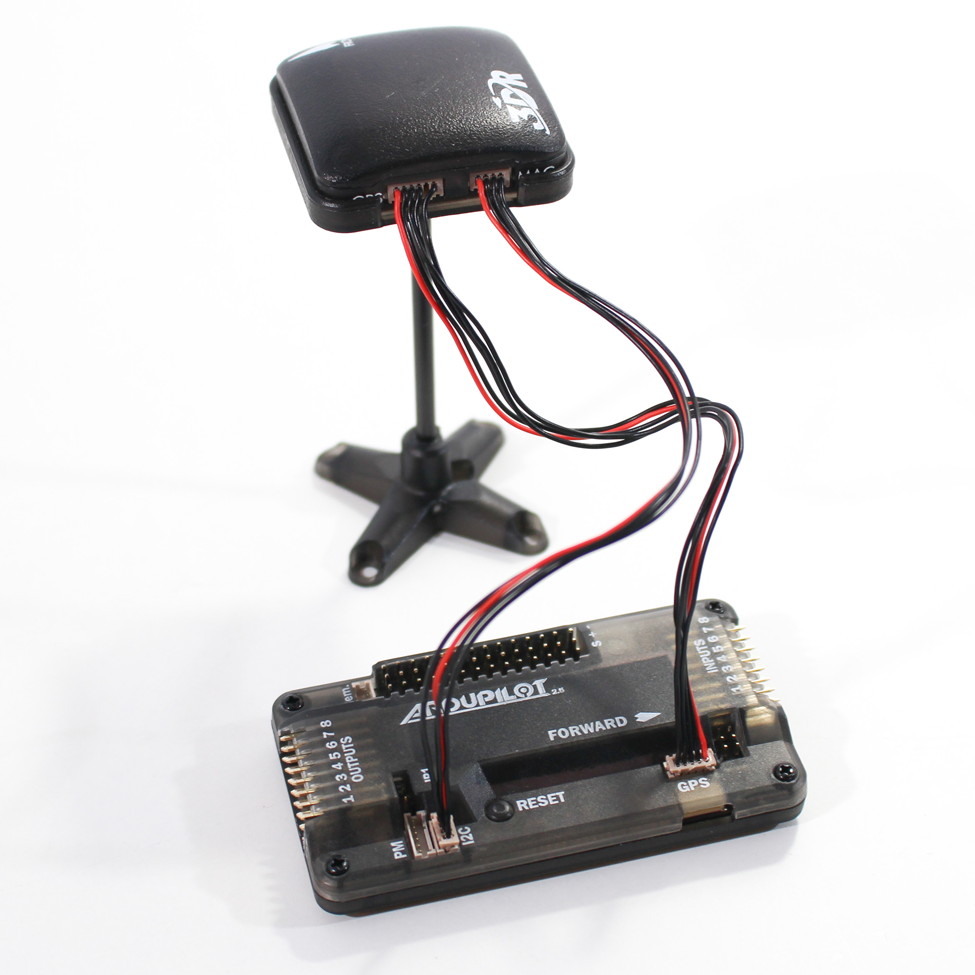
Figure 5-7. Our GPS and compass (magnetometer) plugged into the APM.
Careful with the Plugs!
It can be difficult working with these types of sensor plugs. They are very delicate and can be damaged if you unseat them once they are plugged in. If you are working on your drone and have to plug and unplug these for whatever reason, take caution! We recommend using a tiny flat-head screwdriver to gently lift them out of their seat while pulling ever so slightly on the cable itself. Do not pull too hard! The wire will pull itself out of its plug position if you are not careful. It happened to us several time before we got used to working with these types of cables. Over time, it will become easier for you, but you should take extra caution when you first start working with them.
Step 3: Install the Battery Monitor
Finally, we will install our battery monitor. Remember, this is an optional accessory. If you are choosing to leave yours off—maybe you want to save a few grams of weight—then skip this step. That being said, there is a lot of value in having this important data monitored during the flight of your drone, and we encourage you to go forward with this part of the build.
The overview of the install is quite simple: first, we plug our main battery lead from the power distribution board (or power harness) into our battery monitor, then we plug the 6-position plug into the PM port on the APM. The flight battery will now plug into the battery monitor rather than the main power lead coming off the power distribution board. Figure 5-8 shows the battery monitor plugged in on the bench.

Figure 5-8. Our battery monitor plugged in on the bench, speaking to the APM over a 6-position cable that plugs into the PM port.
Start off by plugging the battery monitor into the main battery lead from the power distribution board (see Figure 5-9). This is the same lead that you would normally plug your battery into if you weren’t using a battery monitor.

Figure 5-9. Your battery monitor should have the same type of plugs as your main battery lead (XT-60, in our case).
Next, we need to mount our battery monitor on the back portion of our frame (see Figure 5-10). Start by pushing the original battery lead plug into the space between the clean and dirty frames all the way in the back of the frame. It should fit in there nice and snug with the monitor lying across the bottom of the clean frame. Be sure to route the 6-position cable across the bottom of the frame in through the same holes that you routed the ESC plugs earlier in the book. This cable will be long enough to reach the PM port on the APM, its final destination.
Because the leads on our battery monitor are so short, we can attach the monitor itself to the back end of the frame with a zip tie or two leaving the new battery lead exposed and easily accessible to our flight battery (see Figure 5-11).
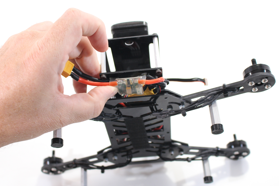
Figure 5-10. Getting our battery monitor into position and ready to be fastened to the frame.

Figure 5-11. The new battery lead is accessible to the flight battery.
Now there’s only one thing left to do: plug the 6-position cable that comes out of your battery monitor into the PM port as shown earlier in the chapter. Make sure that the red wire within the cable is on the right side (as indicated by the port label).
Wrapping Up
That’s it for the GPS, compass, and battery monitor. Later in the book, we will use the flight controller software to confirm that the GPS is picking up the signal that we are looking for. We will also take a look at the settings for the battery monitor. For now, move on to the next chapter.