Figure 12.1 Scanning electron microscope images of commercial synthetic bone grafts: (a) NovaBone and (b) Actifuse.
Chapter 12
Bioactive Glass as Synthetic Bone Grafts and Scaffolds for Tissue Engineering
Bioactive glass was invented in 1969 by Larry Hench. Since then, bioactive glasses have been seen to bond to bone and to degrade safely, releasing bioactive ions that can stimulate stem cells and bone cells to produce new bone. However, few products have been released to market (Chapter 2). Bioactive glass has been lagging behind other bioceramics in terms of numbers of products and amount of use worldwide. What are the reasons for this? It is not down to performance: in vivo studies show that bioactive glasses outperform bioactive ceramics such as calcium phosphates and synthetic hydroxyapatites (Chapter 2). So what has been the problem?
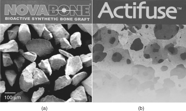
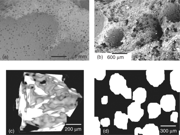
Bioactive glass began commercial life as a particulate bone filler in dental applications in 1995 and then became an orthopaedic product a few years later. Surgeons mix the sachet of bioactive glass powder with blood from the bone defect of the patient and push the mixture into the defect as a putty. One of the main problems for lack of widespread use of bioactive glass in orthopaedic applications has been the lack of products available. Several compositions, such as Bioglass®—the original Hench formulation—available as PerioGlas® and NovaBone® (NovaBone Products, USA), Biogran® (Orthovita, USA), BonAlive® (BonAlive, Finland) and StronBone™ (RepRegen, UK) exist, but they are all particulates (Figure 12.1a). So let us take a look at the current market-leading synthetic bone graft: Actifuse® (Apatech, UK). Actifuse is a synthetic hydroxyapatite. What sets it apart from other synthetic hydroxapatites (of which there are many commercial products) is that it contains a small amount (0.8 wt%) of silicon. It is silicon-substituted hydroxyapatite. Traditional synthetic apatites are highly crystalline ceramics that degrade slowly and bond to bone slowly. The small amount of silicon in the Actifuse formulation creates defects, increasing the number of grain boundaries and reducing crystallinity just enough to increase degradation. Silicon was chosen because of studies that showed that a diet containing silicon is necessary for healthy bone growth and because bioactive glass was known to be more bioactive than the bioactive ceramics. One reason for the latter was that the glasses release soluble silica, which stimulates cells to produce more bone. What sets Actifuse apart from bioactive glass is that it consists of porous granules (Figure 12.1b). The pores are of a similar size to those in porous bone (Figure 12.2), which means the granules mimic the macrostructure of the cancellous or trabecular bone.
Figure 12.1 Scanning electron microscope images of commercial synthetic bone grafts: (a) NovaBone and (b) Actifuse.
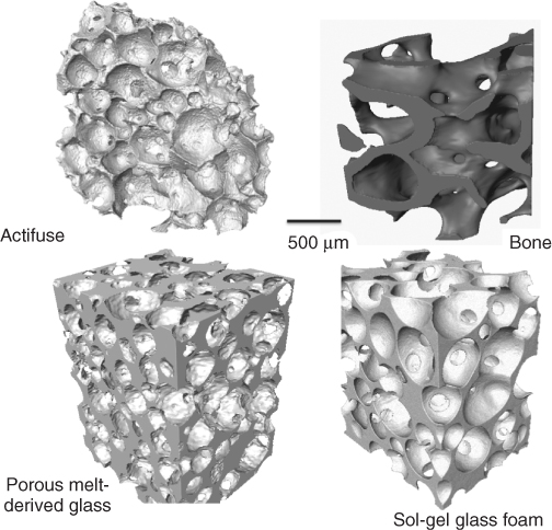
Figure 12.2 Three-dimensional images, obtained using X-ray microtomography, of porous networks in Actifuse, cancellous bone and bioactive glass foams (melt-derived and sol-gel derived). (Images by Sheng Yue. Copyright (2012) Sheng Yue.)
Regenerative medicine is using materials (implants), cells, drugs or a combination of these to stimulate the body to regenerate diseased or damaged tissue to its original state and function. For example, a tumour is removed from a bone, leaving a large defect. The bone would have been able to heal itself if the defect was small, like a routine fracture, but if the gap is large, the cells cannot ‘sense’ the other side of the defect and the defect remains, or is filled with soft tissue. A temporary template (scaffold) is needed that can help the cells. The scaffold acts as a framework and guide for the cells that usually regenerate the bone. Bone regeneration is considered the future for bone repair, but in some ways it is already the present.
Half a million bone graft operations are performed in the USA every year, and just over half that number are carried out in Europe. Bone defects are caused by a range of clinical indications: congenital defects (e.g. cleft palates), trauma, tumour removal or non-union of fractures. Another common procedure that needs bone graft is spinal fusion. In this case, there is not really a bone defect. The clinical indication is a slipped (herniated) intervertebral disc (IVD). The IVD is made of cartilage, which regenerates at a much, much lower rate than bone. When the IVD is severely herniated and has to be removed, treatment is to replace the IVD with a metal or polymer cage filled with bone graft. The bone grows into the cage and fuses with the bone graft. The idea is that the implant fuses the neighbouring vertebrae, immobilising them. This reduces pain but also restricts movement.
Surgeons currently routinely perform bone regeneration operations, but the scaffold is the patient's own bone, termed autograft. The bone is usually harvested from the pelvis, but in the case of spinal fusion operations, bone spurs are often harvested from the vertebrae. Autograft bone is an ideal material for regenerating bone.
Unfortunately, there are many drawbacks to using the patient's bone. The most important is that there is limited supply of bone that can be utilised without causing problems at the host site. The body is not wasteful in bone production, so there is not much excess bone available. One of the main functions of bone is to support load. If a situation occurs where excess bone is made, the excess bone is likely not to be under load. If this happens, the body will take the bone away by osteoclast action. This is why astronauts need to exercise excessively in space to prevent loss of bone density, as the lack of gravity means bones are not loaded. This is an important consideration for bone graft design.
Harvesting healthy bone for grafting also creates another defect that needs to be healed (without the help of more bone). The healing of this defect is extremely painful and long. Patients generally feel a lot of pain at the donor site and one in four patients will experience complications at the defect site long after the operation. Some will require revision surgery of the harvest site, which is not ideal for the patient, the healthcare service or the economy.
These problems are the driving force for the need for synthetic bone grafts that can perform as well as (or better than) autograft. The devices must regenerate bone defects without the need for graft operations so that patients can heal quickly and pain-free, returning to their normal lives and, importantly for the economy, place of work, more quickly.
An artificial bone graft that can replace the need for grafts would have a massive impact on the global economy. The device market itself is thought to be worth $2 billion per year without taking into account the economic impact of reduced operating costs and faster recovery times.
Many artificial bone grafts are designed to replace or augment the bone and stay there for a long time rather than regenerate the bone to its original state and function. Examples are porous titanium or tantalum metal constructs. Metallic scaffolds have the advantage of high strength and toughness. Toughness (resistance to crack propagation) is important when the scaffold is to be exposed to cyclic loads, which are commonplace in skeletal tissue. However, metals are usually bio-inert and intrinsically not bioactive, so fibrous encapsulation may occur. The metal will also stay in place long-term, meaning that naturally healthy bone will never re-form. The body is likely eventually to reject the implant, but time scales are variable.
Surgeons ultimately want something that works and can be implanted with ease. They would like to be able to take a packet off the shelf, remove the implant, shape it, press or inject it into the defect, and watch as it fills the space. They would like the implant to take load and share load with the host bone, immediately. This is so the patient can load their bones, keeping them healthy, but also so bed space is not occupied for too long. Then, over time, they would like the scaffold to disappear as the bone regrows.
An ideal synthetic bone graft would regenerate a bone defect and leave no trace of an implant, and it must possess the following characteristics:
There are numerous synthetic bone graft materials as commercial products, but none that fulfil all the criteria listed above. Metals are not bioactive and generally do not degrade, although magnesium is being investigated as a potentially biodegradable metal for stent applications. Bioceramics (calcium sulfates and calcium phosphates) are usually chosen because of their long track record in clinical use. Bioactive glasses have the potential to fulfil most of these criteria. But currently their commercial products are limited to particles. Why is this?
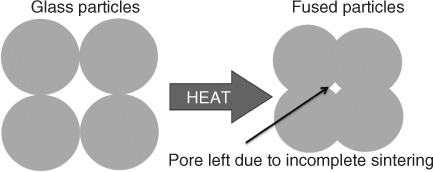
All processing techniques for making porous scaffolds from particles involve sintering. Sintering is the fusion of particles at high temperature (Figure 12.3). Raising the temperature above the glass transition temperature (Tg) causes local flow of the glass and allows particles to fuse. However, to maintain the amorphous glass structure and properties, the temperature must not be raised above the crystallisation onset temperature (Tc,onset). Unfortunately for the original Bioglass composition (46.1 mol% SiO2, 24.4 mol% Na2O, 26.9 mol% CaO and 2.6 mol% P2O5), the low silica content causes Tg and Tc,onset to be too close together, so it is not possible to sinter the glass without crystallising, which leads to the formation of a glass-ceramic and reduction in bioactivity. Therefore, only Bioglass particles are available commercially (Figure 12.1). Only now have researchers been able to understand the relationship between glass structure, composition, glass transition, crystallisation and bioactivity. In other words, it is quite a challenge to design a glass composition that can be sintered without crystallising but also remains bioactive. One line of thought is that the network connectivity should be approximately 2 (like Bioglass) for a glass to be bioactive (Chapter 2). However, glasses with network connectivity of 2 have the problem of easy crystallisation. Increasing the silica content reduces the tendency of a glass to crystallise, but this reduces the degradation rate and bioactivity. We therefore need to ‘trick’ the glass network by incorporating a variety of network modifiers, substituting for calcium and sodium, to keep network connectivity constant. The variety of modifiers makes crystallisation energetically unfavourable, as the structure is more difficult to organise.
Figure 12.3 Schematic of the principles of sintering glass particles.
New compositions have been designed not to crystallise on sintering. One is 13-93 (54.6 mol% SiO2, 6 mol% Na2O, 22.1 mol% CaO, 1.7 mol% P2O5, 7.9 mol% K2O, 7.7 mol% MgO), which was developed in Finland by Brink and co-workers. This glass takes seven days to form a hydroxycarbonate apatite layer in simulated body fluid tests (Bioglass particles formed the same layer within 8 hours). This is because the network connectivity is higher in glass composition 13-93 compared to 45S5 Bioglass owing to the increased silica content.
In order to obtain a similar result without compromising bioactivity, ICIE16 (49.46 mol% SiO2, 36.27 mol% CaO, 6.6 mol% Na2O, 1.07 mol% P2O5 and 6.6 mol% K2O) was developed by Elgayar and co-workers.
Sintering alone cannot make pores large enough to create a pore network that can encourage vascularised bone growth. Pores that are left behind (Figure 12.3) are considered defects and sources of weakness (crack nucleation sites and sites of stress concentration). The aim is to create large pores with diameters in excess of 500 µm with interconnects greater than 100 µm, while having highly sintered struts that provide as much strength as possible. The aim is to mimic the porous structure of cancellous bone (Figure 12.2).
The most common method for making porous ceramics is to take a particulate and pack the particles around a sacrificial template of some kind (Figure 12.4). During sintering, the particles will fuse together. The template can be either washed out or burned out, depending on what is used, leaving pores. The pore size and interconnectivity depend on the template.
Figure 12.4 Schematic of the porogen or space holder method for producing porous materials.
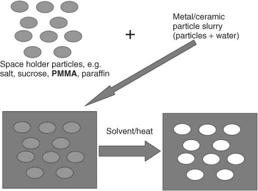
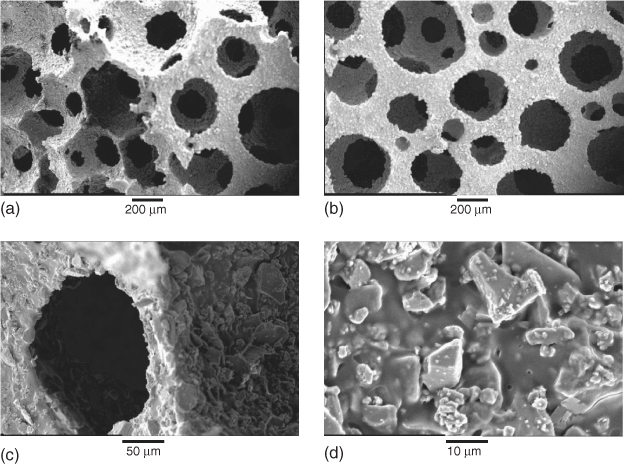
The space holder or porogen method is the most common. Sacrificial particles are used, either soluble particles, for example, salt or sucrose, or combustible, for example, poly(methyl methacrylate) (PMMA) microbeads (Figure 12.4). Combustible polymers are usually used for ceramic synthesis. However, the burning out of the sacrificial polymer step must be done carefully. For processing bioactive glass, washing with aqueous solutions is avoided to prevent the start of glass dissolution and the bioactivity mechanism cascade. However, if not enough oxygen reaches the combustible polymer, residual carbon will be left behind, leaving a black colour and reducing the sintering efficiency. This is known as coring. The use of PMMA reduces coring because it leaves little residue as it burns. High oxygen content in the furnace and sintering samples as small as possible (reducing the path length that oxygen molecules would need to travel) can also help to reduce coring. The advantage of the space holder technique is that it is simple and can be up-scaled to production easily. Pore size is largely determined by particle size of the sacrificial polymer, but it is difficult to maintain a homogeneous distribution of the polymer spheres and therefore interconnectivity is low and poorly controlled (Figure 12.5).
Figure 12.5 Images of porous bioactive glasses produced by the space holder method, using PMMA microspheres (diameter ∼500 µm) at a glass-to-polymer ratio of 50 : 50. (a) Low-magnification SEM image showing isolated spherical pores. (b) SEM image showing isolated pores (not interconnected). (c) 3D reconstruction from X-ray microtomography (µCT) imaging, showing irregularity of pores. (d) 2D µCT projection showing isolated pores. (Images by Zoe Wu and Sheng Yue. Copyright (2012) Zoe Wu and Sheng Yue.)
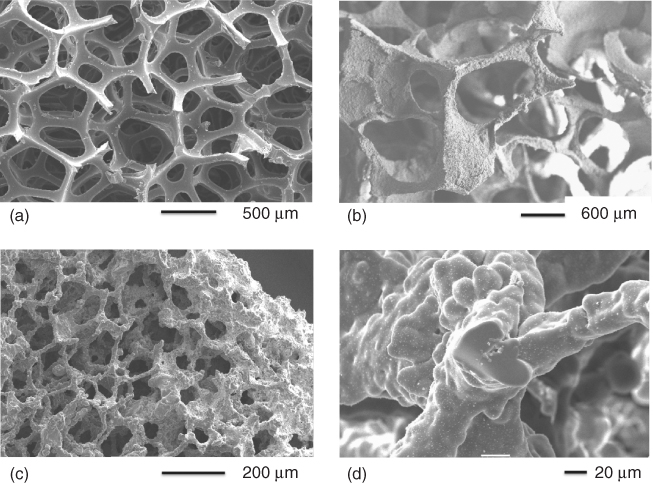
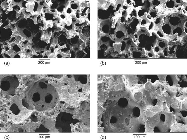
Interconnectivity is improved through using sacrificial polyurethane foams rather than spheres. Polyurethane foams are used to make common open-pore (open-cell) foams such as those used in sofas and armchairs. They are readily available in different ranges of pore sizes, although they are usually quoted in pores per inch. Figure 12.6(a) shows a scanning electron microscope (SEM) image of a polyurethane foam. The struts are thin and the pores are large and well connected, so much so that it is difficult to tell what is an interconnection and what is a pore. The polymer foam can be immersed in slurries of glass or ceramic particles so that the particles coat the polymer foam. The aim is that, after sintering, the glass will take the shape of the foam. The main challenge in the process is to ensure that the polymer is well coated but not full of excess particles. If there are excess particles, they will block the pores. The common way to remove excess powder is to squeeze it out of the foam, literally between two fingers. Industrial companies must have an automated process for this as reticulated ceramic foams are mass produced for other applications. After the excess powder is removed, the foams are heated at 250 °C to burn out the organic components (pyrolysis) and sintered for 3 hours. For glasses, the sintering temperature is chosen depending on the glass composition, as it must be in the sintering window between the Tg and Tc (usually around 700 °C). Figure 12.6 shows SEM images of the polymer foam (Figure 12.6a) and the resulting glass scaffold (Figure 12.6b). Polymer foam replication is successful in that it produces a very open interconnected structure. Polymer foams are easy to produce or purchase, and pore size is very much determined by the polymer foam specifications, which means foams of different pore sizes can be easily produced. Figure 12.6(c) shows a glass foam that was produced from a polymer foam of lower pore size. However, up-scaling is challenging. Polymer removal also leaves hollow foam struts (Figure 12.6d), which means that mechanical properties are low.
Figure 12.6 SEM images relating to the polymer foam replication process: (a) a sacrificial polyurethane foam template; (b) a porous glass foam after removal of the polymer template and sintering; (c) a porous glass of lower pore size; and (d) cross-section of a hollow strut caused by the polymer removal. (Images by Zoe Wu. Copyright (2012) Zoe Wu.)
A way to avoid having hollow struts is to directly foam the slurry so a polymer foam is not needed. This technique involves the use of surfactants to stabilise bubbles that are created in a liquid by vigorous agitation. The bubbles must then be gelled (solidified) to maintain the porous structure. This is a key step in the process, as the bubbles must be maintained, but solidified. The process is similar to what is used to produce Actifuse, and is the latest technique for producing porous bioactive glasses with similar interconnected pore structures and mechanical strengths to porous bone.
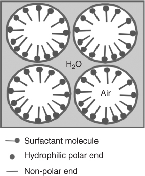
For direct foaming, either melt-derived or sol-gel glasses can be used. Melt-derived glasses are foamed by the gel-cast foaming process and sol-gel by the sol-gel foaming processes. The processes have many similarities. The main ones are that in both cases a solution or slurry is foamed under vigorous agitation with a surfactant to form bubbles. The bubbles are gelled and are poured into moulds immediately prior to gelling. The main differences are that the melt-derived glass gel-cast foaming process uses in situ polymerisation to gel the bubbles. The sol-gel process is different in that, rather than needing a polymer to do the gelling, it gels itself, which simplifies the process. Surfactants are ‘surface active agents’. They are molecules that have a hydrophilic end and a hydrophobic end and are the active ingredients of detergents. When surfactants are added to water, they lower the surface tension because the hydrophilic end of the molecule affiliates itself with the water, and the hydrophobic end is in the air. This stabilises the bubbles (Figure 12.7) that grow by agitation.
Figure 12.7 Schematic on the role of surfactant in stabilising air bubbles in agitated water.
For melt-derived glass, fine particles (<38 µm) of a sinterable composition, such as 13-93 or ICIE16, are added to water to produce a slurry. A surfactant is then added and the slurry is foamed under vigorous agitation. This could be with a whisk, rather like making a meringue. Figure 12.8 shows a schematic of the process. For the process to succeed, the viscosity must increase and then the slurry must be gelled to bind the particles around the bubbles and permanently fix them in place. In the gel-cast foaming process, the gelation is achieved by in situ polymerisation, that is, a polymer is formed while the foaming is being carried out. Monomers (usually acrylates) are usually used, which are polymerised by mixing with an initiator and catalyst. As the polymerisation progresses, the viscosity increases until a gel (a solid covalent network containing water) forms. Just prior to gelation, the foam is poured into a mould.
Figure 12.8 Schematic of the gel-cast foaming process for bioactive glass scaffold production.
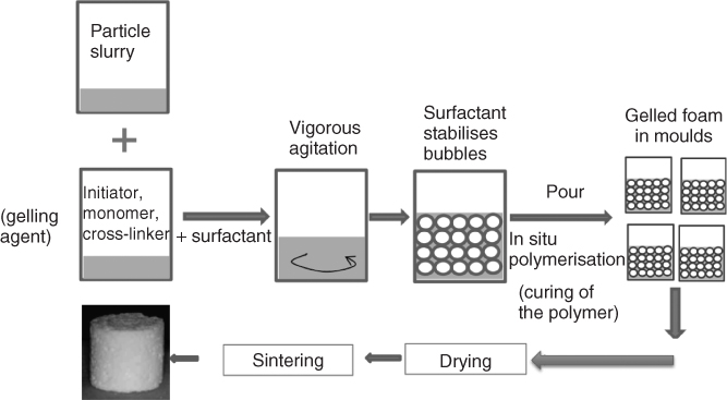
The pouring window is short: too early, and the foam cannot hold its own weight and will collapse; too late, and it will gel in the foaming vessel. The surfactant must be of suitable type and be homogeneously dispersed to obtain spherical pores. To obtain an interconnected pore network, the bubbles must be large and touching each other in the solution until gelation. On gelation, the surfactant films must rupture, opening up interconnecting channels between the bubbles, which now become the pores. After gelation, the foam is a composite of glass particles within the newly formed polymer matrix (Figure 12.9).
Figure 12.9 SEM images from the gel-cast foaming process of a bioactive glass after foaming and gelation of glass particles dispersed in a polymer foam: (a, b) low magnification; and (c, d) higher magnification, showing individual particles in the polymer matrix. (Images by Zoe Wu. Copyright (2012) Zoe Wu.)
In order to make the porous glass, the polymer has to be removed. Polymer removal and sintering occur in the same heat treatment procedure. The composite is usually held at around 300 °C to remove the polymer. At this point, the particles are effectively balancing on each other in the shape of a foam. As the temperature increases above Tg, the particles begin to sinter together. The sintering temperature depends on the sintering window of the glass composition being used, but is usually around 700 °C. A 3D image of a gel-cast foam scaffold can be seen in Figure 12.2. The scaffolds have large interconnecting pores without hollow struts. Figure 12.10 shows SEM images of a bioactive glass scaffold after sintering. Note the smoothness of the foam surface at higher magnification after sintering, which shows that sintering has run to completion. The amount of glass loading in the slurry is a critical factor in getting a good foam: too little glass means the particles are not in contact with each other, and the foam will slump before sintering can occur; and too much glass is difficult to foam. Particle size is also important: small particles sinter more easily as they have a higher surface area. However, as crystallisation of the glass is surface nucleating, a higher surface area also means crystallisation can occur at lower temperatures in smaller particles.
Figure 12.10 SEM images from the gel-cast foaming process of a bioactive glass after sintering: (a, b) low magnification; and (c, d) higher magnification. (Images by Zoe Wu. Copyright (2012) Zoe Wu.)
The gel-cast foaming process produces excellent scaffolds, but up-scaling for production is challenging. Another challenge is that, in order for a surfactant to function, water has to be present, so the glass has to be in a slurry of water. This means the glass will start to react with the water. Although the amount of time the glass is exposed to the water is short, it can trigger crystallisation of the glass to occur at a lower temperature.
The sol-gel process involves the hydrolysis of alkoxide precursors to create a sol (Chapter 3). The sol can be considered as a solution of silica species that undergo polycondensation to form silica nanoparticles, which then coalesce; further condensation links them together during gelation (under acidic catalysis). Calcium is usually incorporated using calcium nitrate. The gels are then dried and heated to at least 600 °C to remove the nitrates from the calcium nitrate. During the thermal processing, the coalesced nanoparticles sinter together, leaving interstitial nanoporosity. The nanopores are usually in the range of 1–20 nm diameter and can be tailored during processing by controlling the pH of the catalyst, the nominal composition and the final temperature. It is, however, difficult to produce large crack-free monoliths (greater than 10 mm thickness) because driving off the water, organics and nitrates causes capillary stresses that result in cracking.
Larger pieces can be made using the sol-gel foaming process, as the pores that are introduced reduce the distance that water molecules need to travel. To produce a porous glass, the sol is foamed under vigorous agitation (Figure 12.11). The viscosity of the sol increases until it becomes a solid gel, and therefore no polymeric gelation agent is needed. However, an extra catalyst is needed. Gelation normally takes around three days, and for a foaming process, a few minutes is needed. Hydrofluoric acid is the gelling agent of choice because, when gelation occurs, it occurs rapidly, allowing the porous foam to gel homogeneously.
Figure 12.11 Schematic of the sol-gel foaming process.

On gelation, the spherical bubbles become permanent in the gel. As drainage occurs in the foam struts, the gel shrinks and the bubbles merge, interconnects open up at the point of contact between neighbouring bubbles.
The sol-gel foam scaffolds have a hierarchical structure of interconnected macropores (Figure 12.2 and see Figure 14 in colour section), which mimic the porous structure of cancellous bone and allow the scaffold to act as a 3D template for tissue growth, and a nanoporosity that allows control of degradation (Figure 12.12).
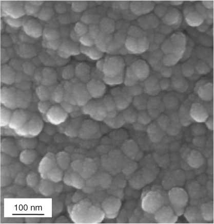
Figure 12.12 SEM image of the nanotopography of a 70S30C (70 mol% SiO2, 30 mol% CaO) sol-gel derived bioactive glass.
Cell response studies on the bioactive glass foam scaffolds have found that primary human osteoblasts lay down mineralised immature bone tissue, without the need for additional growth factors or hormones. Glass compositions are usually 58S (60 mol% SiO2, 26 mol% CaO and 4 mol% P2O5) or 70S30C (70 mol% SiO2, 30 mol% CaO). However, other network modifiers can be used for added functionality, such as strontium (anti-osteoporosis) or silver (antibacterial).
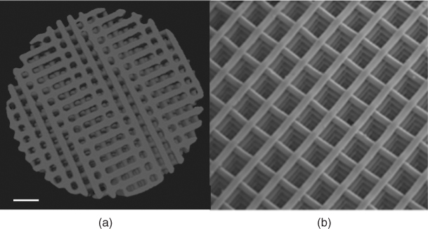
Solid freeform fabrication techniques are a collection of techniques that can build objects in almost any net shape, by depositing material layer by layer. The method is often also known as rapid prototyping. The advantage of these techniques over foaming is that the scaffold structure is dictated by a computer that controls the device that lays down the material. This means that scaffolds can theoretically be produced in any design as dictated by a computer-aided design (CAD) file. The CAD file could even be generated from a computer-assisted tomography (CAT) scan of a tissue, allowing complete replication of the structure of a tissue. However, in reality, not all materials can be used directly in solid freeform fabrication. Thanks to new melt-derived bioactive glass compositions, bioactive glass scaffolds are produced by a printing process called robocasting. The scaffolds produced had thick struts (>50 µm) and pores in excess of 500 µm (Figure 12.13 and see Figure 13 in colour section). The alignment of the rows of struts was so accurate that compressive strengths of more than 150 MPa were achieved in the direction of the pore channels (three times that perpendicular to the pore channel directions), with 60% porosity. This is similar to the strength of cortical bone. The composition used was 6P53B (51.9 mol% SiO2, 9.8 mol% Na2O, 1.8 mol% K2O, 15.0 mol% MgO, 19.0 mol% CaO, 2.5 mol% P2O5), with a particle size of D50 = 1.2 µm. Inks were created by mixing 30 vol% glass particles in 20 wt% Pluronic F-127 solution. Glass scaffolds were fabricated by extruding the inks through a 100 µm syringe nozzle using a robotic deposition device. The viscosity of the ink is critical. The inks were printed on an alumina substrate in a reservoir of non-wetting oil. The scaffolds were air-dried for 24 hours and subjected to a controlled heat treatment to decompose the organics and sinter the glass particles (700 °C).
Figure 12.13 Bioactive glass scaffolds produced by the robocasting solid freeform fabrication method: (a) X-ray microtomography image and (b) SEM image. (Image provided courtesy of E. Saiz and Q. Fu. Copyright (2012) E. Saiz and Q. Fu.)
Bioactive glass scaffolds have been synthesised with foam-like pore networks resembling the structure of cancellous bone. Compressive strengths of 2–15 MPa have been obtained in bioactive glass foam scaffolds while maintaining modal interconnect diameters above 100 µm (>80% porosity). Using solid freeform fabrication, higher compressive strengths were obtained (>150 MPa at 60% porosity), but the architecture was less similar to native bone. Although the compressive strength of glass scaffolds may be suitable for bone grafts in applications where the load is compressive and not cyclic, bioactive glass scaffolds suffer similar problems to other bioceramics: they are brittle. For certain applications, and to replace the need for autografts, improved toughness is needed.
Chapter 10 explains that bioactive glasses must be made more tough if they are to be used in sites that will be under cyclic loading. Chapter 9 showed that there have been several attempts to combine bioactive glasses with biodegradable polymers to create composite scaffolds with degradability, bioactivity and toughness. Chapter 10 discusses how conventional composites are flawed as synthetic bone grafts because the bioactive particles are generally covered by the polymer matrix. The host bone will therefore not come into contact with the glass. This may be rectified as the polymer phase begins to degrade and the glass is exposed. However, the polymer often degrades much more rapidly than the glass.
Sol-gel hybrids are different from composites in that the inorganic and organic components are interpenetrating networks that are indistinguishable above the sub-micrometre scale (Figures 10.1 and 12.14). Because the sol-gel process is initially at room temperature, polymers can be incorporated into the sol so that the polymer network is incorporated as the silica network forms. This nanoscale interaction can produce unique properties. Fine control of the degradation rate and mechanical properties can be achieved when covalent bonds are formed between the organic and inorganic chains (a class II hybrid, Figure 10.6).
Figure 12.14 Schematic of the structure of a sol-gel silica–organic hybrid.
Although the final processing temperature of the sol-gel hybrid process is lower (40–90 °C) than that of the sol-gel glass process (>600 °C), the foaming process can still be incorporated. However, there are complex chemistry challenges associated with this procedure, including which polymer to use and how to incorporate calcium.
Traditionally, calcium nitrate has been used as a precursor and donator of calcium into the inorganic network. However, temperatures of at least 600 °C are needed to drive off the nitrate by-products that are toxic to cells. The temperature must also reach 450 °C before calcium nitrate dissociates and calcium is incorporated into the network. Hybrids cannot be heated to high temperatures, as the polymer will be damaged. Therefore, another calcium precursor is needed.
Many bioresorbable polymers, for example, poly(lactides), cannot be simply introduced into the sol, as they are not soluble in the sol. However, they can be functionalised so that not only are they incorporated in the sol-gel process, but also they can form covalent bonds with the silica network, creating a class II hybrid material. The functionalisation of the polymer involves the introduction of coupling agents.
One example is silica–poly(ε-caprolactone) (PCL) hybrids. Hydroxyl groups at either end of poly(ε-caprolactone diol) polymer chains can be reacted with 3-isocyanatopropyl triethoxysilane (IPTS). This process results in a polymer end-capped with a triethoxysilyl group. When the end-capped PCL is introduced into a sol, the siloxane groups hydrolyse and then Si–OH groups from the end-capped polymer condense with the Si–OH groups from the hydrolysed TEOS in the sol to yield an interconnected PCL–silica network.
Alternatives to conventional polyesters are natural polymers, which can be a closer mimic of bone's natural structure. Bone contains collagen, which is a structural protein with a triple helix of polypeptides (amino acid chains), giving it excellent mechanical strength (the structure is analogous to that of rope).
Collagen would therefore be an ideal choice to use as a natural polymer in hybrid synthesis. Unfortunately, the triple helix structure makes it very insoluble. It will dissolve in acetic acid, but only in very low concentrations. Therefore, it is not possible to produce a hybrid with significant amounts of polymer using collagen. Where to source the collagen is also an issue. Currently, it cannot be synthesised in any significant quantity, so it must be sourced from animals. Although collagen is unlikely to be rejected by a patient's body, patients may refuse an implant on religious or moral grounds owing to the animal species from which it originates, for example, bovine (cow) or porcine (pig).
One of the great benefits of natural polypeptides is that they can be functionalised. Gelatin has great potential as it is hydrolysed collagen and it is water-soluble. It also contains –COOH groups (carboxylic acid), –NH and –NH2 groups along its backbone that are available for functionalisation. This time, glycidoxypropyl trimethoxysilane (GPTMS) is used as the coupling agent. The glycidol group (expoxy ring) can open and react with the functional groups on the polymer chain. The functionalised polymer has short molecules bonded to it with Si–OH groups on the end of them, ready to undergo condensation with other Si–OH groups from the silica in the sol, to form Si–O–Si bonds. Any polypeptide can be functionalised and incorporated. An example is poly(γ-glutamic acid) (γ-PGA), which is a much simpler polypeptide than gelatin; γ-PGA is synthesised by a biotechnology route, that is, produced by bacteria.
Another popular natural polymer is chitosan, a polysaccharide derived from crustacean shells, which contains –OH and –NH2 groups.
Class II hybrids of silica–gelatin, silica–γ-PGA and silica–chitosan have been produced with several methods of adding calcium. They have also been foamed to produce porous scaffolds (Figure 12.15). A schematic of the process is shown in Figure 12.16. In some processes, drying is carried out at low temperatures; in others, (preferably) freeze drying quickly removes the water and other by-products of condensation. Scaffolds can be made with stiffnesses ranging from that of a polymer to that of a glass, or anywhere in between, by controlling the percentage of organic and the degree of covalent coupling. Importantly, release of the polymers can be coupled to the degradation of the silica, meaning that the materials degrade as one material, or true hybrids. The future may well be the use of human recombinant proteins, but much development is needed to increase their yields.
Figure 12.15 Three-dimensional X-ray microtomography image of a sol-gel foam hybrid. (Image by Sheng Yue. Copyright (2012) Sheng Yue.)
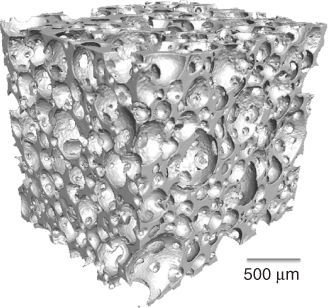
Figure 12.16 A schematic of the sol-gel foaming process for hybrids.

Tissue engineering is the regeneration of tissues through the combination of engineering and biology principles. A common strategy for bone tissue engineering is to use a scaffold as a temporary template for cells to produce new tissue. The main difference between tissue engineering and a synthetic bone graft that regenerates bone is that tissue engineering is partly done in a laboratory. A scaffold can be seeded with cells in a laboratory and encouraged to grow on the scaffold. The cells must penetrate the scaffold, attach and produce bone matrix. A choice has to be made as to the point at which the construct is implanted: it could be implanted immediately after the cells are seeded; after a specified time; or once an entire tissue has been grown and the scaffold degraded, so only tissue is implanted. Ideal tissue engineering would be growing entire replacement parts (organs) so that they are ready for use, using a patient's own cells to prevent rejection. This has only so far been achieved with skin, using polymer scaffolds, but the skin produced does not contain many of the components of natural skin, for example, sweat glands, pores, pigment cells and hair follicles. A big advantage of growing a large piece of tissue and allowing the scaffold to degrade is that the surgeon will not be implanting any synthetic material, so some of the regulatory issues for medical devices can be avoided.
In reality, though, bone is such a complicated structure that needs a combination of different cells, growth factors and mechanical stimuli. The process of bone production is so complicated that it seems the only way to achieve it would be to use the body as its own bioreactor. That is not to say that tissue engineering does not have potential. When large porous constructs are implanted, a limiting factor can be that blood vessels do not penetrate, even if the scaffold is bioactive and stimulating bone growth. Bone needs blood vessels if it is to survive, but also blood vessels will not grow into a porous construct if there is no living tissue inside it. This creates a bit of a ‘chicken and egg’ or ‘Catch 22’ situation, to which tissue engineering may be the answer. Stem cells could be grown in the pores of the scaffold in the laboratory prior to implantation so that, when the construct is implanted, there will already be viable cells present. The cell source has to be carefully considered. Perhaps an ideal cell source would be bone marrow stem cells from the patient. Bone marrow stem cells are thought to be those responsible for natural bone repair, where they differentiate into bone-producing cells (osteoblasts). Harvesting them from the patient is relatively straightforward compared to some other cell types, although the numbers that can be obtained are low. The aim would be to seed them within the scaffold and hope they attach and proliferate, and that the scaffold stimulates them to become bone cells rather than another cell type, such a cartilage cell or fibroblast.
Alternatively, blood vessels could be grown inside the scaffold in the laboratory, with the aim that they will connect up with existing vasculature. This strategy has been proven to work in mice.
Bone tissue engineering is not in widespread clinical use, unless you count mixing blood from the patient with a scaffold.
Once a promising new scaffold material has been developed and tested in the laboratory with cell culture tests and long-term mechanical tests as a function of degradation, it is time to translate the work from the bench to the bedside. This is not a trivial (or inexpensive) process. It takes considerable time and investment. Difficult decisions also have to be made. An important early decision is the class of material for which regulatory approval should be sought. At the time of writing, regulatory bodies, such as the FDA and the EU, are (quite rightly) making regulatory approval more difficult to achieve. Although it may disadvantage new companies with potentially important new products, safety must be paramount. The regulatory class depends on the claims made by a company. For example, in the EU, if a company claims that a scaffold will bond to bone, degrade over time and stimulate bone regeneration, it will be a Class 3 medical device. If the company claims a new material will simply do the same as other bone grafts and fill space, it will be a Class 2 device, but then the marketing or sales people in the company cannot claim performance superior to current products. Of course, to obtain regulatory approval of a Class 3 device takes more investment and may involve lengthy clinical trials. Claiming pharmaceutical properties of an implant may also mean that approval is needed from pharmaceutical (rather than device) regulatory bodies such as the UK Healthcare Products Regulatory Agency (MHRA).
Bioactive glass foam scaffolds have the potential to improve performance of bioceramic bone grafts, but no bioceramics will ever fulfil all the criteria for an ideal scaffold. Inorganic–organic hybrids have the potential to be tough bioactive and biodegradable scaffolds. A massive challenge is expanding this technology to regenerate load-bearing skeletal components such as the hip. Replacing metals as load-bearing devices is the ultimate, but perhaps unachievable, goal. Tissue engineering approaches are not yet widely used in the clinic, except that surgeons often mix blood and bone marrow with implants, hoping to activate some stem cells already belonging to the patient. Incorporating osteoprogenitor cells within scaffolds may be the best solution if healthy bone is to be achieved in large defects.
Porous Bioceramics
Hing, K.A., Revell, P.A., Smith, N., and Buckland, T. (2006) Effect of silicon level on rate, quality and progression of bone healing within silicate-substituted porous hydroxyapatite scaffolds. Biomaterials, 27, 5014–5026.
Jones, J.R. and Hench, L.L. (2003) Regeneration of trabecular bone using porous ceramics. Current Opinion in Solid State and Materials Science, 7, 301–307.
Sepulveda, P., Binner, J.G.P., Rogero, S.O. et al. (2000) Production of porous hydroxyapatite by the gel-casting of foams and cytotoxic evaluation. Journal of Biomedical Materials Research, 50, 27–34.
Porous Melt-Derived Glasses
Elgayar, I., Aliev, A.E., Boccaccini, A.R., and Hill, R.G. (2005) Structural analysis of bioactive glasses. Journal of Non-Crystalline Solids, 351, 173–183.
Fu, Q., Rahaman, M.N., Bal, B.S. et al. (2008) Mechanical and in vitro performance of 13-93 bioactive glass scaffolds prepared by a polymer foam replication technique. Acta Biomaterialia, 4, 1854–1864.
Fu, Q., Saiz, E., and Tomsia, A.P. (2011) Bioinspired strong and highly porous glass scaffolds. Advanced Functional Materials, 21, 1058–1063.
Wu, Z.Y., Hill, R.G., Yue, S. et al. (2011) Melt-derived bioactive glass scaffolds by gel-cast foaming technique. Acta Biomaterialia, 7, 1807–1816.
Sol-Gel Foaming
Gough, J.E., Jones, J.R., and Hench, L.L. (2004) Nodule formation and mineralisation of human primary osteoblasts cultured on a porous bioactive glass scaffold. Biomaterials, 25, 2039–2046.
Jones, J.R., Ehrenfried, L.M., and Hench, L.L. (2006) Optimising bioactive glass scaffolds for bone tissue engineering. Biomaterials, 27, 964–973.
Jones, J.R., Tsigkou, O., Coates, E.E. et al. (2007) Extracellular matrix formation and mineralization on a phosphate-free porous bioactive glass scaffold using primary human osteoblast (HOB) cells. Biomaterials, 28, 1653–1663.
Sepulveda, P., Jones, J.R., and Hench, L.L. (2002) Bioactive sol-gel foams for tissue repair. Journal of Biomedical Materials Research, 59, 340–348.
Porous Hybrids
Mahony, O., Tsigkou, O., Ionescu, C. et al. (2010) Silica–gelatin hybrids with tailorable degradation and mechanical properties for tissue regeneration. Advanced Functional Materials, 20, 3835–3845.
Poologasundarampillai, G., Ionescu, C., Tsigkou, O. et al. (2010) Synthesis of bioactive class II poly(glutamic acid)/silica hybrids for bone tissue regeneration. Journal of Materials Chemistry, 40, 8952–8961.
Valliant, E.M. and Jones, J.R. (2011) Towards softer materials for synthetic bone graft applications: hybrid materials. Soft Matter, 7, 5083–5095.
Tissue Engineering of Blood Vessels Inside Scaffolds
Tsigkou, O., Pomerantseva, I., Spencer, J.A. et al. (2010) Engineered vascularized bone grafts. Proceedings of the National Academy of Sciences, 107, 3311–3316.