Chapter • 13
Compound Miter for Dummies
BY NICK ENGLER
Well, this is embarrassing, I thought to myself. Steve, Tricia and Al — a large part of the Pop Wood team — had made a pilgrimage to my shop to take photos of an expert craftsman making flawless compound miter cuts. And I couldn’t remember how to do it.
“Wait just a minute,” I told them. “I’ve got a book right here that tells what to do.” I reached for a copy of “Nick Engler’s Woodworking Wisdom” and read my own instructions on the technique.
Making compound miters — a miter joint that is both angled and beveled — is one of those special techniques that most woodworkers need only once in a great while. It’s a neat trick with intriguing results. When you join the frame members, the boards have a slope so the assembled shape tapers from one edge to the other. You can employ compound miters to make picture frames, bowls, pedestals and dozens of other projects such as the Two Tub Tables on the following pages. Trouble is, it’s not a technique you’re likely to use every day, or even every month. In between the times when you need it, you’re likely to forget some of the finer points — I know I do. So I’m going to write this article as a “refresher course” in compound mitering, as much for myself as all of you.
Figuring the Angles
When cutting a compound miter on a table saw, you must set both the miter angle of the miter gauge and the bevel angle of the saw blade. These angles depend on two things — the number of sides in your frame and the slope of the assembled frame. The slope, by the way, is usually measured from horizontal, with the frame resting on a flat surface.
For every frame and slope, there is just one pair of angles, and these angles must be precise or the miter joints will gap. To find these angles, woodworkers of yore went through a convoluted drafting process that takes two days just to explain. Contemporary craftsmen either use some simple equations or they refer to a compound miter chart. I prefer the chart method myself, so I’ve included one with this article that lists angle pairs for lots of frame assemblies and slopes. But just in case you don’t see the angle settings you need for your particular project, here are the equations:
Miter Angle (for all joints): tanMA = 1 ÷ [cosS × tan(360 ÷ 2N)]
Bevel Angle (for mitered joints): tanBA = cosMA × tanS
Bevel Angle (for butted joints): tanBA = cosMA ÷ tanS
Where: MA is the miter angle; BA is the blade angle; S is the slope; N is the number of sides.
If you’re mathematically challenged, don’t despair at the mention of tangents and cosines. I too slept through high school trigonometry. But I still work a trig equation now and then by pounding on a scientific calculator. These have special buttons marked sin, cos and tan to simplify the functions — trigonometry for dummies.
For example, if you want to figure the miter angle for a four-sided mitered frame with a 30-degree slope, find the cosine of the slope by entering 30 on the keypad and then pushing the cos button. The result should be 0.8660 and change. Next, multiply the number of sides (4) by 2 and divide the result (8) into 360 — the result is 45. Find the tangent of 45 — that’s right, just push the tan button on the calculator. Multiply the result (1) times 0.8660, then divide that number (0.8660) into 1. The answer is 1.1547 — that’s the tangent of the miter angle. To convert this tangent into an angle, press the INV (or “inverse”) calculator button, then the tan button. Your miter angle is 49.1074 degrees.
Always figure the miter angle first, then the bevel angle. You need the cosine of the miter angle to calculate the bevel. Note that the bevel angle equation is slightly different depending on whether you want to make the joint mitered (with the seam at the corner) or butted (with the seam visible on one side).

To check your setup, cut enough small pieces to make a complete frame. Clamp a stop to the miter gauge extension so each piece is identical.

On the chart, I’ve rounded the angles to two decimal places. There probably isn’t a table saw on the planet that can measure hundredths of a degree, let alone the eight decimal places you’re likely to get from your calculator. But this will help you guesstimate where to set the pointer between two degree marks on the miter gauge scale and the blade tilt scale.
Cutting the Angles
Now for the easy part — and the part I always forget. Once you’ve set the miter and bevel angles, there’s a nifty trick for cutting both the right and left miters on the frame members without having to change settings. It’s all in how you flip the board.
I prefer to cut compound miters with a long miter gauge extension (a board fastened to the face of the miter gauge) that extends well past the blade. This not only provides better support, it gives you a surface to fasten a stop so you can make precise duplicate parts.
To make the first cut, place the board against the miter gauge extension and feed it into the blade, cutting through both the board and the extension. Flip the board edge for edge, so another edge rests against the extension and another face rests against the table. The board ends should remain oriented as they were. Position the board for the second cut and feed it into the blade. If the second cut is near the end of the board, and there isn’t enough wood for you to hold it safely against the extension, move the miter gauge to the other slot on the opposite side of the saw blade. You won’t need to change the settings.
Adjusting the Angles
Before cutting good wood, it’s always a good idea to make some test cuts to check your setup. I cut enough small identical pieces to make one frame, then assemble it with masking tape to check the joints. If the settings are off, one of the compound miter joints will gap. When the gap opens to the outside of the frame, increase the bevel angle. When it opens to the inside, decrease the angle. This may change the slope very slightly, but usually not enough to notice.

Here’s the compound miter technique in a nutshell. Angle the miter gauge, tilt the blade, make your first cut, flip the board edge for edge, and make the second cut. You’d think I could remember that.
Assembling the Frame
The best clamps I’ve found for gluing up compound miters are band clamps. If the slope is fairly steep, wrap the band clamps around the corners of the frame as you would when assembling a box. As the slope becomes shallower, however, the clamps tend to slip up the slope. When this is the case, wrap the clamps around edges of the assembled frame members, like the ribbons on a Christmas present. Be careful not to overtighten the clamps or the frame members will bow. If you can’t get enough clamping pressure without bowing, use additional band clamps and position them as close to the corners as possible. Control the bowing by wedging a scrap between opposite members to act as a temporary brace.
In some compound miter assemblies with multiple sides, I’ve seen craftsmen put the members together in several steps. They assemble two halves, then sand or joint the adjoining surfaces of the halves for a tight fit, and glue the halves together. This is commonly done when gluing up blanks for lathe turnings where the strength of the glue joints are critical and even the tiniest gap in a joint could spell disaster when the stock is spinning at a high speed.

To calculate compound miter angles, you need a scientific calculator (about $12 at most office supply stores) with SIN, COS, TAN, and INV buttons. On some calculators, the INV button is labeled FUNC for “function.” If you have a computer and use Microsoft Excel software, you can download a simple Compound Miter Calculator that I wrote from the Pop Wood web site: www.popwood.com
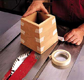
Tape the pieces together at the corners and inspect the joints. If you find any gaps, adjust the bevel angle in tiny increments and cut new test pieces until the gaps disappear.
Compound Miter Chart for the Table Saw
