Chapter • 14
The Case for Case Miters
BY BILL HYLTON
What joint would you use at the corners of a case? If appearance is a consideration – when is it not? – you definitely don’t want an ugly joint like a rabbet. No matter how thin, that strip of exposed end grain – the butt of the board – is unattractive.
From the standpoint of what looks best, the miter joint should be atop your list. The only surfaces visible are the attractive ones: the faces and the edges. If you are making a small chest and you have a wide, long board with killer figure, you can wrap that figure around the corners without interruption.
You may think of the case miter as being difficult in subtle ways. Well, yes, it can be. If the joinery cuts are off by a degree or two, the joint isn’t going to be square no matter what you do. Gluing and clamping the parts can be an exercise in torment and despair. There’s no mechanical interlock to hold the parts in alignment, and glue just enhances the natural tendency of the surfaces to creep.
Moreover, despite the fact that a miter joint has more gluing surface than a butt joint, the glued miter joint isn’t that strong. The shortcoming is that the miter brings end grain to the glue-up session.
But simple solutions to these and other difficulties do exist, and the results make it a joint worth mastering.

Try this with a garden-variety case miter joint. The lock miter joints hold your parts together on their own, freeing both your hands to apply clamps.
Case Miter Varieties
Let’s look first at some of the ways the joint can be shaped to reinforce it, and to make assembly and clamping easier and more effective. The most basic miter joint is made by beveling the mating edges of both parts at 45°, then butting these edges together.
Surely the easiest way to make the joint simpler to align is by using biscuits. If you have a biscuit joiner, you know it takes only a minute to set the fence and cut slots in both parts. The biscuits make alignment easy and they offer some reinforcement to the joint as well.
Lacking a biscuit joiner, you can achieve the same effect with a through or stopped spline. The details of how to cut a slot and fit a spline were covered in the October 2003 issue (available for sale online at popwood.com), so I won’t repeat that here.
Another joint worth learning to master is a routed lock miter joint because it gives the appearance of a miter but introduces an interlock, expands the glue area and makes assembly and clamping foolproof. We’ll come back to that in a little while.
Sawing the Bevels
Accurate 45° bevels on the mating parts are essential for the case miter. You could cut the bevels using a radial-arm saw, compound-miter saw or sliding compound-miter saw. But the capacity of the latter two saws is limited, typically less than 12”, and all three saws can have some accuracy shortcomings.
You’ll most likely want to cut the bevels on a table saw. Tilt the blade to 45° and, depending on the proportions of your workpiece, guide the work through the saw with the miter gauge or along the rip fence. It’s pretty cut and dry, until you run into one (or more) of the problems that often come up.
First of all, be wary of kickback. If you’re using the rip fence, you always want the saw blade to tilt away from it. With the blade tilted toward the fence, the offcut is trapped between the blade and the fence, and it’s all but certain to fire back toward you.
If you have a left-tilt saw, the customary fence location (to the right of the blade) is the safe one for bevels. But most saws are right-tilters, and with those saws the fence will have to be moved to the left of the blade. In any event, be sure you stand to the left of the blade, clear of “Kickback Alley.”

A backup strip attached to the miter gauge aids when you are trying to locate the bevel cut. Align your layout line with the kerf in the strip.

A sure way to assemble case miters is with shop-made miter-clamping cauls. Clamp a caul to each half of the joint, then apply clamps. Do one joint at a time.
The most disheartening problem is the one that isn’t evident until all the joints are cut and you start assembling them. This is when you discover that the bevel angle is off a degree or two, and the joints aren’t square. Maybe you didn’t tilt the blade enough, but more likely the fault is hiding in the adjustment and alignment of the saw.
You should know if you can trust the scale on your saw when you tilt the blade for this cut. If you aren’t absolutely certain it is accurate, use a drafting triangle to check the blade’s angle. Crank the blade to its maximum height, tilt it, then check it. Make sure the triangle is flat against the saw blade’s body and not against a carbide tip.
Double-check the angle by making a pair of test cuts and join the two samples. If the corner they form is square, your setup is right and you can proceed.
You won’t always use the rip fence. If the edge being beveled is the short one, you’ll want to use the miter gauge. This common accessory is, of course, another source of inaccuracies. If you use your miter gauge, make sure you square it to the blade with a drafting triangle before tilting the blade.
Instead of a miter gauge, a lot of us use a crosscut sled to ensure we get square cuts. The sled can be used for bevels, too.
If you make a lot of bevel cuts and think it’s worth the materials and shop time, you can make a sled exclusively for bevel cuts. If you do this, you’ll derive a couple of benefits. One is the unmistakable angled kerf you can use to align the workpiece. Another is the zero-clearance around the kerf, which helps minimize chipping on the underside of the workpiece. If you work with veneered or melamine-coated sheets, this is a benefit you’ll really appreciate.
Finally, if you are using a contractor’s saw, you may be reluctant to tilt the blade at all. Doing that can throw some saws out of alignment. Instead of tilting the blade, you can use an angle sled to deliver the work to the blade. In this case, the workpiece is tilted instead of the blade.
Aligning the work for the cut is less straightforward than you might think. If you’re using the crosscut sled or a miter gauge with a backup strip, you have a kerf to use.
But there’s no practical way to measure directly from the tilted blade to position the fence. Instead, you have to lay out the bevel cut on the stock and align the layout line with the blade. Then bring the fence into position. It’s easy to do this with your stock on the outfeed side of the blade.
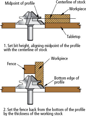
SETTING UP A LOCK MITER BIT
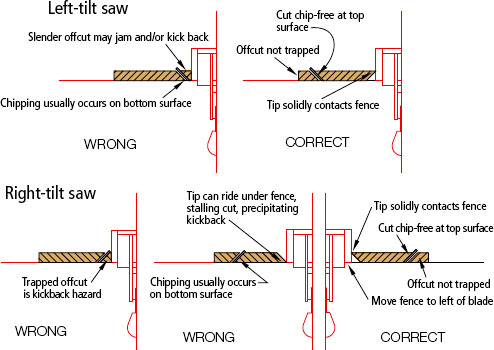
POSITIONING A RIP FENCE FOR BEVEL CUTS
Assembly
The biggest problem you will confront when assembling a case miter is applying clamp pressure without forcing the joints out of alignment. V-blocks, lined with packing tape to shed glue, can hold the tips of the bevels together, but other strategies work, too.

Adjust the lock miter bit up or down based on your test cuts. Halve the sample and fit the resulting two pieces together to see how they fit.

Half of each lock miter joint is cut with the work flat on the top of the router table. Using a push block helps you hold the workpiece down while you advance it across the bit.

Stand the work on end flat against the fence to rout the other half of the joint. A featherboard keeps the workpiece against the fence, obviating the need for a tall fence facing.
Glue tack often holds a small box together while you position pressure blocks and apply clamps. Or you can use packing tape to hold the parts while you apply the clamps. Tape the outside of the joint before adding glue.
With a chest or cabinet, the parts are larger, more cumbersome and less cooperative. In this situation, it may be practical to address one joint at a time. Glue up two joints individually, then wait for the glue to set before combining them into the box or case.
Also, adding biscuits or splines to the joint makes it easier to align and hold the pieces in place while you position the blocks and apply the clamps.
Lock Miter Joint
The routed lock miter sets off in a very different construction direction. You get that attractive miter-joint appearance, but you use a table-mounted router and a “trick” bit to cut it. When the time comes for assembly, the joint aligns perfectly and you can apply clamps without pressure blocks.
The bit’s trick is that one setup suffices for cuts on both pieces you want joined. When you have the bit adjusted spot-on and the fence perfectly positioned, you’re golden. Just lay one panel flat on the tabletop and slide it along the fence to rout it. Stand the mating panel upright against the fence to make the mating cut on it.
There are two parts to the setup process: setting the bit height and then setting the fence position. You have to make gross settings of both before cutting anything. Then, through a series of test cuts, you hone in on the optimum settings, first of the bit height, then of the fence position. Here’s how:
• Setting the Bit Height: The key is lining up the midpoint of the bit with the center of the stock. The midpoint of the bit is on the very slightly angled edge of the interlock, as shown in the illustration below.
The best thing you can do is mark the centerline on a scrap piece of the working stock, set it beside the bit, hunker down and squint across the tabletop to line them up. Maybe you’ll nail the alignment, but it’ll probably take a test cut and an adjustment (or two) to get it just right.
Having set an approximate bit height, move the fence into position to guide your first test cut. I stand a piece of the working stock “behind” the bit and sight along the fence to the bit. My objective is to have the stock aligned with the profile’s bottom edge.
Make a test cut with the sample flat on the table. Cut it in half, turn one of the pieces over and join the two. If the faces are flush, the bit setting is perfect. If they are offset, an adjustment is needed, as shown below.
Use the depth-bar of a dial caliper to measure the offset between the two test pieces. Raise or lower the bit half the measurement. (Having a good depth-adjustment system on your router and table is a boon here.)
• Setting the Fence: When cutting the joint, you’re dealing with a 45° bevel. The exposure of the cutting edge above the table and in front of the fence must match the thickness of the working stock. Because the bit is set, it’s no longer a variable. Only the fence position is in play. If the fence is set too far back, a cut will remove too much stock and alter the length or width of the workpiece. If it is too far forward, you won’t get the full miter. You already have a gross setting; now you just need to refine it.
To set your fence correctly, cut a scrap piece from the working stock, feeding only a few inches into the cut.
• If the tip is square, move the fence back to expose more of the bit.
• If the cut is shortening the material, pull the fence forward so that it will be able to house more of the bit.
• If the tip comes to an acute angle whose tip is flush with the square, unrouted edge of the stock, the fence position is just right.
With the final fence position set, you can proceed to the real workpieces.