Chapter • 21
Variable Spaced Dovetails
BY DON MEANS

Some of us just don’t have the time, patience or skill to produce hand-cut dovetail joints and instead resort to one of the numerous dovetail jigs available on the market. However, at several hundred dollars apiece, not everyone can justify the expense of a variable-space jig, such as the Leigh D4R. Even if you do happen to own this fine jig, for certain applications I find it easier and more efficient to use a simpler jig. For example, when building cabinets or furniture for my workshop I usually don’t want to spend the time setting up my Leigh D4 (yes, I do own one). However, I still want the dovetail joinery to have aesthetic appeal.
I’ve experimented with a number of dovetail router bit sizes and cutting angles and, using a basic fixed-finger dovetail jig, have refined two techniques that greatly improve the overall aesthetics of the resulting half-blind dovetail joint. In addition, with a bit of planning, and within certain limitations, it is even possible to create “variable-spaced” half-blind dovetails with this “fixed-finger” jig.
Dovetail Jig Geometry
In order to fully utilize these techniques, it is helpful to have an understanding of the geometry surrounding the dovetail joint produced by the fixed-finger jig. Although jigs of this type generally operate the same way (that is, the pins and tails are produced in a single operation) not all of them have the same geometric characteristics. For example, the Porter-Cable and Hartville jigs are similar, while jigs by Rockler, Jet and Woodtek have slightly different characteristics. For this article, I worked with the Porter-Cable 4112 dovetail jig equipped with a ½” half-blind dovetailing template. However, it should be possible to apply this technique to just about any fixed-finger dovetail jig, once you understand the basic geometric relationships.
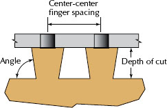
When using a fixed-finger jig, the dovetail bit diameter and center-to-center finger spacing are the critical dimensions that control the geometry of the dovetail joint. The key geometric relationship for the joint is the amount of overlap or interference between the tail and the pin.
This relationship is determined by (1) the center-to-center finger spacing, and (2) the diameter of the dovetail cutter. The slope or angle of the dovetail bit is secondary to this relationship. In fact, this is what we are going to “play with” in order to improve the appearance of the joint.
Adjusting the depth of cut determines the amount of interference between the tail and pin, and determines the fit of the joint. As the angle of the dovetail bit is reduced, it is necessary to increase the depth of cut in order to maintain the proper tail/pin interference. This reduced or slighter angle, as well as the increase in the depth, is the key to improving the appearance of the joint.
For these types of fixed-finger jigs, the relationship between center-to-center finger spacing, cutter angle, diameter and, ultimately, cutter depth is defined by the following formula:
Depth of Cut = {D-S/2} ÷ Tangent(a)
where:
D = dovetail bit diameter
S = dovetail jig center-to-center finger spacing
a =cutter angle (in radians)
CRITICAL DOVETAIL DIMENSIONS
This formula provides the insight we are seeking. As you can see, for a given cutter diameter and finger spacing, the cutter angle is inversely proportional to the depth of cut. As the cutter angle is decreased the depth of cut must increase.
This formula might be the end of our minor math lesson if we were cutting dovetails in metal with a precision CNC mill. Unfortunately, we are cutting with tools that have a variety of associated built-in errors (router and bit run-out, bushing and template fit and bushing/router eccentricity, to name a few). All these factors result in an effective increase in the diameter of the cutter.
A ½” cutter will tend to act like a slightly larger bit. With my equipment (the PC jig and a DeWalt 621 router) I found through trial and error that all of these imperfections added about .010” to the bit diameter. In other words, a 0.500”-diameter router bit acts like a 0.510”-diameter bit. This effective diameter should be used to calculate the estimated depth of cut provided in the preceding formula. (Note: Everyone’s tools are slightly different so you will have to experiment to find the amount of variation in your setup.)
Planning the Width (Plus or Minus)
For the majority of applications, the most aesthetic arrangement for half-blind dovetails is to end with a half-pin at the upper and lower edge of the drawer side (or tail board). Unfortunately, when using a fixed-finger dovetail jig this requires the side of the drawer to be limited to certain widths. Some planning is necessary to ensure the joint ends on a half-pin. The Porter-Cable 4112 has a center-to-center finger spacing of 7⁄8” so in theory, drawer side widths have to be multiples of this dimension.
Creating a Variable-spaced Dovetail Joint With a Fixed-finger Jig

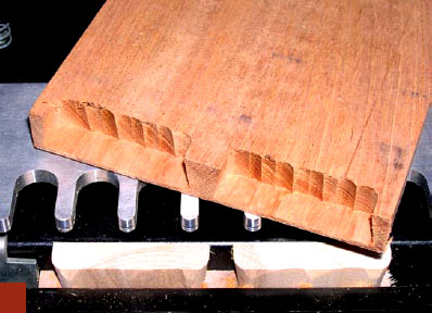
ROUGH CUT THE TAILS. With the jig and depth of cut properly set, first take a back cut along the width of the drawer side. Then, as you normally would, start at the inboard end of the jig and rout out the first tail socket. However, do not rout the next slot in the jig template. Instead skip over the next two slots to the fourth slot. Rout out this tail socket, then again skip the next two slots and finish up on the last slot (which should be the outside edge of the drawer side). As you look at the drawer front there should only be two tail sockets routed in the drawer front (or pin board) and two “wide” tails that are roughly defined on the drawer side.
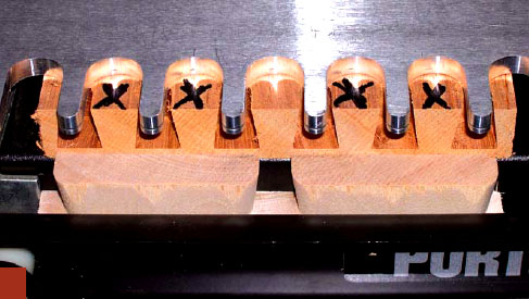
FINISH THE TAIL SOCKETS. The next several steps in the procedure require you pay close attention to your work. Basically, we are going to manipulate the drawer front in the jig to hog out the unneeded pins in order to create two wide sockets for the wide tails we just milled.
First, unclamp the drawer front and slide it toward the outboard side of the jig (to the right as you are facing the jig) exactly half the finger spacing (do not unclamp the drawer side). At this stage the edges of the drawer front and sides should be aligned and it should become obvious which pins will be removed to create the wide sockets for the tails that were previously cut.
Use the drawer side as a reference to square up the drawer front by pushing it up against the tails and re-clamp. At this point, there should be no tail sockets showing (in other words, all you should see are the individual pins). For this particular dovetail layout, unneeded pins will be removed using the second, third, fifth and sixth template “slots” (notice we skipped the fourth slot since this pin is aligned with the pin socket from the tail cutting operation). These steps in the procedure can get confusing if you are not careful. The safest strategy is to use a pen to mark the areas that are to be removed.
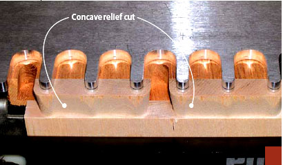
FINISH THE TAILS. Next it is necessary to “finish” the tails by carefully removing the material on the back (or inside) of each of the tails. This is necessary to ensure the proper fit of the joint. Start at the left-hand side of the jig and carefully move the router from left to right between the template fingers, slightly “dipping” between the template fingers. (It is not necessary that this be a perfectly straight cut since it will be hidden in the assembled joint.)
I usually make this cut slightly concave – just to ensure there will be no interference with the tail socket. Make sure you do not remove too much material as this will begin to affect the strength of the joint (obviously if you cut all the way through the tail you will have ruined the piece).
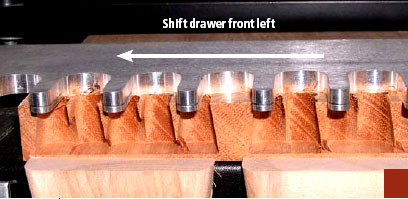
ROUT BETWEEN THE FINGERS. Once the drawer front is marked and secure in the jig, rout out the marked areas between the template fingers. After this is complete you should be left with very thin sections of the former pins. Now unclamp the drawer front and slide it toward the inboard end of the jig (to the left) until these thin sections are centered in the template finger slots. As before, use the drawer side as a reference to square up the drawer front.
Clamp the drawer front and hog out the marked sections. At this point it should begin to become obvious how we are manipulating the jig to produce the wide tail sockets. Once this is done, unclamp the drawer front, slide the piece in the opposite direction (to the right) until the remaining thin sections are centered in the template slots (again use the secured drawer side as a reference to square the drawer front in the jig) and repeat the cutting procedure.

ROUGH CUT THE TAIL SOCKETS. Once the drawer side is complete we turn our attention to the drawer front (or pin board). First, unclamp the drawer side and lower it so the top of the tails are just below the tail sockets on the drawer front and then re-clamp (this is so the router bit will clear the top of the tails when cutting the tail sockets). Now rout out all of the tail sockets as you normally would.
READY TO ASSEMBLE. If you performed these last several steps correctly when you remove the drawer front from the jig you will see two wide tail sockets that should perfectly match up to the wide tails previously cut. The joint is now complete and ready to be assembled.
But it isn’t necessary that the half-pins be exactly one-half the pin width. A typical ½”-dovetail cutter will produce a throat width that is approximately 3⁄8” (therefore the half-pin throat width would be about  ”). As long as you are close to this dimension (±
  ” at most) the joint will look OK. Because there are two half-pins on each drawer side this allows a total variation of ± ⅛” over the drawer side. The chart below lists the possible sizes under this parameter.
Most moderately priced dovetail jigs include a basic ½” diameter, 14º dovetailing bit. Under normal operation these cutters produce a “stubby” dovetail joint, with tails approximately 5⁄16” long. In addition, the 14º angle of the tail is not very graceful.
Drawer Side Width*

* Note: This chart provides the typical drawer side widths that are possible when using the PC 4112 dovetail jig and similar jigs with equivalent finger spacing. When properly set up in the dovetail jig, these widths will result in a half-pin at each end of the drawer.
Commercially Available Dovetail Bits That Can Be Used in Fixed-Finger Jigs

Although there are a variety of dovetail cutters on the market, only a few have the proper cutting geometry that will allow them to work with the typical fixed-finger jig.See the chart below for cutters I have found that work with this technique.
A Simple Improvement
A basic improvement when using the fixed-finger jig is to simply substitute a ½”-diameter, 8º cutter (such as the #80 bit for the Leigh jig) for the standard cutter. Set up the jig as you normally would by following the manufacturer’s instructions. The only change to the normal setup is the depth of cut – which should be set to about 25⁄32”. The actual length of the tail will be about 17⁄32”. However, when measuring the cutter depth from the base of the router, it is necessary to take into account the thickness of the finger plate (1⁄4” in this case).
It will probably be necessary to fine-tune the depth of cut by experimenting with some scraps of wood. Simply follow the jig maker’s instructions for making these adjustments.
Once you have fine-tuned the settings, you are ready to dovetail the final pieces. I like to back (or climb) cut the inside edge of the tails to create a clean inside edge for the pin sockets. Proceed to cut the pins and tails as you normally would, then assemble the joint. The longer tailed, slighter-angled dovetail produced with this bit is an improvement over the standard cutter.
‘Variable’-spaced Joints
It is also possible to create a variable-spaced dovetail joint with the fixed-finger jig. Again, it takes a bit of planning to ensure that the drawer side ends on a half-pin. In addition, for certain drawer side widths it will only be possible to create asymmetrical dovetails. Another consideration is the number of tails that will show in the assembled joint. I find wider tails with an “odd” number of pins to be aesthetically pleasing.
However, this imposes quite a limitation on the drawer widths that can be used. (If you limit yourself to this convention, it will only be possible to use the widths corresponding to the even-numbered multiplier in the “Drawer Side Width” chart on page 73 – assuming you wish to end up with symmetrical tails.)
The following procedure outlines how to produce a variable-spaced dovetail joint that has two half-pins at the top and bottom of a 51⁄4”-wide drawer side and with a single full-pin in the center.
As before, I used the ½”-diameter, 8º cutter for this example. Again, set up the jig as you normally would by following the manufacturer’s instructions – adjusting the depth of cut to about 25⁄32”. (As before, it may be necessary to fine-tune the depth of cut.) The sequence of accompanying photographs illustrates the procedure.