Chapter • 24
The Joint Maker
BY NICK ENGLER

This horizontal routing jig, which I call “Joint Maker,” holds the router to one side of the work. This setup offers several advantages over a standard router table for certain operations:
• You have more control when making mortises – you can rest the part on its face and feed the edge into the bit.
• When making tenons, the rotation of the bit doesn’t pull the work sideways as it does on an ordinary router table. Instead, you cut directly against the rotation.
• And if you use vertical panel-raising bits, you’ll find that with the panel resting flat on the worktable, gravity works for you.
I’ve built several Joint Makers throughout the years and I’ve noticed that the most serious limitation encountered is in routing small, narrow parts – your hands come too close to the bit for safe, accurate control. So I added a carriage on this one – essentially it’s a sliding table. It works wonderfully. Just clamp the workpiece to the carriage and use it to feed the work into the router bit. Four stops on the carriage help position the work and control the cut. A unique cross slide keeps the work perfectly aligned with the bit, yet allows you to feed it front-to-back and side-to-side.
How Do I Build It?
In essence, the Joint Maker is just a Baltic birch plywood box with two flat work surfaces – one vertical, one horizontal – mounted to it. The vertical surface (or router mount) is attached to the back of the box and holds the router. The horizontal surface (or carriage) slides over the top of the box and holds the work.
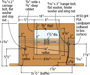
Cut the parts to the sizes given in the cutting list. Rout ¾”-wide × ¼”-deep grooves in the top surface of the top and the bottom surface of the carriage, as shown in the illustrations on page 81. Note that the grooves in the top run front-to-back, while those in the carriage run side-to-side. The grooves fit around the cross slides.
Cut the shape of the top and cross-slide mount. The top has a “fixed stop” on one side and a cutout in the other.
Then cut a 2¼”-diameter dust-collection hole in one of the end pieces. Next, you should drill a 5⁄16”-diameter pivot hole for the router mount in the back side.
Assemble the bottom, sides, ends and baffle (which is a dust-collector diverter) with glue and screws. Insert the carriage bolt that serves as the pivot for the router mount through the pivot hole in the back side, then screw the top in place. But don’t glue the top to the assembly – I found that out the hard way. If the pivot bolt happens to fall out, you can lose your religion trying to get it back in. (Of course, had I been smart, I would have epoxied the bolt in place.)
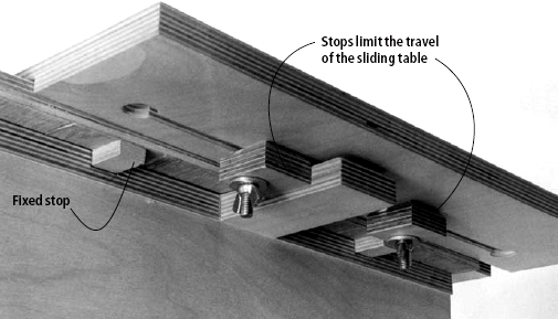
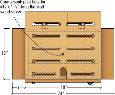
The sliding carriage has several straight slots with a ¾”-diameter hole at one end for you to mount the stops without having to remove the hardware. Just insert the head of the mounting bolt in the hole and slide the stop in.
Mounting the Router
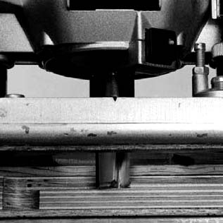
Attach the router to a clear plastic plate before putting it in the router mount. Because this router mounting plate is thinner than the board it attaches to, this arrangement gives you a fraction of an inch more depth of cut. More importantly, it lets you see what the router is doing as you cut.
To attach the plastic plate to the router mount, make a cutout and rabbet the edge to accept the mounting plate. Attach the router mounting plate to the router mount with #10 flathead sheet-metal screws. When installed, the router mounting plate must be flush with the work surface of the router mount. The heads of the screws must be countersunk in the mounting plate so they rest slightly below the surface.
Cutting the Slots
There are two types of slots in this fixture. The carriage has several keyhole slots – straight slots with a ¾”-diameter hole at one end. The holes let you mount the stops and clamps instantly, without having to remove the hardware. Just insert the heads of the mounting bolts in the holes and slide the stop sideways in the slot.

PROFILE
BACK VIEW

EXPLODED VIEW
The Joint Maker

Hardware
  ” × 2” carriage bolts (6) ” × 2” carriage bolts (6) |
| ” × 5” carriage bolts (3) |
| ” flat washers (15) |
| ” wing nuts (8) |
| ” fender washer |
| ” stop nut |
| ” × 3” hanger bolt |
| #10 × ¾” flathead sheet metal screws (8)& nuts |
| #12 × 1½” flathead wood screw |
| compression springs (3) 0.030 wire × 11/32” I.D. × 5” long |
| #8 × 1¾” flathead wood screws (45) |
| ” × 4” full-thread hex bolts (3) |
| ” T-nuts (3) |
You can make a counterbored slot in two steps. First rout the wide “counterbore groove” that forms the step inside the slots.

Then rout a slot down the middle of the groove, cutting completely through the stock in four ⅛”-deep passes.
The slots let you position the stops and clamps wherever you need them when making cuts. Note that these slots are counterbored, which helps hold the heads of the bolts so they don’t rub on the top of the fixture.
To make the keyhole slots, drill the ¾”-diameter holes first. Then rout ¾”-wide × ¼”-deep counterbore grooves using a straightedge as a guide. Without changing the position on the router guide, change bits and rout a 5⁄16”-wide slot through the middle of each groove.
The other slot used in this Joint Maker is the curved slot in the router mount. To rout this slot, attach the router to a router compass jig. Insert a pivot bolt through the compass and the mount, then swing the router in an arc as you cut.
Make the Cross-slide Mount
The cross-slide mount is a simple assembly, but you have to get all four of the slides positioned correctly for it to work well. The best way I found to do this was to use the tool itself as a glue-up jig.
Place a single layer of thin plastic in the grooves in both the top and the carriage (a plastic grocery bag works well). Then press the slides into their grooves on top of the plastic. Apply a thin bead of glue to the exposed surface of each slide. Place the cross-slide mount on top of the slides in the top, then place the carriage (with the slides in place) on top of it. Don’t worry if there’s glue squeeze-out; the plastic will prevent it from accidentally bonding surfaces that shouldn’t.
Make sure everything lines up properly and the back edge of the carriage is flush with the back of the Joint Maker. Then clamp the parts together and let the glue dry. After it sets, take the carriage, cross slide and Joint Maker apart, and trash the plastic.
Make the Stops and Clamps
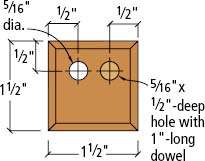
The stops and clamps are all attached to the carriage by carriage bolts. The stops are just blocks of wood with dowels protruding from the underside to keep them from rotating while in use. Chamfers around the bottom edges prevent sawdust from interfering with the accuracy of your setup.
I found that as sawdust builds up around the stops, it prevents the parts from making full contact. This, in turn, keeps you from positioning the parts correctly. The chamfers give the sawdust somewhere to go. You will still have to brush the dust away from time to time, but you don’t have to get every little particle.
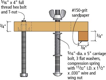
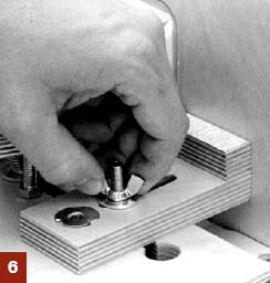
On the clamps, a compression spring around the mounting bolt automatically raises the clamp when you loosen the knob. A hex bolt threaded into a T-nut at the back of the clamp prevents the assembly from tipping when you apply pressure.
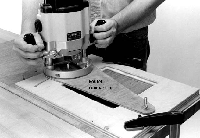
To rout the curved slot in the router mount, first make a router compass jig to guide your router in an arc. Drill the ”-diameter mounting hole in the router mount and mark the ends of the curved slot. Use the mounting hole as the pivot and swing the router in an arc to cut the slot.
Make as many clamps and stops as you think you’ll need. I made just three clamps and four stops, which I’ve found to be adequate for the work I do. But if you think you’ll need more, now is the time to make them.
As another option (if you’ve got a few extra dollars) there are a couple of hold-down clamps available from catalogs that will also work very well when attached to the Joint Maker (see “Some Store-bought Options to Improve the Joint Maker” on page 128 for more.
Final Assembly, Finishing
Give all the wooden surfaces a light sanding, then apply a durable finish to all parts of the Joint Maker: the router mount, carriage, cross slide, clamps and stops.
Apply a thin coat to all exposed surfaces, then rub down those surfaces that will slide together (such as the back and the router mount, or the top and the cross slide) with steel wool or fine abrasive pads. Then apply a coat of paste furniture wax to the sliding surfaces of the top, cross slide and carriage, and buff it out. The thin layer of wax lubricates the surfaces and helps the parts slide much more easily.
Attach the router mount to the Joint Maker with a pivot bolt, washer and a stop nut. Using the curved slot as a guide, drill a ¼”-diameter pilot hole for the hanger bolt in the edge of the top. Install the hanger bolt, fender washer, flat washer and wing nut, as shown in the illustrations.
Also install the hardware in the stops and clamps. The carriage and cross slide are not attached; they simply rest atop and slide on the Joint Maker.
Once you’ve done that, you’re ready to test it out on all your joint-making operations.PW
CARRIAGE LAYOUT - PLAN

CARRIAGE LAYOUT - BOTTOMVIEW

CROSS-SLIDE LAYOUT - PROFILE

TOP LAYOUT - PLAN

CLAMP DETAIL - PLAN
CLAMP DETAIL - PROFILE
STOP DETAIL - PLAN

STOP DETAIL - ELEVATION
Some Store-bought options to Improve the joint maker
When we had a chance to work with the Joint Maker in the Popular Woodworking shop, we were definitely impressed with the cleverness of the design. Our minds were spinning with the amazing number of operations that could be performed easily with this homemade jig.
We also let our minds wander a little further about some of the features of the jig. After adjusting the numerous wing nuts (especially when applying hold-down torque to such a small surface area), we decided that some very affordable handles would make the jig more user-friendly. T-handle, star and three-wing knobs are available for 50 cents to $2 each, and make gripping and tightening the adjusters a whole heck of a lot easier.
Another addition we felt would be useful were some optional manufactured hold-downs. While Nick’s hold-downs function well, there are a number of other hold-downs available for less than $5 that offer slightly better performance. The store-bought hold-downs shown at right will work with the slots as shown in the plans, and by purchasing them you’ll reduce the time necessary to build the jig and get you using it more quickly.
The jig knobs are available from a number of sources, including your local Lowes. The hold downs shown here are available from Hartville Tool (800-345-2396 or hartvilletool.com, item #60736) costs $10.95 and includes a solid aluminum hold-down, a bolt and a ¼”-20 knob.
–David Thiel


While the four-prong “star” knobs are easiest to grab, the two-prong “T” knobs require less clearance. The hold-down at left also works in the Joint Maker’s slots.
Using the Joint Maker to Create a Haunched Mortise-and-Tenon Joint
You can cut grooves on the inside of edges of rails and stiles with a straight bit. Lock the carriage to the base with a wood screw and feed the parts past the bit, guiding them along the mount.

To cut the mortise, clamp a stile to the carriage so the inside edge faces the router. Adjust the hex bolts so the clamp jaws sit squarely on the work while you tighten the knobs.
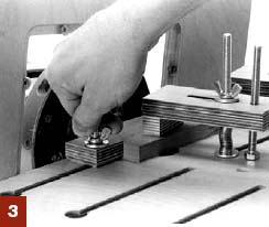
Secure a stop against the end of the stile to quickly align the other stiles. This makes it a lot easier to make the same cut in multiple pieces without having to set it up each time.
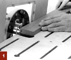
Advance the router bit to cut the full depth of the mortise. Holding the carriage, feed the stock into the bit no more than ⅛” deep at a time, moving it side to side.

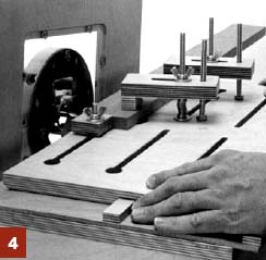
For the tenon, mount a rail on the carriage so the edge is perpendicular to the mounting plate. Secure stops against the rail to help you position the others for duplicate cuts.
You can use the wooden clamp as a stop to prevent the bit from cutting into the carriage as you work.

Once you set up the stops and clamps to cut the tenons just as you want them, feed the rail across the bit, cutting the underside of the stock. With the cutter below the work, you need to pull the work toward you to cut against the rotation of the bit.

To cut the tenon’s shoulders, turn the rail so the outside edge rests on the carriage and clamp it in place. Readjust the router bit and cut the haunch in the tenon, using the carriage to feed the work and control the cut.