Circuits
In order for electric current to flow, there must be a circuit for it to follow. A circuit is a complete loop or path that electricity can follow. There are three essential components of an electrical circuit: a voltage source, a load, and conductors to connect the load to the voltage source. When these three components are connected so that current can flow, we have a closed (completed) circuit.

A load is basically a source of resistance that converts electrical energy into some other energy form. For instance, a light bulb is a load. It has resistance and converts electrical energy into light energy and heat. Other examples of loads are electric motors, heating elements, and solenoids.
If a load’s resistance were to decrease, the current flowing in the circuit would increase. However, if the circuit were broken, as in a wire (conductor) being disconnected, no current would flow. This would be called an open circuit.
When current is flowing, each electron is carrying the voltage the length of the conductor: pushing the electrons ahead of them to keep moving forward, while being pushed themselves by those behind. When the line stops, it stops everywhere, thus when there is no clear path to their destination, as in the gap that occurs in an open circuit, electron flow stops entirely and the current is zero.
Ohm’s Law
The relationship between voltage, current, and resistance through a wire is summed up in Ohm’s law. Ohm’s law states that voltage (potential difference) in volts is equal to the current in amperes multiplied by the resistance in ohms. This is represented by the formula:
V = IR
V represents voltage, also known as potential difference, while I represents current, and R represents resistance. If the I symbol seems odd, think of current (defined as the amount of charge flowing past a point per unit time) as the intensity of charge flow. The other two are easier to remember.
The voltage source is the beginning and end of the circuit. The negative side repels electrons, forcing them to move through the circuit. The positive side helps by attracting electrons, and an electron emitted from the negative side will eventually traverse the complete circuit before arriving at the positive side. Remember that voltage is essentially electric pressure on a charged object, so the voltage source is ultimately responsible for electric flow in a circuit by pushing the electrons forward.
To put it another way, a non-zero voltage will produce a certain amount of current in a closed circuit for a given resistance, as shown by Ohm’s law above. Batteries, which have positive and negative terminals, are voltage sources (for example, a 12 V battery). A household electrical socket also provides voltage, which ultimately comes from the power plant. They are also referred to as power sources, because the electric current they create carries energy.
The conductor is just the wire that connects the load(s) and voltage source. For the sake of simplicity, the wire is often considered to have zero resistance. Although this is not true, the resistance in a conducting wire is often small enough compared to any given load that it can be ignored for most calculations. At zero resistance, Ohm’s law requires the voltage across such a conducting wire to also be zero, meaning the electrical pressure does not change from one side to another.
Remember, a load is any component with resistance that converts electrical energy into some other energy form. In accordance with Ohm’s law, were a load’s resistance to decrease, the current flowing in the circuit would increase. However, if the circuit were broken, as in a wire (conductor) being disconnected, no current would flow. This would be called an open circuit. This, too, can be explained by Ohm’s law, as the break or gap in the circuit is like a load with infinite resistance (recall from the previous section that air is a terrible conductor).
Series Circuits
An electrical circuit that has only one path for current to flow is known as a series circuit. A break (opening) at any point in the circuit will cause current to stop flowing in all parts of the circuit. The simplest possible circuit, one voltage source connected to one load by conductors, is an example of a series circuit.
Series Circuit

Since there is only one path for current to follow in a series circuit, the current flow will be the same in all parts of the circuit. It wouldn’t make sense, for example, if one million electrons were leaving the negative terminal of a battery each second, but two million were arriving at the positive terminal at the other end. It would be like a plane taking off from New York and then landing in Miami with twice as many passengers. Thus, the current passing through any single load in a series circuit is the same.
I1 = I2 = I3 = . . .
On the other hand, what happens if multiple loads were found in a series circuit? If two or more loads are added to a series circuit, their resistances add together, creating what’s called the total or effective resistance across the circuit.
Rtot = R1 + R2 + R3 . . .
Voltage, which refers specifically to a difference in electric potential (“electric pressure”) at two different points (like from the negative to the positive terminals of a voltage source), can also be calculated across a single load. This is also known as the voltage drop across a load, and the total of all voltage drops across each load in a series circuit is equal to the total voltage of the complete circuit, which is equal to the voltage of the voltage source itself.
Vtot = V1 + V2 + V3 . . .
Try applying these ideas to solve the following problem.
-
Three different loads with different rated resistances are wired in series. Which of the following will be the same through all of them? - the voltage drop
- the resistance
- the current passing through
- the heat given off
Explanation
Choice (C) is correct. The current passing through one point in a series circuit has to be the same in other parts of the circuit, as there is nowhere else for the current to go.
Parallel Circuits
It is much more common for loads to be wired in parallel. With this arrangement, each load is wired in a separate path. If any one of these paths were to have a break or gap, current flow would still continue through the other paths, so there would still remain a closed circuit.
Parallel Circuit

Parallel circuits are the exact opposite of series circuits in that voltage is the same throughout each parallel branch of the circuit, while current flow varies. Since voltage is a measure of the difference in electric potential between two points, the voltage across alternate paths connecting the same two points in a circuit must also be equal.
V1 = V2 = V3 = . . .
On the other hand, current flow becomes divided when there are parallel paths. It’s commonly misstated that electricity follows the path of least resistance. This is not actually true. Electricity actually follows every possible path, though a larger proportion of electrons will take a path of low resistance while a smaller proportion will take a path with higher resistance. For a parallel circuit, therefore, the total current through the circuit is equal to the sum of currents through each closed path.
Itot = I1 + I2 + I3 . . .
What about the effective resistance of a circuit when multiple loads are wired in parallel? It’s natural to instinctively think that adding more loads is bound to add more resistance, but this is not the case. This is a little less intuitive at first glance, so consider an analogy.
There’s a big sale on at a popular retail store. One of the aisles is choked with customers trying to grab the best deal. The jostling customers, abandoned shopping carts, and crates of items waiting to be shelved all create resistance, making it difficult to move forward and slowing the rate at which people move through the aisle. In this analogy, the people are electrons, and the rate at which they move is the current value.
Suddenly, a store clerk clears away a pile of merchandise that was blocking an adjacent aisle. This aisle, too, has a lot of junk in the way. It may even have higher resistance than the original aisle, as it has more stuff. Even so, some shoppers opt for that cramped but less crowded aisle. The total number of shoppers passing through the store each moment is now greater, with the addition of that parallel path.
Likewise, adding a load in parallel, even if that load’s resistance is high, decreases the total or effective resistance of a circuit, because even though it has resistance, it provides an additional path while doing nothing to constrain the existing one. The formula for adding resistances in parallel is a slightly more complicated one, but it’s very useful.

Study the example below.
| Question | Analysis |
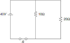
| What is the approximate amount of current passing through switch S when it is closed? | Step 1: The question asks for current through the whole circuit. Effective resistance of the circuit and total voltage are needed to calculate this. |
|
Step 2: There are two loads in parallel, so the parallel resistances formula is needed. Given the effective resistance (Reff), Ohm’s law can be used to determine the current drawn. The reciprocals of the resistance values are R1 = and R2 =  . Find the least common denominator and add:
|
| Step 3: The predicted value is 6 A. | |
| (A) 0 A (B) 2 A (C) 4 A (D) 6 A |
Step 4: Select answer choice (D). |
Now try one on your own.
-
Which of the following would not increase the rate of direct current flow, I, through a conductor? - decreasing effective resistance via a variable resistor
- increasing voltage
- adding a resistor to the circuit in parallel
- adding a resistor to the circuit in series
Explanation
Answer choice (D) is correct. Using process of elimination, (A) would decrease the overall resistance of the circuit, which, according to Ohm’s law, would increase current given a constant voltage source. Choice (B) would also increase current flow if resistance remained constant. Choice (C) would also decrease the overall resistance of the circuit and increase current. However, adding a resistor in series would increase effective resistance, which means a decrease in current drawn.
Series-Parallel Circuits
The most popular arrangement is the series-parallel circuit. A series-parallel circuit has some components, such as an on/off switch, wired in series with a number of loads that are connected in parallel.
Series-Parallel Circuit

Most residential wiring circuits are series-parallel. Wall outlets are wired in parallel, but are all fed from a circuit breaker (shown in the diagram as a fuse) that is wired in series. Switching off the circuit breaker will turn off power to all of the outlets. However, if the circuit breaker is on, voltage is provided to all of the outlets whether there are loads plugged into them or not.
Determining the total effective resistance across a series-parallel circuit is a step-by-step process. Use the appropriate formula for each group of resistors, either in series or parallel, to simplify the circuit to fewer and fewer calculated effective resistances until a single value for resistance has been found.
To determine the voltage drop or amount of current flowing through any particular load, combine Ohm’s law with the rules for current and voltage in series and parallel wiring to solve for a given variable of any particular load.
| Question | Analysis |
| In the diagram shown, all three resistors have a resistance of 4 Ω. What is the effective resistance of the circuit? | Step 1: The question asks for the effective resistance of a series-parallel circuit. |

|
Step 2: The two parallel loads can be combined into a single effective resistance. The effective resistance of the last two loads can be added to the first load’s resistance since they’re in series with the first load. 
|
| Step 3: The prediction is 6 Ω. | |
(A)
 Ω
Ω(B) 4 Ω (C) 6 Ω (D) 12 Ω |
Step 4: Select choice (C). |
Now try the question below on your own.
-
What is the amount of current passing through the 3 Ω resistor in the circuit pictured? 
- 3 A
- 4 A
- 6 A
- 12 A
Explanation
The answer is (B). Since a switch is open on the branch of one of the parallel 6 Ω resistors, it can be ignored. That means this circuit will behave like a simple series circuit. The two connected resistors sum to an equivalent resistance of 3 + 6 = 9 Ω. Using Ohm’s law, the current flowing through the 3 Ω resistor (and one of the two 6 Ω resistors) can be calculated as I =
 =
=
 = 4 A.
Electrical Power
Electrical power is a term that refers to the actual rate at which energy is provided to and consumed by an electric circuit. Power is expressed in watts (joules per second) and can be calculated by multiplying the voltage (in volts) applied to the circuit by the current (in amperes) that flows in the circuit. This is represented by the formula:
P = IV
Each electron flowing through a circuit or wire has energy. How much energy depends on the voltage applied. Electrons moving through a large voltage have more energy. On the other hand, a higher current means more electrons passing by each moment. So an equivalent rate of energy delivery can be achieved by a smaller number of electrons each moment (lower current) with a larger amount of energy per electron (higher voltage), or a larger number of electrons each moment (higher current) with a smaller amount of energy per electron (lower voltage).
This formula applies not only to the rate of energy delivery (power found in long-distance power lines) but to the rate of energy production (power provided by a generating plant) and to the rate of energy consumption (power usage of an appliance or load). The word consumption is actually a little bit misleading, as energy is never used up but just changes form. A forty-watt (40 W) light bulb doesn’t really use up 40 joules every second. It transforms 40 joules of electrical energy to 40 joules of light and heat energy each second.
| Question | Analysis |
| An electric generator provides a power supply to a cabin at the North American household standard of 120 V. If the effective resistance of the cabin’s wiring is 30 Ω, what is the power usage of the generator? | Step 1: The question asks for the power of the generator. |
| Step 2: Both current and voltage provided by the generator are needed, but only voltage and resistance are given. However, these can be used to find current using Ohm’s law. Now, power can be calculated. 
|
|
| Step 3: The predicted answer is 480 w. | |
| (A) 4 W (B) 150 W (C) 480 W (D) 3600 W |
Step 4: Select choice (C). |
Now try a question on your own.
-
The power usage of a coffee pot is 1200 W while running, and is powered by a standard North American 120 V electrical supply. What is the resistance of the coffee pot? - 10 Ω
- 12 Ω
- 120 Ω
- 1200 Ω
Explanation
Answer choice (B) is correct. Using the power law and solving for current, I =
 = 10 A. Then using the current and voltage values in Ohm’s law and solving for resistance, R =
 = 12 Ω.
Standard Electrical Units and the Metric System
When using Ohm’s law and other electrical formulas, it is important to keep in mind that the quantities used must be expressed in ohms, amperes, volts, and watts. If any of these quantities are given in other units, these should be converted before making calculations with them.
Any of these base units can be modified with metric prefixes. For example, smaller generating plants typically measure their power output in megawatts (MW), while cardiac doctors may measure tiny electrical signals in the human heart on the scale of milliamps (mA).
For more detail on metric system prefix values, please refer to the measurement information at the beginning of the Physical Science section of chapter 9: General Science.