Combustion Systems
Fuel System
The fuel system is responsible for maintaining the correct air-fuel mixture for efficient engine operation. If the air-fuel mixture is not adjusted correctly, drivability, emission control, fuel economy, and engine service life can suffer.
Up until about 35 years ago, it was most common for the air-fuel mixture to be determined through mechanical means. This was accomplished through the use of a carburetor, which was very reliable but incapable of providing the precision required in modern fuel systems. Due mostly to the demands of emission control regulations, the carburetor has been made obsolete in favor of electronic fuel injection. This system is controlled by an onboard computer and incorporates a feedback function that gives it flexibility to adjust to changing engine conditions very quickly.
Components
The following are the major components of an electronic fuel-injection system:
- Electric fuel pump: located in the vehicle’s fuel tank, the fuel pump supplies fuel under pressure to the fuel injectors.
- Fuel filter: filters contaminants from the fuel before it reaches the fuel rail.
- Fuel rail: a manifold that supplies fuel under pressure to the inlets of all the engine’s fuel injectors.
- Fuel pressure regulator: regulates pressure in the fuel rail according to intake manifold vacuum. Excess fuel is bled to the fuel return line, where it is sent back to the fuel tank.
- Fuel injector: sprays fuel into the intake air stream as it receives electrical signals from the powertrain control module (PCM). The location of the injector will determine the specific type of fuel injection system being used on the engine.
- Powertrain control module (PCM): another name for the vehicle’s central computer, it is responsible for control of all functions associated with the engine and transmission.
- Intake manifold: distributes air to the intake ports on the cylinder heads.
- Intake air filter: all air entering the engine passes through the air filter, which removes airborne contaminants that could damage internal engine parts.
- Throttle body/throttle plate: the throttle plate, which is connected to the throttle pedal, controls engine speed and output torque.
Fuel injection system designs
When fuel injection systems first came into common use, they were designed to utilize either one or two injectors mounted in a throttle body that took the place of the carburetor. This is known as a throttle body injection system or TBI. While this system proved to be reliable, it was not capable of providing a high enough level of fuel control to meet emission control requirements. Most engines are now built with either multiport fuel injection, which has an injector for each engine cylinder, or direct injection, where the fuel is directly injected into the combustion chamber.
With multiport fuel injection, the injectors are located in the intake manifold, with their spray directed toward the intake valves. As air enters the intake manifold, it will flow all the way to the cylinder head before fuel is injected into it. This allows for much better air-fuel mixing and prevents fuel droplets from falling out on the intake manifold runners. With direct injection, a high-pressure fuel injector is located to spray highly pressurized fuel directly into the combustion chamber. Therefore, only air flows over the intake valves and enters the combustion chamber. Fuel can then be sprayed directly into the combustion chamber at an optimized point in the compression stroke. Also, the fuel acts as a coolant to the hot compressed air in the combustion chamber, which allows the engine to be designed with even greater levels of compression, which further improves power and efficiency.

Maintenance
The fuel-injection system requires very little maintenance. The filters (both air and fuel filters) must be changed periodically, based on the manufacturer’s recommendations. Manufacturers may also require periodic cleaning of the injection system. Aside from that, fuel injection systems are built to give reliable service with a minimum of maintenance.
Ignition System
One of the most critical vehicle systems is the ignition system. Without it, combustion cannot take place, so the engine will not run. The ignition system must generate high-voltage sparks at the correct time in order to make the engine run smoothly and efficiently.
Components
The ignition system can be divided into two distinct subsystems: the primary ignition system and the secondary ignition system. The primary is the low-voltage part of the system, whereas the secondary is high voltage.
The following are the major components found in the primary ignition system of a basic electronic ignition system:
- Battery: supplies power to the ignition system for starting the engine.
- Ignition switch: turns the engine on and off by switching power to the ignition system.
- Primary coil winding: the low-voltage winding in the ignition coil. This is made up of several hundred turns of relatively heavy wire.
- Ignition module: a transistorized switch that turns the primary current on and off.
- Reluctor and pickup coil: responsible for generating a signal that operates the ignition module. The reluctor is mounted on the distributor shaft, and generates a signal in the stationary pickup coil as it rotates with the distributor.
- Distributor: driven by the engine’s camshaft, the distributor is responsible for timing the spark and distributing it to the correct cylinder. Like the camshaft, the distributor turns at one-half the speed of the engine.
The following are the major components found in the secondary ignition system of a basic electronic ignition system.
- Secondary coil winding: the high-voltage winding in the ignition coil. This is made up of several thousand turns of fine wire, wound around the primary coil winding.
- Coil wire: transmits high voltage from the secondary coil winding to the distributor cap.
- Distributor cap and rotor: directs high voltage from the coil wire to each cylinder in the firing order. This is a switching mechanism that allows one ignition coil to serve all the engine cylinders.
- Spark plug wires: transmit high voltage from the distributor cap to each spark plug.
- Spark plugs: threaded into the cylinder head, the spark plug protrudes into the combustion chamber and generates the spark to initiate combustion.

Primary ignition operation
When the driver turns the ignition switch to the “run” position, current is sent from the battery, through the ignition switch, and on to the primary coil winding. From the coil winding, that same current flows through the ignition module and back to the battery through the vehicle ground circuit. The low-voltage (primary) section of the ignition system is responsible for the control of the secondary, or high-voltage section. Whatever happens in the secondary system is in response to the events in the primary section.
The ignition system works because of a phenomenon known as electromagnetic induction. If a magnetic field moves across a stationary wire, voltage is induced in the wire. Another dimension of this principle is that electric current passing through a wire will produce a magnetic field around that wire. This means that electric current can be used to generate a magnetic field, and a magnetic field can be used to generate electric current.
Secondary ignition operation
The collapse of the magnetic field in the primary coil winding induces a high voltage in the secondary winding. These secondary system voltages typically range from 20,000 to 40,000 volts, and modern systems can go even higher. This huge increase in voltage in the ignition coil is achieved because of the large number of turns of wire in the secondary winding relative to the primary. The magnetic field in the primary winding cuts across a much larger number of turns of wire in the secondary, creating a step-up effect in the coil.
The high-voltage current in the secondary winding must be directed to the correct cylinder in the firing order. This current is directed through the coil wire to the center tower of the distributor cap. From this point, it flows to the rotor, which is mounted on top of the distributor shaft and rotates with the distributor. As the engine turns, the rotor will direct the current to the appropriate cylinder and send it through the spark plug wire to the spark plug. The electric arc at the spark plug is used to initiate combustion.
Current ignition system design
Since engine performance relies heavily on accurate ignition timing, engineers look carefully at how to eliminate more moving parts from the ignition system. This led to the elimination of the distributor in a design named the distributorless ignition system or DIS. DIS systems use one ignition coil to operate two spark plugs, so a V-8 engine would require four separate coils instead of one. The increase in the number of coils allows each coil more time to build up its electric charge and, therefore, deliver a more powerful spark when the time comes to discharge. However, this system still utilized spark plug wires, which degrade over time and eventually need replacement for the DIS system to function properly.
The most recent ignition system designs have eliminated the spark plug wires all together. These systems are known as coil-on-plug ignitions. Individual ignition coils are mounted directly onto the spark plugs, and the discharge of the coils is controlled by the vehicle computer system. While the incorporation of computer control has increased ignition system complexity, the elimination of moving and high-maintenance components has led to very accurate control of spark timing, which is critical for optimum engine efficiency and emissions, as well as increased reliability of the ignition system.
Exhaust Systems
The exhaust system is responsible for removing waste gases from the engine. It must do this in a way that allows these gases to flow freely, muffles the sound of the exhaust, and keeps the gases and heat away from the vehicle cabin and its occupants.
Components
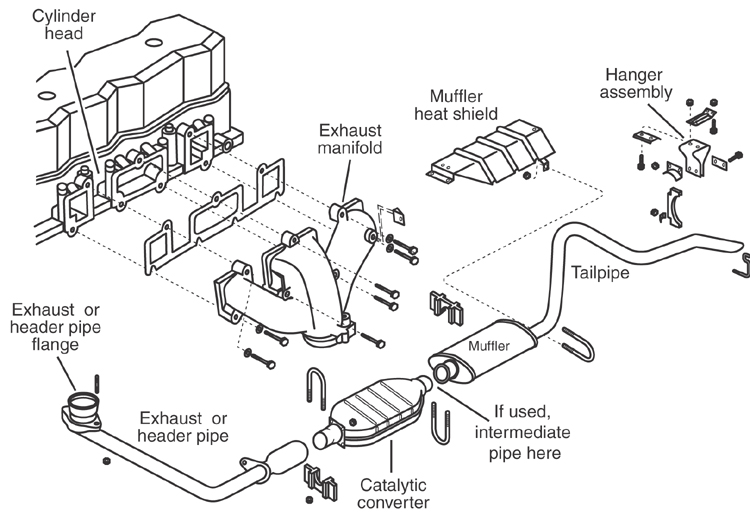
Typical components found in an exhaust system include the following:
- Exhaust manifolds: attached directly to the exhaust ports on the cylinder head. The majority of the exhaust heat and noise is focused on the exhaust manifolds. These are often made from cast iron for durability under high heat conditions.
- Catalytic converter: responsible for converting the toxic components of engine exhaust into relatively harmless compounds such as carbon dioxide and water.
- Muffler: incorporates an expansion chamber and sound absorbing material to diminish loud exhaust noises.
- Tailpipe: the exit point for exhaust gases as they enter the open atmosphere. The tailpipe normally exits at the rear of the vehicle.
Operation
As gases flow from the exhaust ports of the engine, the exhaust manifold collects them. On a V-type engine there would be two exhaust manifolds, one for each cylinder head. These manifolds feed the gases into steel exhaust pipes, which connect the major components of the exhaust system.
The exhaust gases are then sent into the catalytic converter. High heat is developed in the catalytic converter as it reduces the toxic components of the exhaust to gases that are less toxic. Some vehicles use two, and even three, catalytic converters in an effort to meet emission control regulations.
After leaving the catalytic converter, exhaust gases are directed into the muffler. The muffler has expansion chambers built into it that absorb the loud sounds generated by the engine’s combustion. The muffler is normally located toward the rear of the car, somewhere after the catalytic converter and before the tailpipe.
Even after passing through the catalytic converter, engine exhaust is highly toxic. The most dangerous of the toxic gases emitted by the engine’s exhaust is carbon monoxide, an odorless and colorless deadly gas. It is extremely important that these gases be routed in such a way that they do not come into contact with the driver or passengers in the vehicle. This usually involves sending these gases to the rear of the vehicle where they are dissipated to the open air by the tailpipe.
To increase engine efficiency and power, the exhaust system can be tuned to match the design of the engine. “Tuned” exhaust manifolds are often known as header pipes. The idea is to allow exhaust gases to flow more freely and allow the engine to breathe better. Increased performance is usually gained at the expense of durability, as header pipes are much more fragile than cast-iron exhaust manifolds.
Maintenance
Inspect the system from time to time for physical damage; there should be no restrictions and no leaks. The system should also be tight in terms of its mounting brackets and clamps. Any damage should be repaired immediately.
The catalytic converter will enjoy a long service life if the vehicle’s engine is kept in good running order. An engine that burns oil or has ignition or fuel system problems will damage the catalytic converter.
Questions on the ASVAB may ask you to recall the components or functions of the various systems of a vehicle. Questions may be situational, asking you to interpret the situation at hand and to make an assessment based on your foundational knowledge of automotive systems. Let’s take a look at a sample question from the area of combustion systems, which covers the fuel system, the ignition system, and the exhaust system.
| Question | Analysis |
| Multiport fuel injection prevents |
Step 1: This question asks you to recall one of the benefits of multiport fuel injection. Step 2: There is nothing to simplify, but remember what you know about multiport fuel injection. Step 3: One of the features of multipoint fuel injection is the ability to precisely atomize the fuel into the intake air stream within the intake manifold runners. This fine atomization enables the fuel to be suspended in the intake air stream as fine particles and prevents larger fuel droplets from falling out onto the walls of the intake manifold runners. |
|
Step 4: The correct answer is (B). Answer choice (A) is incorrect because injected fuel does not flow over the exhaust valve. Choices (C) and (D) are incorrect because, generally, multiport fuel injection does not directly affect engine overheating or engine fires. |
Now give this one a try on your own.
-
A major component of the primary ignition system is the - reluctor and damper coil
- inductor
- primary resistor
- reluctor and pickup coil
Explanation
The correct answer is (D). The reluctor and pickup coil are responsible for generating a trigger signal that operates the ignition module. Answer choices (A), (B), and (C) are not major components of the primary ignition subsystem, and therefore are not correct.