Part 6: Electronics Information (EI)
9 Minutes 20 Questions-
Directions: In this section, you will be tested on your knowledge of electronics basics. For each question, select the best answer and mark the corresponding oval on your answer sheet.
-
A load - has very low resistance and conducts current throughout the circuit
- is a device that converts electrical energy into heat, light, or motion
- is a voltage source
- switches electrical current off and on
-
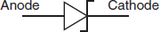
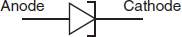
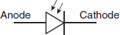
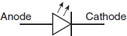
Which of the following symbols represents a photosensitive diode? -
One hertz is equivalent to - one cycle per second of any continuous process
- an acceleration of 1 m/s2
- a change in frequency of one cycle per second per second
- the negative of the period
-
A(n) is an element that freely conducts electricity. - insulator
- conductor
- semiconductor
- molecule
-
Which of the following CANNOT describe an “earth ground” in home electricity? - a buried conduit
- a copper rod driven into the ground
- a device made to protect occupants from electrical shock
- a device for measuring electrical resistance
-
Electron flow theory states that - electrons flow best through liquids
- electrons flow from areas of excess negative charge to areas of less negative charge
- electrons flow from areas of excess positive charge to areas of less positive charge
- electrons can only flow from one area to another if there is no resistance
-
The “electrical pressure” that causes electrons to flow in one direction through a conducting path is a result of - a voltage
- a difference in resistance
- parallel paths
- a wire moving downhill
-
This is the symbol for which type of meter? 
- voltmeter
- ammeter
- ohmmeter
- galvanometer
-
What type of circuit does this symbol represent? 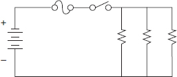
- parallel circuit
- series-parallel circuit
- series circuit
- short circuit
-
Under a constant voltage, increasing resistance results in current flow - dropping
- rising
- staying the same
- changing direction
-
Increasing the voltage in a circuit and keeping resistance the same will result in - increased current flow
- decreased current flow
- current flow staying the same
- zero current flow
-
Several loads in series have different resistances. Given that the same current flows through each of them, what relationship does Ohm’s law predict between resistance and voltage drop? - Larger voltage drops occur across loads with greater resistances.
- Smaller voltage drops occur across loads with greater resistances.
- Larger voltage drops occur across loads with lesser resistances.
- An equal voltage drop occurs across each load in series, independent of resistance.
-
Capacitive reactance decreases as electrical frequency - decreases
- increases
- varies
- gets closer to DC
-
Which is the emitter in the transistor symbol below? 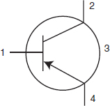
- 1
- 2
- 3
- 4
-
Which of the following CANNOT be used to make the magnetic field in a coil of wire stronger? - increasing the number of turns of wire in the coil
- increasing the current flowing through the coil
- inserting an iron core into the middle of the coil
- inserting a dielectric between each coil
-
Whenever current passes through a resistance, is most often generated. - voltage
- capacitance
- heat
- light
-
The formula for Ohm’s Law is - V = I × R
- V = I − R
- V = I + R
- V = I ÷ R
-
If current is able to pass through a diode, the diode must be - reverse-biased
- forward-biased
- open
- grounded
-
Transistors are turned on and off by voltages applied to their - collector
- emitter
- base
- cathode
-
If each resistor in this circuit equals 1,000 ohms, what is the total resistance in this circuit? 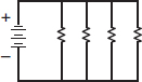
- 250 ohms
- 500 ohms
- 1,000 ohms
- 4,000 ohms