I. DRAWING LEWIS STRUCTURES
A. LEWIS STRUCTURES ARE DIAGRAMS USED TO REPRESENT COVALENTLY BONDED SPECIES THAT SHOW VALENCE ELECTRONS AS DOTS. THE FOLLOWING IS A METHOD FOR CONSTRUCTING THEM:
1. Calculate the total number of valence shell electrons, taking into account any charges present by adding for negative charges, and subtracting for positive charges.
2. In a species with more than two atoms, decide which atom is the central one (this is usually obvious, but if in doubt it will be the least electronegative atom but never hydrogen).
3. Use one pair of electrons (represented by two “dots”) to form a covalent bond between each of the terminal (outer) atoms and the central atom.
4. Arrange the remaining electrons to complete the octets of the terminal atoms. (Hydrogen only needs two electrons to complete its valence shell.)
5. Place any remaining electrons on the central atom, if necessary expanding the central atom’s octet.
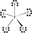
i. Atoms in period 3 of the periodic table and below, can use empty d orbitals in their valence shell to expand those valence shells beyond just the s and p sub-shells. This is called an expanded octet. See the following diagram.
6. If the central atom lacks an octet, form multiple bonds (double or triple) by converting nonbonding electrons from terminal atoms into bonding pairs between the terminal atoms and central atom.
i. One bonding pair of electrons represents a single covalent bond that in turn can be represented by a single line (–); two bonding pairs represent a double bond represented by a double line (=); and three bonding pairs represent a triple bond represented by a triple line (≡).
7. Some atoms need less than 8 electrons (typically Be and B) and remain electron deficient without full octets. An example is BCl3. See the following diagram.

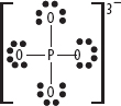
8. If the covalently bonded species has a charge (usually a polyatomic ion), then use square brackets to enclose the Lewis structure and add the charge as a superscript, as shown in the following diagram.
9. Examples of Lewis structures are shown in the following diagrams.
i. CO2
![]()
ii. N2
![]()
iii. NH3

iv. NH2OH
![]()
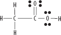
v. CH3COOH
vi. CH3OH

A. RESONANCE IS USED WHEN MORE THAN ONE FEASIBLE LEWIS STRUCTURE EXISTS
1. Resonance often occurs when a double bond can be positioned in more than one place.
2. Bond lengths and strengths found in the species are “averages” of the single and double bonds present.
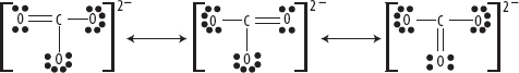
3. An example is the carbonate ion, as shown in the following diagram. Bond lengths and strengths are found to be intermediate between single and double bonds and have orders of 1⅓ (i.e., four bonds divided amongst three oxygen atoms).
Resonance Structures of the Carbonate Ion CO32–
III. TYPES OF COVALENT BOND
A. ANY SHARED PAIR OF ELECTRONS IS CONSIDERED TO BE A COVALENT BOND, BUT DIFFERENT TYPES EXIST
1. A sigma (σ) bond is formed between the overlap of two s orbitals or an s and p orbital along the bond axis between two atoms.
2. A pi (π) bond is formed between the overlap of two p orbitals perpendicular the bond axis between two atoms. Pi bonds are weaker than sigma bonds.
3. Single covalent bonds are composed of only sigma bonds, double covalent bonds are composed of one sigma and one pi bond and triple covalent bonds are composed of one sigma and two pi bonds.
IV. SHAPES OF COVALENTLY BONDED SPECIES
A. LEWIS STRUCTURES AND VSEPR ALLOW THE PREDICTION OF THREE-DIMENSIONAL (3D) SHAPES
1. The electron pairs around the central atoms in a covalently bonded species repel one another in order to get as far apart as possible. This is called valence shell electron pair repulsion, or VSEPR.
2. Determine the 3D shapes of covalently bonded species, as follows:
i. Draw the Lewis dot structure for the species.
ii. Count the electron pairs (both bonding and nonbonding) around the central atom.
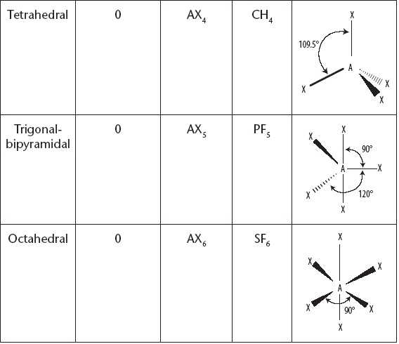
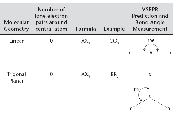
iii. Use the following charts to recall the correct shape, name, and bond angles.
Molecular Geometry with Central Atom Having No Lone Electron Pair
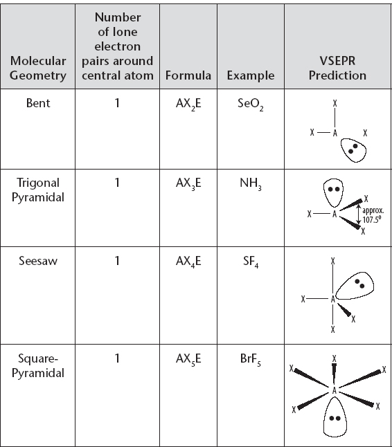
Molecular Geometry with Central Atom Having One Lone Electron Pair
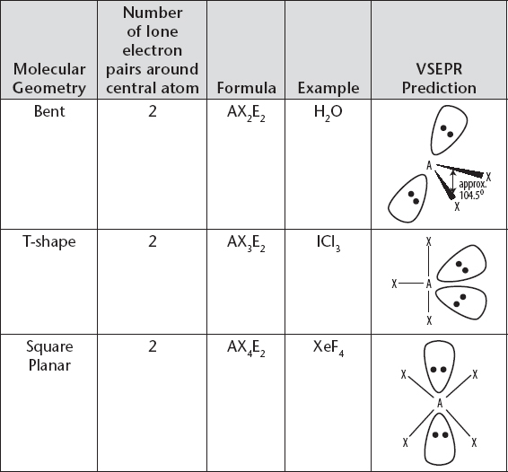
Molecular Geometry with Central Atom Having Two Lone Electron Pairs
Molecular Geometry with Central Atom Having Three Lone Electron Pairs
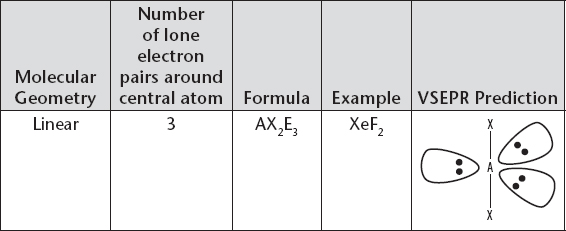
You must learn and commit to memory the molecular shapes, their names, and bond angles. HOWEVER, if you can use intuition by remembering the principle behind VSEPR, then your life will be easier. For example, ask yourself how do two or three electron pairs around a central atom get as far apart as possible? If it is obvious to you that two electron pairs would spread out to opposite sides of the central atom, and that three electron pairs would arrange themselves in a triangle around the central atom, then you may be able to “work out” the linear and trigonal planar shapes for those species, and the corresponding bond angles of 180° and 120°, without the need for pure memorization.
3. See the following additional notes about Lewis structures, shape, and bond angles:
i. A nonbonding or lone pair (LP) will repel more strongly than a bonding pair (BP). When comparing bond angles, you can see that this has the effect of altering the bond angles in molecules that have a similar total number of electron pairs, but where the total is comprised of different combinations of bonding and lone pairs.
a) For example, CH4 (4BP, 0LP), NH3 (3BP, 1LP), and H2O (2BP, 2LP) all have a total of four pairs around the central atom, but have bond angles of approximately 109.5°, 107.5° and 104.5°, respectively.
ii. For the purposes of predicting shape, multiple bonds can be considered as single bonds.
a) For example, carbon dioxide can be considered to be surrounded by two electron pairs (negative centers) and is therefore linear.
4. Hybridization:
i. Atomic orbitals are mixed to form hybrid orbitals that aid symmetry.
ii. Hybridization can be determined by considering the total number of electron pairs around the central atom, and then using the appropriate number of s, p, and d orbitals.
iii. When considering hybridization, count double and triple bonds as single bonds because pi bonds are caused by overlap of unhybridized p orbitals.
iv. A total of two pairs = sp hybrid; three = sp2 hybrid; four = sp3 hybrid; five = sp3d hybrid; and six = sp3d2 hybrid.
V. POLAR BONDS AND POLAR MOLECULES
A. WHEN SEPARATE ENDS OF A BOND OR MOLECULE CARRY A PARTIAL POSITIVE OR NEGATIVE CHARGE, IT IS SAID TO BE POLAR
1. Dipoles are created within covalent bonds by a difference in electronegativity.
i. More electronegative atoms attract the shared pair of electrons toward themselves, and as a result that end of the bond becomes slightly negative.
ii. The movement of electrons away from the more electropositive elements leaves them relatively positive.
iii. Bonds where the atoms at either end have the same or very small differences in electronegativity (around a difference of 0.4 or less), are considered nonpolar.
2. In order for a molecule to be polar overall, polar bonds must be present, PLUS the dipoles should NOT cancel out due to symmetry.
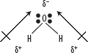
3. The dipole moment can be indicated by an arrow that points toward the negative charge center with the tail of the arrow indicating the positive charge center, or by using δ+ and δ− to indicate small areas of positive and negative charge, as shown in the following diagram.
![]()
4. For example, consider water. Opposite ends of the molecules carry different charges and there is no canceling of the dipoles, so the molecule is polar as shown in the following diagram.
5. Now consider hexane and carbon tetrachloride, neither of which are polar molecules but this is due to different reasons.
i. In hexane (C6H14), carbon and hydrogen have very similar electronegativities and as a result the bonds are effectively nonpolar.
ii. In carbon tetrachloride (CCl4), on the other hand, has four polar C–Cl bonds but because of its symmetrical shape is nonpolar overall. The partial positive charge is located at the center of the molecule and the partial negative charges equally spread around it, causing the dipoles to cancel.

A molecule that has a single lone pair will always be polar, since there will be nothing similar to cancel out the large area of negative charge that the lone pair introduces.