Chapter 2
Easy Electronics
If you’re new to making electronic projects, you’ll need to build up some basic technical skills like wiring, soldering, and identifying electronic components. (If you are starting from scratch, check out Charles Platt’s excellent guide, Make: Electronics.) No worries: even a beginner can build the following easy electronic toy and game projects. You’ll learn how to use the same electronic sound circuit to make two different projects: a retro 1980s music toy and conductive ink game cards. But first up: projects that show how to quickly hack an existing toy to add a new “fun-ction.”
Noninvasive Hacked ’Bot
When making new toy prototypes, I often harvest old broken toys to reuse the parts such as motors, gear trains, or radio control transmitters and receivers. No need to reinvent the wheel—literally!
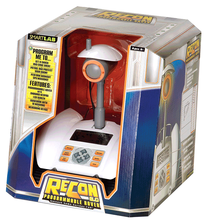
SmartLab Toys’ ReCon is a programmable tank-treaded robot that’s full of goodies. To play, write a program of step-by-step instructions for the robot to do; for example, “Go forward 48 inches . . . turn left 90 degrees . . . STOP! . . . play a sound . . . go backward 24 inches . . .” Then press Go and the program instructs the robot how to execute the mission. Open ReCon up and you’ll find lots of cool stuff inside, including a nifty dual-motor drive module with built-in optical wheel counters.

Rather than take it apart, here’s a noninvasive hack that takes advantage of ReCon’s features, while adding a fun new function, to make a Root Beer Pong ’Bot. You’ll need just a few small pieces of thin metal (I used brass), a light bulb, a momentary contact single-pole, single-throw micro switch, and some wire.

I wanted to add a sensor to control ReCon in real time. Fortunately the toy’s nonvolatile memory retains your program, even when the batteries are removed. I used this feature to add a kill switch, something that temporarily interrupts the battery power to the toy.

I made a thin, double-sided contact that slips in between the batteries and one of ReCon’s battery contacts. Each side has a piece of brass soldered to wire with a nonconductive piece of plastic double-sided tape in between. One brass tab touches the battery to route the power to the SPST switch. Normally, the power is sent through the switch right back to the toy through the second brass tab.
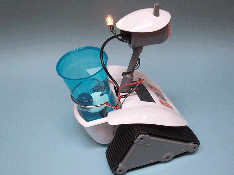
But if the switch is activated, the power is disconnected from the toy and instead goes only to the light bulb. ReCon stops in his tracks and the bulb lights up—that’s a “kill.”
Next, I created a simple program that turns ReCon into a moving target game. As it follows a programmed path across the floor, it also plays a series of sound messages announcing an ever-decreasing point jackpot. Try to toss the ball into the cup, throw the switch, and stop ReCon before it counts down to zero. Whatever point value you last heard is your score!

If you want to try programming this game into your own ReCon, look in the appendix for a listing of my program.
A close-up of the battery compartment shows the two wires with a thin insulator between them at the lower right. The red wire steals the power from the batteries, sends it to the outboard switch, which sends it either right back via the green wire or to the external bulb.
Throw the ball in the ReCon’s cup before it gets away!

The weight of the ball triggers the switch, stopping ReCon and illuminating the “kill” light.
Super-Cheap Electronic Die Challenge
Suppose you needed to build an electronic die for a board game. Sure, you could use discrete components to build a clock circuit that sends a continuous signal into a decade counter and binary-coded decimal to seven-segment decoder, for example. Or you could write some random number generator code for an Arduino and use discrete LEDs. That’s obvious and has been done before. But professional toy inventors have to be crazy clever and get the same effect but for an insanely low, dirt-cheap cost. Can you do it?
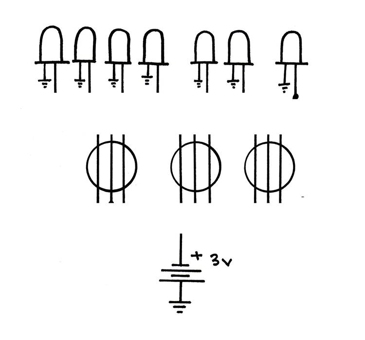
Here’s one approach that costs next to nothing: LEDs wired up with some cleverly designed single-pole, double-throw switches. Each switch is made of three parallel wires and a metal ball in a cage. When you shake the cage, the ball randomly lands on either one pair of wires or the other pair. Only one pair of wires completes the circuit, lighting the LED.


Here’s how I made an electronic die: Wire up four LEDs to one switch, two LEDs to the next switch, and a single LED to the last switch. Shake them all together and you’ll get a random number of LEDs to light up, from zero to seven. For games that need a number from one to six, just “roll again” if you get zero or seven lit LEDs.
Here’s your challenge: can you rewire the switches so that you’ll get only numbers one through six? That is to say, no zeros and no sevens. Here’s a blank diagram. Go ahead and draw your wiring here, but use a pencil: you may need to erase as you go. When you’re done, go to the appendix to see my solution!
This challenge is more of a thought experiment, but if you want to try actually building the die, the following are step-by step instructions.

MAKE:

1. Make a ball cage from acrylic by drilling three large through-holes (three times the diameter of your conductive ball) and then three small holes at 90 degrees to each large hole.

2. Make a small square panel to just fit inside the box, and drill holes for the seven LEDs.
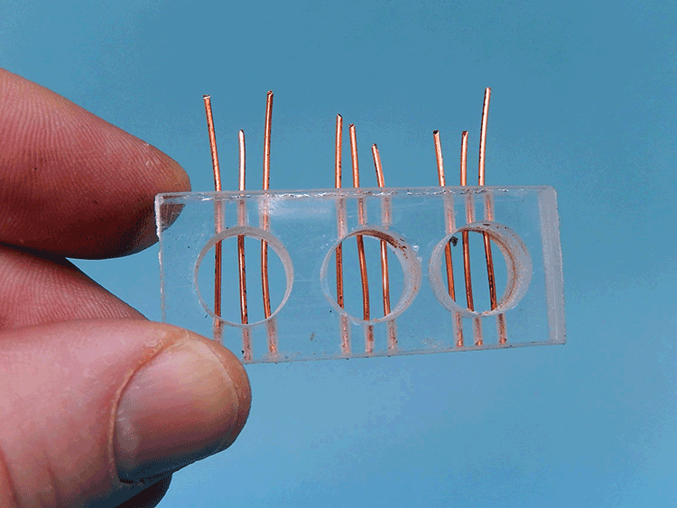
3. Strip the heavy gauge solid core wire, cut into pieces, and thread into the small holes. Superglue the ends to tack it all in place.

4. Solvent-bond the ball switches to another small vertical piece of acrylic so that the wires are held horizontally. Cover with a clear piece of plastic on top to trap the balls inside. Wire up the switches and LEDs.
TEST:
5. Wire up the battery and optional on/off switch and test the circuit by making a truth table of all inputs and noted outputs. LEDs one through six should light up; no zero and no seven.

6. Assemble and carefully solvent-bond the panels inside the cube (cut a hole in the back for the on/off switch).

ROLL:
7. Your electromechanical die is complete.

8. For a more finished look, paint the cube white. Leave the top clear and then add a piece of frosted mylar on top for a backlit look.
Talking Booby Trap
Having trouble with people snatching your top-secret stuff? Need help getting some privacy? Here’s a sneaky MacGyver-y gizmo you can make to keep those snoops away! It’s a talking booby trap: record your personalized message or sound effect and then hide it in a strategic place. If it’s disturbed, the intruder will hear your message telling him or her to get lost!

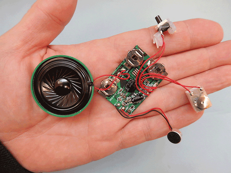
This design uses a sound recording/playback unit available from RadioShack (part 276-1323). It’s a prewired module, complete with audio board, speaker, and controls, that will record up to 20 seconds of sound in nonvolatile memory. As of this writing, you can still get this module in remaining RadioShack stores or online, but if you can’t get it, you can use any record-and-play toy.
You can also hack the guts of a sound recording/playback greeting card.
- Disassemble the clothespin—the wire spring is too stiff. Reassemble the pin as shown so the spring is used only as a fulcrum pivot. Wrap a rubber band around the jaws of the clip a couple of times. Slide the rubber band closer or farther away from the fulcrum to adjust the tension. The clip should open easily, but still close together all the way.
Add an extension to the top leg of the clothespin. Bend a small strip of stiff brass so that it lies flat when the clothespin is held open. Drill 2 small holes in the brass and attach it to the clothespin with screws.
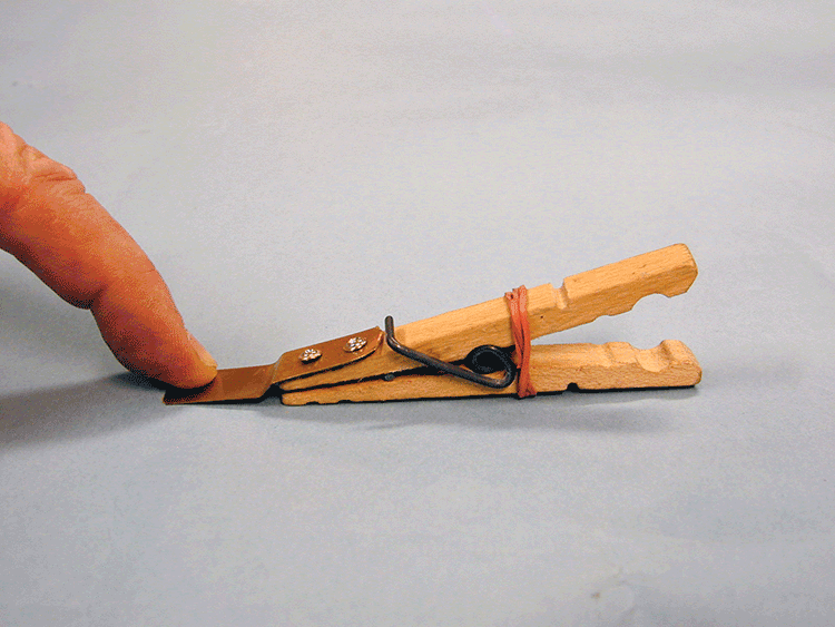
- Wrap the jaws of the clothespin with the aluminum tape. Poke a small hole in the aluminum and attach a short wire to each jaw. Twist the wire and crimp the tape over firmly to make a good electrical connection.

- Install the 9V battery and test the circuit: press and hold the Record button (the red LED goes on) and speak loudly into the speaker. When you’re done, release the record button, then press the gray button on the PC board to hear your recording.
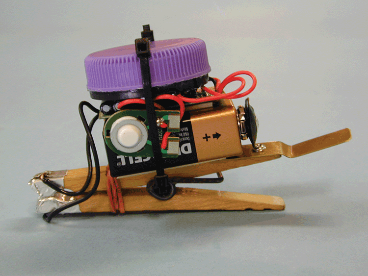
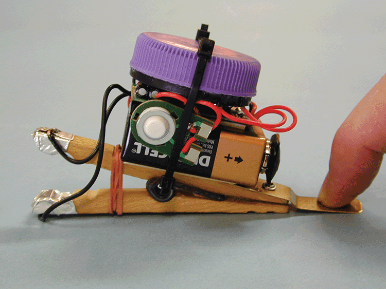
- You can improve the sound of the naked speaker significantly by adding a resonant chamber. I used a plastic bottle cap from a gallon milk jug; it’s just the right diameter. Superglue it to the front of the speaker.

- Now modify the circuit to wire up the clothespin. Look for the gray rubber-domed Play switch on the PC board. Bend the three metal tabs on the back and remove the button.

- Feed a wire from the clothespin jaw through the tab hole and over the edge of one of the traces. Carefully solder the wire to the trace—don’t short out the traces! Do the same thing for the other jaw wire and solder it to the remaining trace.

- Now the clothespin will act as a Play switch: when the jaws touch, the sound plays. Try it! To prevent the sound from playing, place a slip of paper as an insulator between the jaws.
- To finish, stick the battery to the clothespin with double-sided foam tape, and then stick on the PC board. The speaker is foam-taped on top. Use cable ties to cinch everything together and tuck in the microphone and Record switch wires to neaten it all up.
- Use your Talking Booby Trap lots of ways:
- Place a diary, journal, or any object on the brass tab. The weight of the object keeps the clothespin open and armed. Camouflage the trap by placing something in front. If anyone lifts the book—WHOOP!—the alarm goes off!

- Use the Talking Booby Trap to shame your lunch-lifting coworkers. Hide it behind your food items inside the fridge at work. If anybody touches your lunch, out blasts “KEEP YOUR HANDS OFF MY LUNCH!” Now everybody will know who the secret food-stealer is!
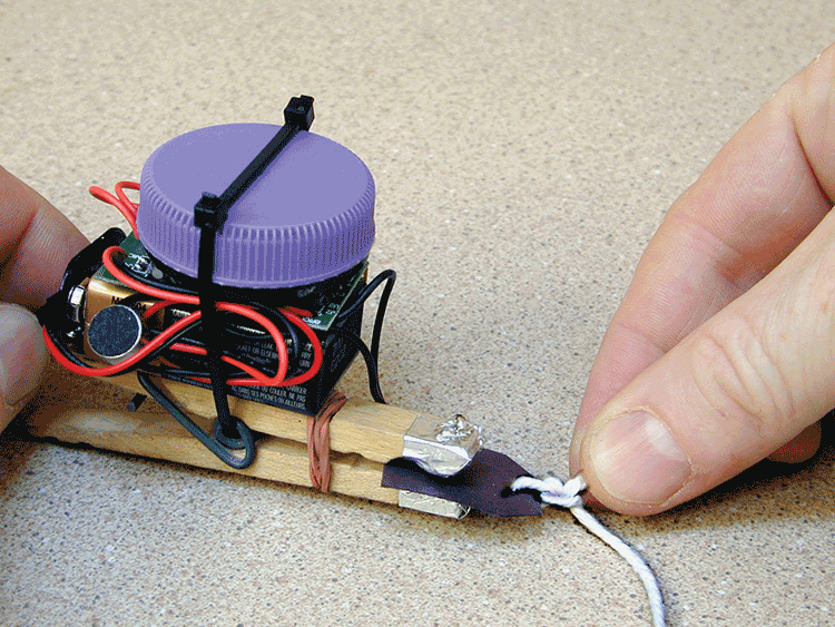
- Tie a string to a small piece of paper and slip it in between the clothespin jaws. Then tie the other end to any object. You’ll know if anyone tries to take your treasure: pulling the string trips the trap. Use monofilament fishing line instead of string for an invisible alarm.
- Open the Talking Booby Trap and slip it under a closed door. If anybody opens the door, you’ll know it. Record a scolding “Bad dog!” message in your own voice to keep pets in their place while you’re away! You can also arm a drawer or sliding door.

- You can also leave an audio reminder for someone special by arming their cell phone or car keys. They’ll really get the message!
- Place a diary, journal, or any object on the brass tab. The weight of the object keeps the clothespin open and armed. Camouflage the trap by placing something in front. If anyone lifts the book—WHOOP!—the alarm goes off!
Personalized Talking Doll
The recording module from the Talking Booby Trap can be used in lots of other ways, like making this talking plush doll. Just record your own personalized sound or message on the circuit and stuff it into a doll. You can use an existing doll, or do what I did: create a custom doll from scratch.
For his Knetz Comics website, my brother Jack Knetzger created a talking corn kernel character named Niblet. I thought I’d surprise him by bringing his character to life in a talking doll.

I made the Niblet character using a simple two-piece “pillow doll” design. I made a pattern of the curved corn kernel shape and cut out two identical pieces of stretchy yellow cloth. Next, I pinned the cloth pieces together face-to-face and sewed them together around the edge, leaving a small opening. Then I turned the shape inside out and used fabric pens to draw the eyes and mouth. I stuffed the doll with polyester stuffing and placed the circuit inside.
Instead of using a bottle cap for the resonant chamber, I used a plastic cup the same diameter as the speaker so you could still hear the sound inside the doll’s stuffing.

One fun detail: I made a cloth tag for the doll from the cartoon’s logo by ink-jet printing the design on iron-on transfer paper and then ironing it onto a strip of cloth. I folded the cloth over and stitched the Play button inside the tag. (After recording the sound I snipped one of the leads to the Record button so that I wouldn’t inadvertently press it again and erase it!)

Then I sewed the tag into the seam of the Niblet doll and closed it up with some hand stitches.

When you squeeze the tag, the Niblet doll says his famous tag line “. . . but Lou, I’m just a kernel of corn!”


Scan this QR code to see a demo video of Niblet the Talking Doll in action!
You can create your own custom talking pillow doll by following my steps. Blow up a photo of a friend’s face, ink-jet print it onto some T-shirt transfer material, and iron it onto a piece of cloth. Cut it out and sew it into a pillow, and stuff with stuffing and the module. Record a funny saying or sound effect and you can literally put words in your friend’s mouth! Or make talking animal dolls or figures from your favorite comics, movies, or TV shows.
Breadboard ’Bots
Many an electronic project starts on a protoboard, and for good reason. You can quickly wire up a circuit just by connecting resistors, integrated circuits (ICs), and other components using the push-in connector rails—no soldering needed! You can also easily disconnect and reconnect the wiring to revise your circuit as you go. For a little more fun, I added some Sugru® and some small plastic tubing to create these cute little Breadboard ’Bots.
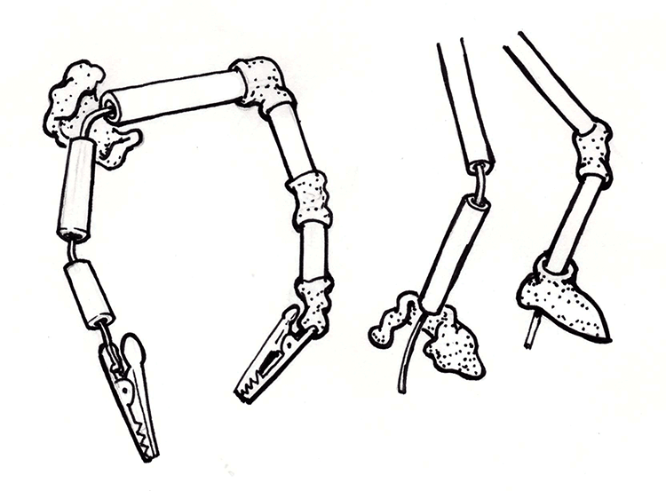
This makes poseable electronic robot components. The Sugru acts as a flexible joint and holds the parts together. Thread some stripped 22-gauge copper bell wire through short pieces of 1⁄8″ plastic tubes and solder electronic parts to the wires. Add blobs of Sugru to make elbow, knee, and shoulder joints. Leave the wire sticking out the bottom of the feet for use with protoboards. The alligator clip hands are wired together to grab and connect the ’Bot to another wire, component, or ’Bot.
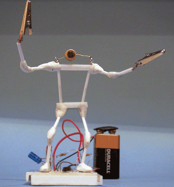
You can make Breadboard ’Bots out of almost any component, like resistors, capacitors, and batteries, and it’s especially fun when the component is an input or output device like a LED or mini speaker.

I thought it would be fun to make a ’Bot version of the photocell in Forrest M. Mims, III’s classic 555 timer oscillator circuit. This ’Bot’s photocell head is connected to a protoboard oscillator circuit through both his feet. Pose this Photo ’Bot facing up at you. When you shine a light on his face, the 555 timer circuit plays a squealing audio tone; the brighter the light the higher the pitch. Sweeeeeeeeeeet!
There’s no limit to the size or look of your Breadboard ’Bots. Who says you can’t have fun with functional circuits?
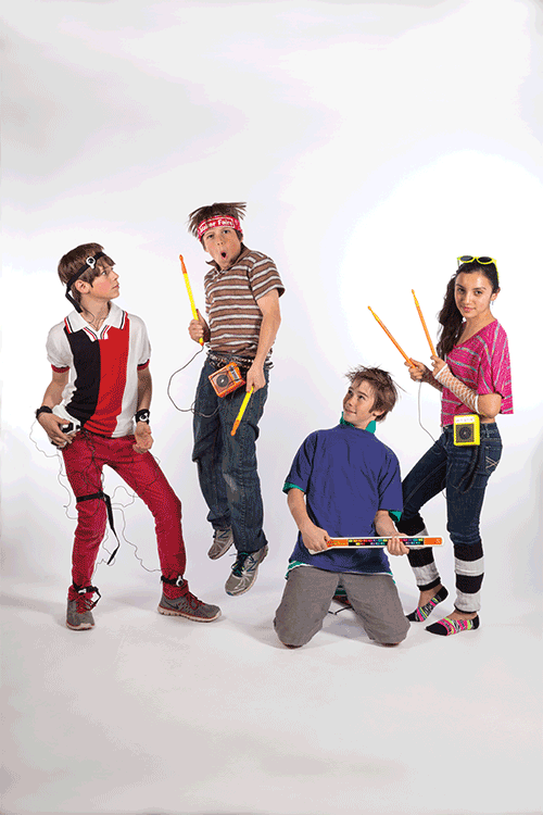
1980s Musical Toys
The 1980s brought big changes for electronic toys. Advances in integrated circuits meant electronics became inexpensive enough to be used in toys of all kinds, and especially in musical toys. Instead of plastic ukuleles or plinky pianos, these musical toys were something new, with new sounds, new methods of playing them, and new toyetic forms.
Playskool’s cheap and cheerful entry into musical preschool toys was Major Morgan. He had a keypad with overlays that showed how to play a tune using color-coded grids. Just swap out his overlay for a new song. The rigid plastic keypad offered no tactile feedback (oww!) and the sound circuit produced just a single BEEP note at a time, but no matter: kids had fun with this musical soldier.


Mattel was aiming for an older crowd with their Bee Gees Rhythm Machine. This cute keyboard featured two disco-licious features: a pitch-bending wheel (wow-weEEEee!) and a toy version of a beat box with three different drum-and-bass loops. You could choose disco, Latin, or pop beats and adjust the tempo. The synthesized rhythms featured a busy bass line with a synth drum, and you could play along on the mini piano keys. This instantly kitschy music toy was used by the group Kraftwerk on their hit song “Pocket Calculator” in 1981.
Mattel’s Star Maker Guitar promised “hot” sounds but with only one string, musical choices were limited. You’d pluck the fat string and press it against the molded plastic frets to change pitch. The best part was a built-in “fuzz tone” effect for a fat, distortion-soaked sound. Unlike its real-world counterpart with magnetic pickups, this toy guitar had an optical pickup that “saw” the motion of the vibrating string. The speaker was mounted directly underneath the string producing endless feedback and long sustain. Young would-be Eddie Van Halens, shred on!

How about a drum set—without any drums? Nasta’s Hit Stix were a big hit, that didn’t actually hit anything. Kids could play “air drums” with a big sound. Inside the tip of each drumstick was an inertial switch that triggered the snare drum sound circuit when the stick was hit or shaken. It also triggered a trend in other “air instruments.”


One of the weirder toys was Hasbro’s Body Rap. Strap on an array of little switches and then slap your own thighs, ankles, wrists, and head to beat out a rhythm of sampled drums, cymbals, and even the spoken words body and rap. The 80s hairdo was not included.


Perhaps the most iconic 1980s music toy was the Magical Musical Thing from Mattel. The TV commercial featured a kid playing melodies with one finger on the toy’s keypad strip—and finishing by playing it with his head! The version sold in Japan showed a kid playing it with his butt—“POOU!” The toy’s circuit was designed around the cheapest and most basic building block of digital electronics: the 4049 CMOS hex inverter chip.
Scan this QR code to see and hear these music toys in action!
Usually used for decoders and multiplexers, the lowly 4049 was reimagined by Mattel’s thrifty engineers to create musical tones. Three of the IC’s six logic gates were linked head-to-tail with a resistor and capacitor to create a simple, self-oscillating on-off, on-off square wave generator. The output of this oscillator was hooked up to the remaining three invertors in parallel. Their combined outputs were just enough to directly drive a speaker—no audio amplifier needed!
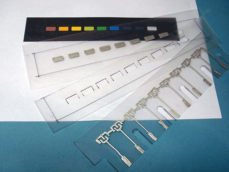
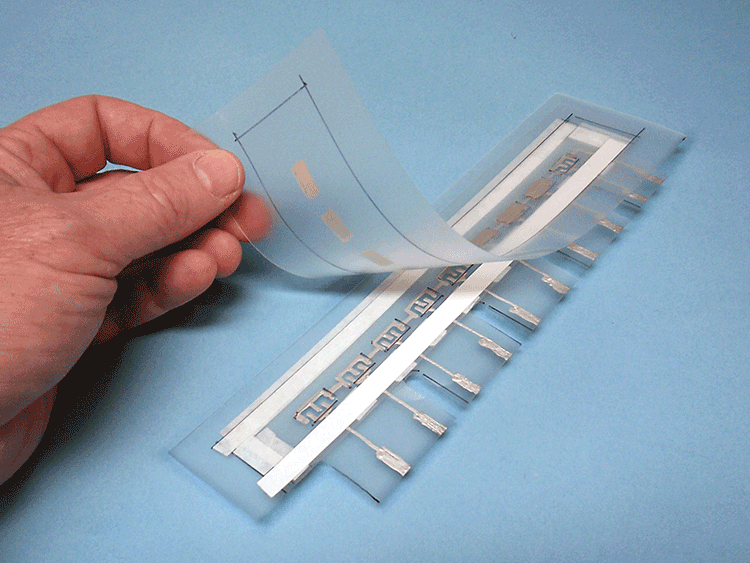
A network of resistors created the various musical tones. This was done using a cleverly designed membrane switch pad. The top and bottom layers were made from a single folded piece of mylar, printed with conductive silver traces connecting strips of resistive paint. The middle layer was a die-cut insulated spacer with holes positioned to make touch points, each labeled for a different color-coded musical note. Touching the membrane pressed together two conductive strips, which completed the circuit through a path of resistors, producing a single musical tone. The shorter the path, the less electrical resistance, the faster the circuit oscillates, the higher the pitch! Beep—Boop! Follow the color-coded notes to play a song or slide it over your body for a flourish of notes.
Musical Thing

Now you can make your own custom mini-version of this classic 80s toy. Wire up the circuit, draw a membrane keyboard, and make a housing (or put it in some repurposed container). This DIY redo has a new added feature: a circuit-bending touch point.
1. Wire the Circuit!

This reproduction circuit is quite simple with a minimum of components. You can easily solder it up with point-to-point wiring on a perf board. Layout isn’t critical, but I placed the 8 trimmer pots in one neat row. After the board is done, cut it down to minimize its size.
Instead of the fixed printed resistors, this version has a trimmer pot for each of the 8 notes so you can tune them individually. Strip the ends of the ribbon cable. Solder the end of each of 8 wires to one of the trimmers. Solder a ninth wire to the circuit board for connection A. Solder a mini clip to the other end of each of the 10 wires. The tenth wire connects directly to pin 2—that’s for the “circuit bending” pad. It doesn’t need a trimmer; your fingertip provides the resistance value.

Solder the rest of the components following the wiring diagram.
2. Test and Tune!
Test the circuit: add the battery, and touch the clip at point A to each of the other clips. You should hear a BEEP tone for each clip. Twist the trimmer pots to adjust the musical tones’ pitch. Compare pitches from a piano or keyboard, or use a guitar tuner app to tune the 8 notes to a diatonic (do-re-mi) scale, like the white keys on a piano: C, D, E, F, G, A, B, C.
3. Make the Keypad!

The membrane keypad has 3 layers, like a sandwich; you’ll draw conductive traces on the upper and lower layers. The middle “meat” layer is just a spacer with some holes cut into it.
Find the clip-and-use templates in the appendix and cut them out. Tape a piece of mylar over the first template. If you're using frosted mylar, be sure to lay it frosted side down. Trace the cut outline with a thin permanent marker. Use the conductive ink pen to trace the circuit layout. Be sure to shake the pen well between strokes—some pens have a ball inside that works as an agitator. You’ll have to very gently squeeze the barrel and press the valve tip down at the same time as you pull the pen across the mylar to make a uniform generous line. Join line segments while still wet for best conductivity.
Don’t puddle the paint on too thick—it’ll crack instead of flex when the mylar is curved. When the paint is dry, test each of the traces with a continuity tester and touch up with the conductive ink as needed.

Use the second template to make the other half of the keypad. Trace the cut-out pattern with a permanent marker and color in the switch pads with the conductive ink.
The third template needs no conductive ink: just trace the outline and cut out the holes for the middle spacer layer.
To assemble the keypad, place the first layer with the conductive ink–side up and carefully align holes of the middle spacer layer over the first layer’s switch pads. Add the topmost layer, with the conductive ink–side down, aligning the pads over the holes.
Tape the layers together temporarily and hook up the clips.


Press the switch pads to test your circuit. You should hear a beep each time you press and hold a switch pad. Again, touch up any traces or switch pads with a little extra conductive paint, if needed.

Trim the layers to size with a craft knife. Use the paper punch to make radiused inside corners as strain relief.

Use double-sided tape to fasten membrane switch layers together (don’t put tape over any traces).

I added a colorful label on top with numbered touch points.
4. Play!
Reconnect the clips and play away! Adjust the trimmer pots to sweeten your tuning. Tune the eight notes to a do-re-mi scale as before for a useful set of notes. Or you can tune them to anything you want—including the first eight notes of any song for easy auto-play. Just swipe your finger across the keypad to play! Lick your fingertip and touch the last keypad position for some fun circuit bending sounds, from a low growl to a high squeal, and everything in between.
You can play with the Musical Thing circuit as-is, or put it in a project box or housing.
Making a Custom Housing
Here’s how I made a custom molded housing for my Musical Thing. I wanted a miniature version of the original toy, so I vacuum-formed some plastic shells to enclose the circuit.


I made a symmetrical wooden pattern and used it to vacuum-form two identical parts. I used one for the top housing and flipped a second one over for the bottom.

I marked the desired thickness with a surface gauge and trimmed off the excess.
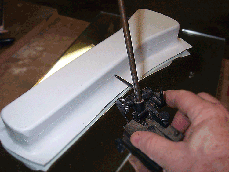
I milled some slots in the top housing to thread the keypad connections through.


I drilled some sound holes for the speaker and then mounted the speaker, circuit board, and battery inside. I reinforced the rim of the top housing with some strips of plastic to make a lip all around the edge for the bottom housing to grip. I use methyl ethyl ketone (MEK) to quickly fasten the styrene parts together. See the appendix for more tips.
I painted the bottom housing a bright magenta. I taped the keypad in place using double-sided tape and attached the clips before closing the top and bottom shells. Looks and plays great!

The Electronic Connection
You can use the same sound circuit as in the Musical Thing project to make a different toy that plays conductive ink games. That’s what Mattel did when they made The Electronic Connection in 1980.

Decades before Drawdio, Mattel’s The Electronic Connection used an ordinary pencil as part of an electronic circuit to create a range of audio tones. The carbon in the pencil marks made on a piece of paper (and in the pencil itself) acted as a feedback resistor.
(Fun fact: the term lead pencil really is a misnomer; the stuff inside pencils is actually graphite, a form of carbon.)
The longer and skinnier the pencil lines, the higher the electrical resistance and the lower the audio tone created by the oscillator. Short, fat lines had more conductive carbon, giving a lower resistance and making higher-pitched tones. Combined with clever circuits printed on cards with conductive inks, The Electronic Connection let kids play electronic versions of pencil-and-paper games, including making music, spelling games, math quizzes, mazes, and more. I invented it in 1979—and even got a patent for it!
Build It!
To make your own version of The Electronic Connection, build the same electronic circuit as the Music Thing project with the same parts but eliminate all the trimmer pots and membrane keypad switches. Instead, just solder a wire with an alligator clip to the connection marked A and another wire with an alligator clip to the connection from pin 2 on the 4049 hex inverter chip.


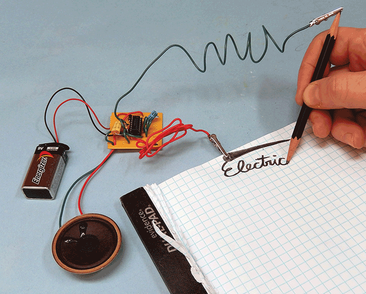
Try It Out!
Sharpen both ends of a 2B (not 2H!) or softer pencil and attach one of the alligator clips to the pencil. Draw a thick, fat patch of pencil-marking near the edge of a piece of paper. Connect the free alligator clip directly on that mark. When you touch the pencil tip to the pencil mark you complete the circuit and hear an audio tone: BEEEEEP! Make crazy sound effects from a low growl to a high squeal as you draw with the pencil and add more and more conductive carbon lines to the circuit: zzzzzeeeEEEEEE! Have fun making sounds and drawing paths and pictures. You can also use your fingers to touch and complete the circuit. Hold the pencil tip in one hand and touch the pencil marks on the paper. Just making the sounds with the circuit is fun by itself—but there’s more.
More Fun with Game Cards!
The next step is to create game cards using conductive ink pens to draw circuits. Find and cut out the clip-and-use cards in the appendix. For a longer-lasting card, laminate the paper onto thin cardboard (like a file folder) with some glue or double-sided tape, then cut out.
Color in the blue lines with conductive ink. Let the ink dry completely, then color in the red areas with pencil. Press down hard for a dark pencil line. Use a 2B or softer pencil and press firmly to fill in the resistance values, as shown in red, with a nice thick layer of pencil. Hook up the alligator clips and use the pencil as a stylus to play the games.

Try these fun electronic circuit game cards.
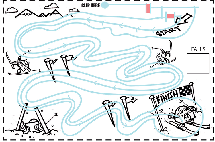
Dexterity Ski Run
Here’s how to play this easy skill game: start your pencil probe on the center line at the Start. You’ll hear a low tone—that’s good. Now trace the path of the center line toward the Finish. Don’t press or draw; just touch lightly with the pencil tip to keep the tone playing. Be careful! If you stray or lift the pencil, the tone stops: that’s a “fall.” Make a check mark in the Fall box, go back to Start, and go again. If you really stray, you’ll hear a high-pitched tone: that’s a double fall. Make two marks in the score box, go back to Start, and try again. What’s the fewest number of falls you can make to get to the Finish? Can you do a perfect run? Think it’s too easy? Hold the pencil in your other hand!
3-In-1 Sound Maze
This game is a maze that magically changes sound to direct you to one of three different goals. First, pencil in one of three goal circles. Use the pencil to completely fill in one of the three circles to make an electronic connection. Go to Start and lightly touch the pencil tip as you trace a path through the maze. Listen to the buzzing tone. As long as the tone you hear keeps getting higher, you’re going the right way. If the tone you hear starts to fall, that means you’re going the wrong way. Retrace your path and keep going, following the rising tones until you get to Finish. Then, erase the goal circle and color in a different one: the maze changes sounds as you trace to the new goal.

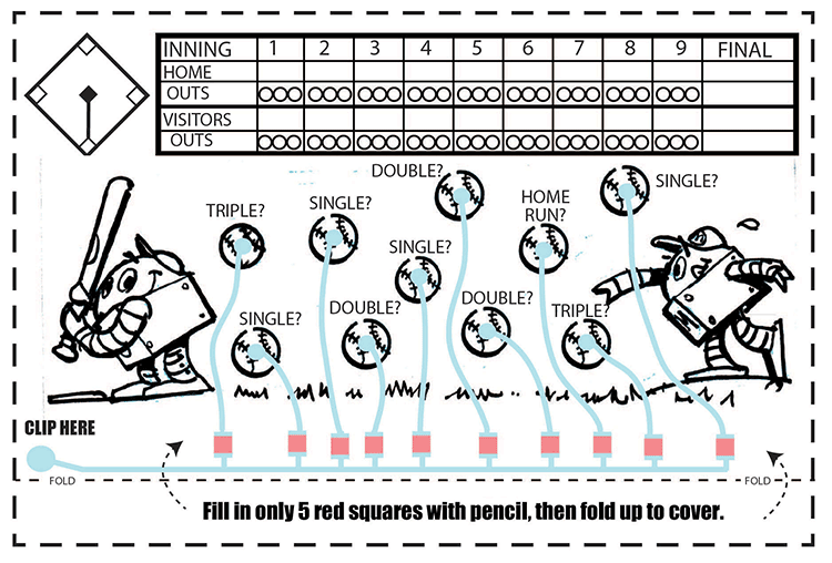
2-Player Baseball
Here’s a baseball game for two players with hits, outs, and innings.
At the start of the inning one player secretly chooses five of the “hit” baseballs and colors in their five red squares with pencil. Each filled-in ball will make a buzz sound when touched with the pencil. Then fold the paper over to hide the colored-in choices. The second player “bats” by choosing a ball and touching it with the probe. If there is no tone, it’s a hit! Mark the base runners on the diamond lightly with the pencil and bat again by choosing a different ball. But if you hear a buzzing sound, that’s an out! Update the scoreboard and keep playing. Keep tallying bases, runs, and outs just like in real baseball. After three outs, players switch sides: now the first player will bat after the second player erases and colors in five red squares. Will he fake out his opponent and keep some of the previously colored hits as outs again? That’s up to you . . . play ball! You can play nine whole innings of conductive ink fun.
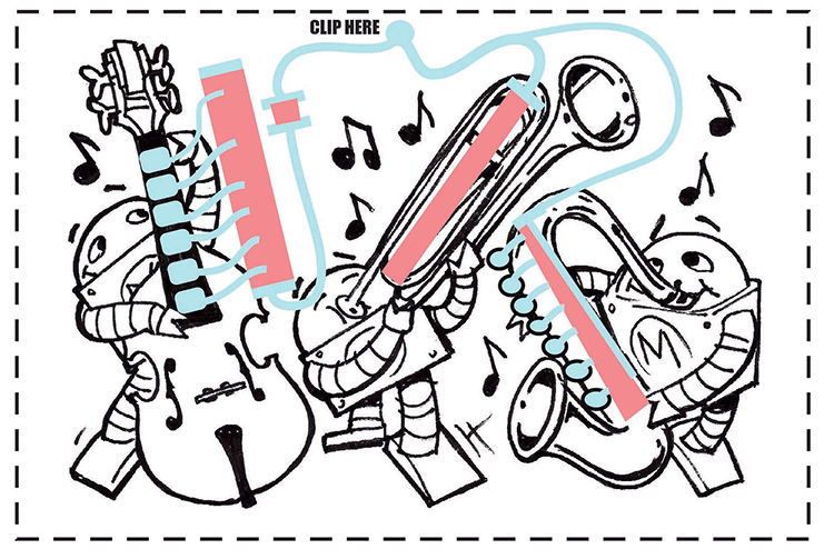
Makey Bot Music
Three Makey bots are playing some music: a low-pitched bass, a sliding trombone, and a high-wailin’ sax!
Trace the blue lines with conductive ink, then color over the red areas with pencil. Hook up the alligator clip to the card. Touch the pencil tip to the spots on the various instruments. The bass plays low notes. The sax plays high notes. Slide the tip along the trombone to make a sliding trombone sound! Slide your way across the trombone to play a melody.
Cross-Grid Strategy Game
This is a strategy game for two players. The first player to complete a continuous line that connects all the way across the grid and sounds the buzzer is the winner!
On each player’s turn, he or she draws a line connecting two of their shapes. (Press firmly to draw solid pencil marks along the dotted lines.) The “circle” player draws on the dotted lines connecting any two adjacent circles. The other player, playing “squares,” draws on the dotted lines connecting any two adjacent squares. No diagonal lines are allowed. Players cannot cross their opponent’s lines. Keep taking turns coloring in lines until one player has drawn a continuous line connecting all the way across the grid.
To claim a win, touch the pencil tip to your shape’s “Win Test” spot. If you hear a buzz or growl tone (no matter how low-pitched) you win!
Carefully erase all the lines to play again.
