1
Building Structures
BUILDING STRUCTURES
Buildings—the relatively permanent constructions we erect on a plot of land for habitable use—have developed over the course of history from simple shelters constructed of sticks, mud-brick, and stones to the more sophisticated constructions of concrete, steel, and glass of today. Throughout this evolution of building technology, what has remained constant is the enduring presence of some form of structural system capable of withstanding the forces of gravity, wind, and oftentimes, earthquakes.
We can define a structural system as a stable assembly of elements designed and constructed to function as a whole in supporting and transmitting applied loads safely to the ground without exceeding the allowable stresses in the members. While the forms and materials of structural systems have evolved with advances in technology and culture, not to mention the lessons learned from numerous building failures, they remain essential to the existence of all buildings, no matter their scale, context, or use.
The brief historical survey that follows illustrates the development of structural systems over time, from the earliest attempts to satisfy the fundamental human need for shelter against sun, wind, and rain, to the longer spans, greater heights, and increasing complexity of modern architecture.
A HISTORICAL SURVEY
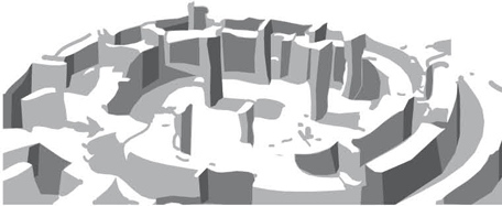
9000 BC: Göbekli Tepe (Turkey). The world’s oldest known stone temples.
Neolithic Age: China, Northern Shaanxi province. Cave dwelling continues to the present day.
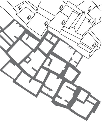
7500 BC: Catal Hüyük (Anatolia). Mud-brick houses with plastered interior walls.
6500 BC: Mehrgarh (Pakistan). Compartmentalized mud-brick structures.
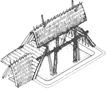
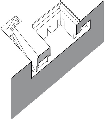
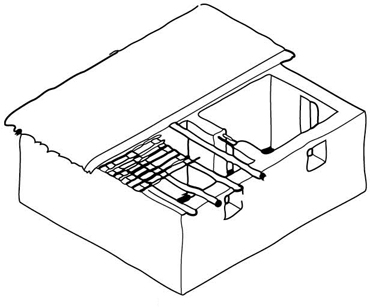
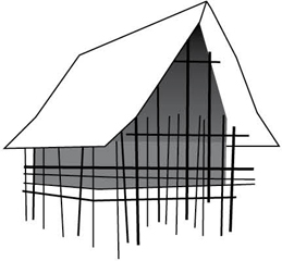
5000 BC: Banpo, China. Pit-style houses using thick pillars to support their roofs.
3000 BC: Alvastra (Scandinavia). Houses raised on wood stilts.
3000 BC: Egyptians mix straw with mud to bind dried bricks.

2600 BC: Harappa and Mohenjo-daro, Indus Valley, modern-day Pakistan and India. Fire-baked bricks and corbeled arches.
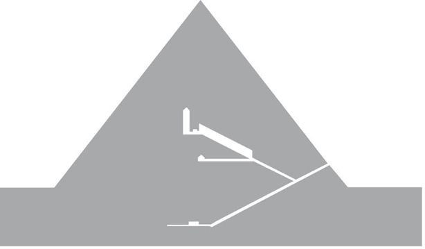
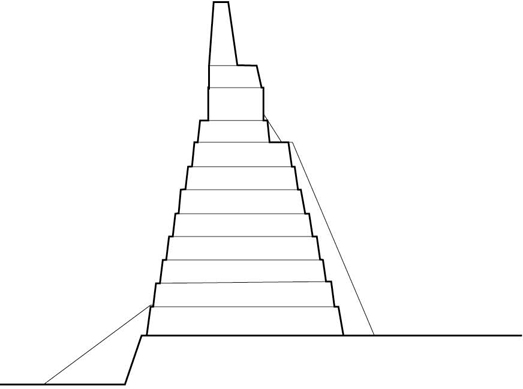
2500 BC: Great Pyramid of Khufu, Egypt. Until the 19th century, this stone pyramid was the tallest structure in the world.
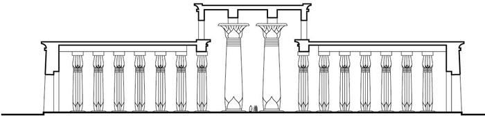
1500 BC: Temple of Amun at Karnak, Egypt. Hypostyle Hall is a stellar example of trabeated (column-and-beam) stone construction.
12th century BC: Zhou Dynasty architecture. Corbel brackets (dougong) on column heads help support projecting eaves.
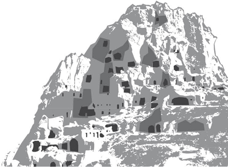
1000 BC: Cappadocia, Anatolia. Extensive excavations formed houses, churches, and monasteries.
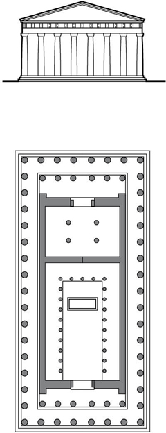
447 BC: Parthenon, Athens. This Temple of Athena is considered to be a paragon of the Doric order.
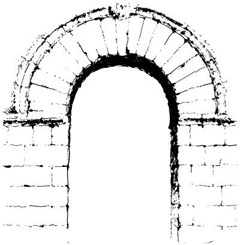
4th century BC: Etruscans develop the masonry arch and vault. Porta Pulchra, Perugia.
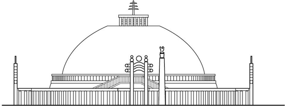
3rd century BC: Great Stupa at Sanchi, India. Carved stone Buddhist monument.
200 BC: India. Numerous examples of Buddhist, Jain, and Hindu cave architecture.
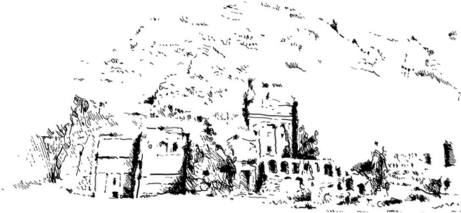
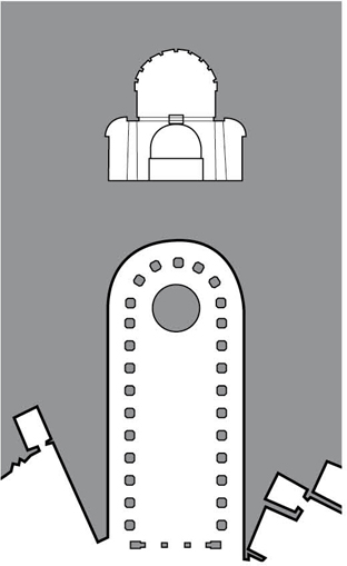
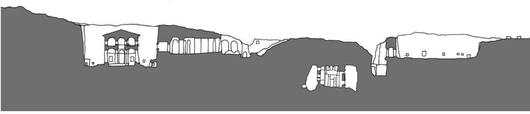
10 BC: Petra, Jordan. Palace tombs half-built, half-carved into the rock.

70 AD: Colosseum, Rome. Stone-faced brick and concrete amphitheater.
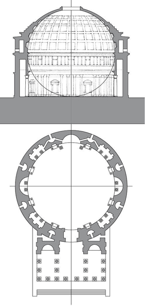
125 AD: The Pantheon, Rome. Coffered concrete dome largest in the world until 18th century.
3rd century AD: Tikal (Guatemala). Mayan city of stone pyramids and palaces.
460 AD: Yungang Grottoes, China. Buddhist temples carved into sandstone cliffs.

532–37 AD: Hagia Sophia, Istanbul. Central dome carried on pendentives that enable the transition from round dome to square plan. Concrete is used in the construction of the vaulting and arches of the lower levels.
7th century AD: Tang Dynasty architecture. Earthquake-resistant timber framework comprised columns, beams, purlins, and a multitude of corbel brackets.
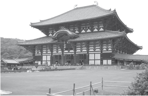
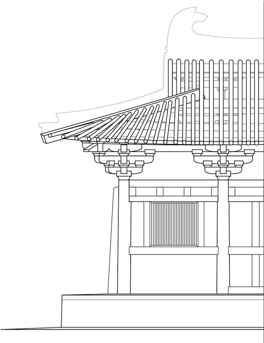
752 AD: Todaiji, Nara. Buddhist temple is world’s largest wooden building; present reconstruction is two-thirds of the original temple’s size.
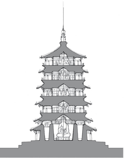
1056: Sakyamuni Pagoda, China. Oldest surviving timber pagoda and tallest timber building in the world at a height of 220 feet (67.1 m).
11th century: Abbey church of St-Philibert, Tournus. Unadorned cylindrical pillars more than 4 feet (1.2 m) thick support the spacious and light nave.
1100: Chan Chan. Citadel walls of stucco-covered mud-brick.
1100: Lalibela, Ethiopia. Site of monolithic, rock-cut churches.
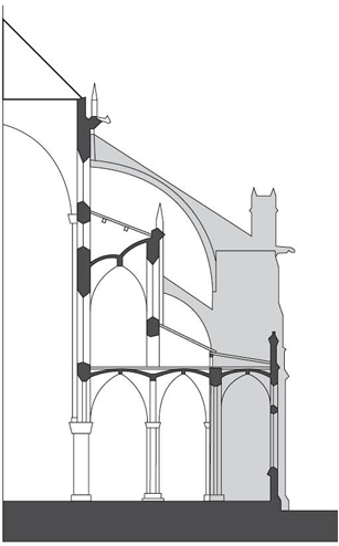
1163–1250: Notre Dame Cathedral, Paris. Cut stone structure utilizes external flying buttresses to transmit the outward and downward thrust from a roof or vault to a solid buttress.
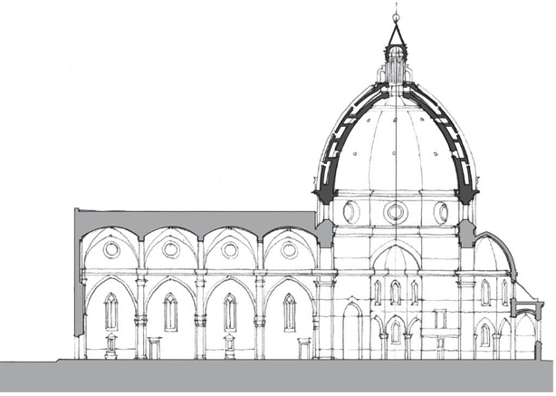
13th century: Cathedral of Florence, Italy. Filippo Brunelleschi designed the double-walled dome, resting on a drum, to allow it to be built without the need for scaffolding from the ground.
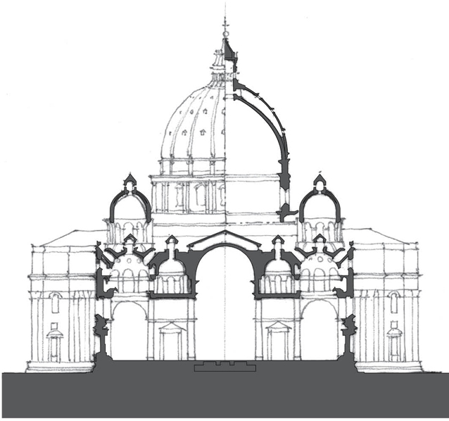
1506–1615: St. Peter’s Basilica, Rome, Donato Bramante, Michelangelo, Giacomo della Porta. Until recently the largest church ever built, covering an area of 5.7 acres (23,000 m2).
1638: Galileo publishes his first book, The Discourses and Mathematical Demonstrations Relating to Two New Sciences, the two sciences referring to the strength of materials and the motion of objects.
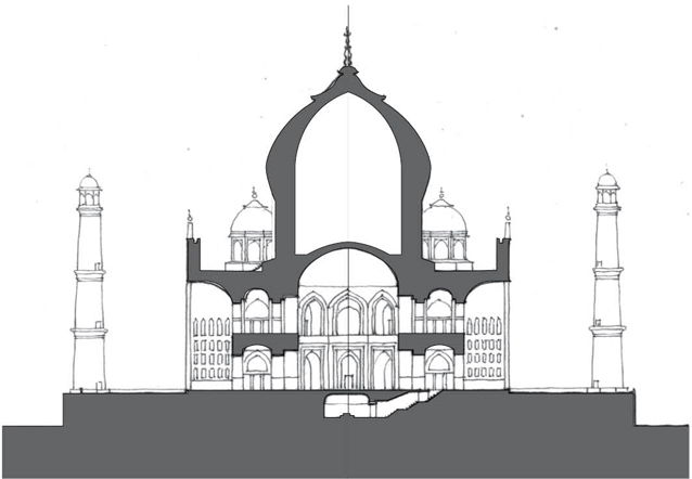
1653: Taj Mahal, Agra, India. Ahmad Lahauri. Iconic white-domed, marble mausoleum built in memory of Mumtaz Mahai, wife of Mughal Emperor Shah Jahan.
1777–79: Iron Bridge at Coalbrookdale, England. T. M. Pritchard.
1797: Ditherington Flax Mill, Shrewsbury, England, William Strutt. Oldest steel-framed building in the world, having a structural frame of cast iron columns and beams.

1851: Crystal Palace, Hyde Park, London, John Paxton. Prefabricated units of wrought iron and glass were assembled to create 990,000 square feet (91,974 m2) of exhibition space.
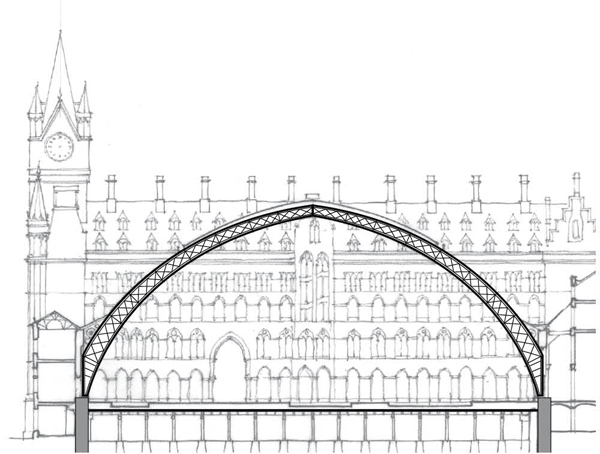
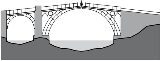
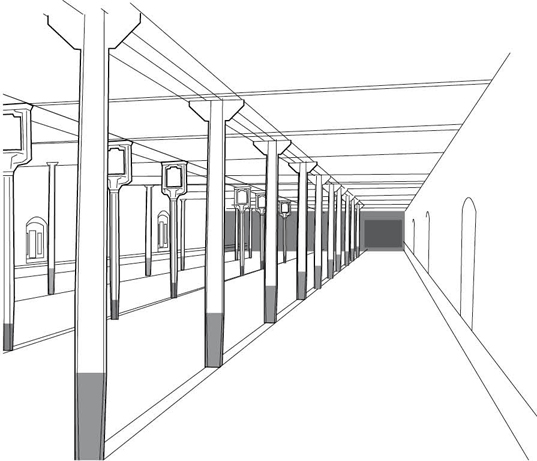
1868: St. Pancras Station, London, William Barlow. Trussed arch structure with tie rods below floor level to resist outward thrust.
1881: Charles Louis Strobel standardizes rolled wrought-iron sections and riveted connections.
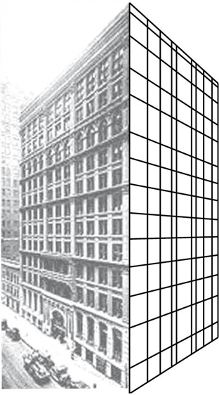
1884: Home Insurance Building, Chicago, William Le Baron Jenney. The 10-story structural frame of steel and cast iron carries the majority of the weight of the floors and exterior walls.
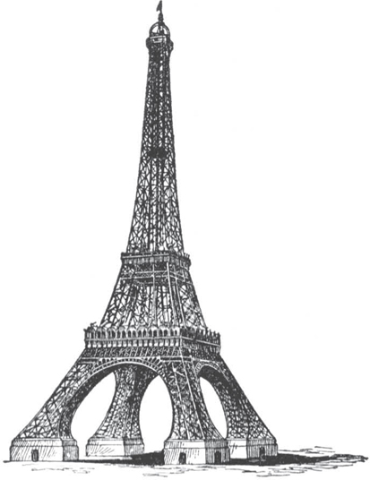
1889: Eiffel Tower, Paris, Gustave Eiffel. The Tower replaced the Washington Monument as the world’s tallest structure, a title it retained until the Chrysler Building in New York City was erected in 1930.
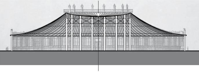
1896: Rotunda-Pavilion, All-Russia Industrial and Art Exhibition, Nizhny Novgorod, Vladimir Shukhov. The world’s first steel tensile structure.
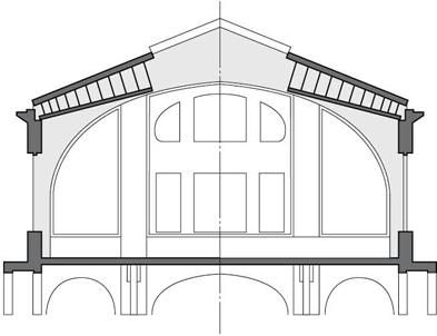
1898: Public Natatorium, Gebweiler, France, Eduard Züblin. Reinforced concrete roof vault consists of five rigid frames with thin plates spanning between each frame.
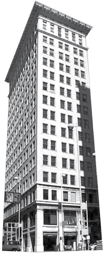
1903: Ingalls Building, Cincinnati, Ohio, Elzner & Anderson. First reinforced concrete high-rise building.
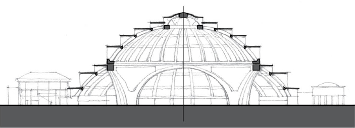
1913: Jahrhunderthalle (Centennial Hall), Breslau, Max Berg. Reinforced concrete structure, including a 213-feet (65-m) diameter dome, influences the use of concrete for enclosing large, public spaces.

1922: Planetarium, Jena, Germany, Walter Bauerfeld. First contemporary geodesic dome on record, derived from the icosahedron.
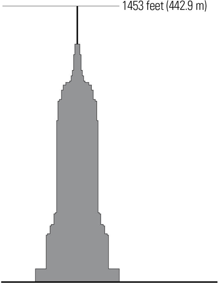
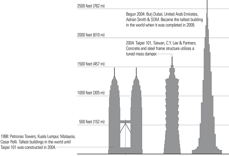
1931: Empire State Building, New York City, Shreve, Lamb, and Harmon. World’s tallest building until 1972.

1943–59: Guggenheim Museum, New York City, Frank Lloyd Wright.

1960: Palazzo Dello Sport, Rome, Italy, Pier Luigi Nervi. 330-feet (100-m) diameter ribbed reinforced-concrete dome built for the 1960 Summer Olympic Games.
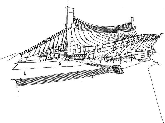
1961: Olympic Arena, Tokyo, Kenzo Tange. World’s largest suspended roof structure when built, its steel cables are suspended from two reinforced concrete pillars.
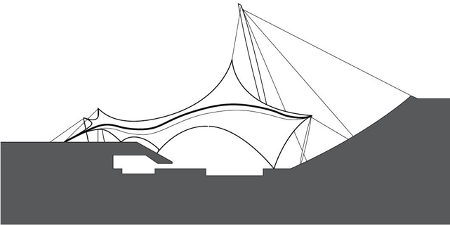
1972: Olympic Swimming Arena, Munich, Germany, Frei Otto. Steel cables combine with fabric membranes to create an extremely lightweight, long-span structure.
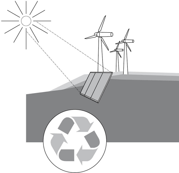
1973: Rise in oil prices stimulates research into alternative sources of energy, leading to energy conservation becoming a major element in architectural design.
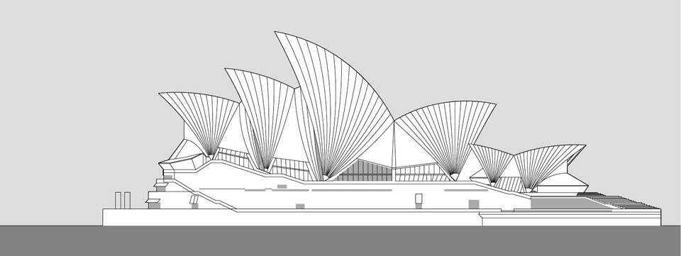
1973: Sydney Opera House, Jørn Utzon. Iconic shell structures consist of prefabricated, cast-on-site concrete ribs.
ARCHITECTURAL STRUCTURES
The preceding historical review conveys a sense not only of how structural systems have evolved but also how they have had, and will continue to have, an impact on architectural design. Architecture embodies ineffable yet sensible, aesthetic qualities that emerge from a union of space, form, and structure. In providing support for other building systems and our activities, a structural system enables the shape and form of a building and its spaces, similar to the way in which our skeletal system gives shape and form to our body and support to its organs and tissues. So when we speak of architectural structures, we refer to those that unite with form and space in a coherent manner.
Designing an architectural structure therefore involves more than the proper sizing of any single element or component, or even the design of any particular structural assembly. It is not simply the task of balancing and resolving forces. Rather, it requires that we consider the manner in which the overall configuration and scale of structural elements, assemblies, and connections encapsulate an architectural idea, reinforce the architectural form and spatial composition of a design proposal, and enable its constructibility. This then requires an awareness of structure as a system of interconnected and interrelated parts, an understanding of the generic types of structural systems, as well as an appreciation for the capabilities of certain types of structural elements and assemblies.

To understand the impact of structural systems on architectural design, we should be aware of how they relate to the conceptual, experiential, and contextual ordering of architecture.
- Formal and spatial composition
- Definition, scale, and proportions of forms and spaces
- Qualities of shape, form, space, light, color, texture, and pattern
- Ordering of human activities by their scale and dimension
- Functional zoning of spaces according to purpose and use
- Access to and the horizontal and vertical paths of movement through a building
- Buildings as integral components within the natural and built environment
- Sensory and cultural characteristics of place
The remaining sections of this chapter outline major aspects of structural systems that support, reinforce, and ultimately give form to an architectural idea.
Formal Intent
There are three fundamental ways in which the structural system can relate to the form of an architectural design. These fundamental strategies are:
- Exposing the structural system
- Concealing the structure
- Celebrating the structure

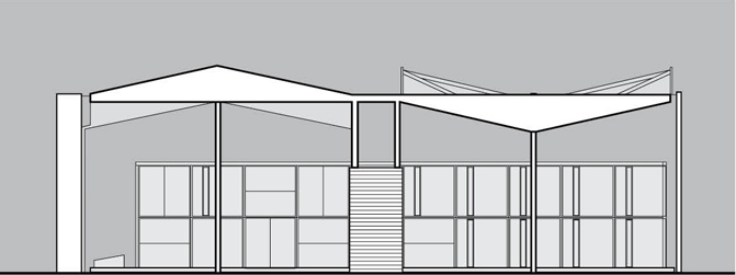
Exposing the Structure
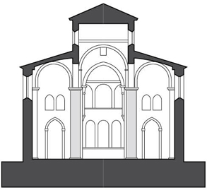
Historically, stone- and masonry-bearing wall systems dominated architecture until the advent of iron and steel construction in the late-18th century. These structural systems also functioned as the primary system of enclosure and therefore expressed the form of the architecture, typically in an honest and straightforward manner.
Whatever formal modifications were made were usually a result of molding or carving the structural material in such a way as to create additive elements, subtractive voids, or reliefs within the mass of the structure.
Even in the modern era, there are examples of buildings that exposed their structural systems—whether in timber, steel, or concrete—using them effectively as the primary architectonic form-givers.
SS. Sergius and Bacchus, Istanbul, Turkey, 527–536 AD. The Ottomans converted this Eastern Orthodox church into a mosque. Featuring a central dome plan, it is believed by some to be a model for Hagia Sophia.
Centre Le Corbusier/Heidi Weber Pavilion, Zurich, 1965, Le Corbusier. A structural steel parasol hovers over a modular steel frame structure with sides of enameled steel panels and glass.
Concealing the Structure
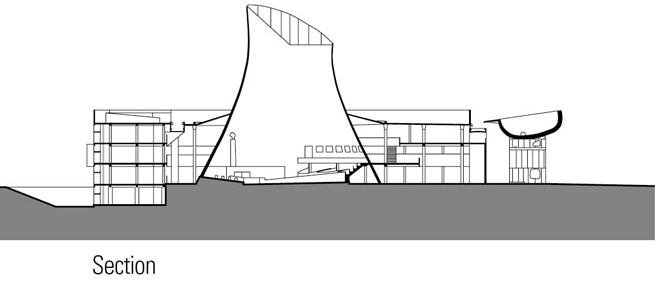
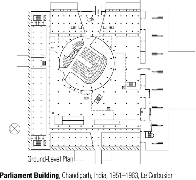
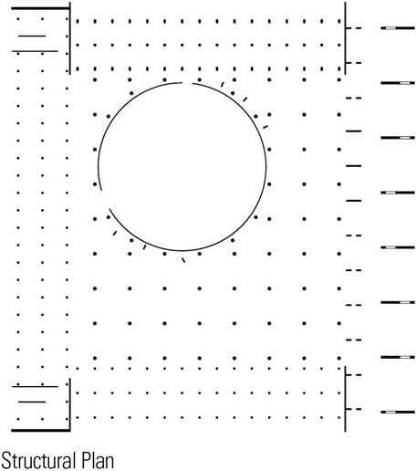
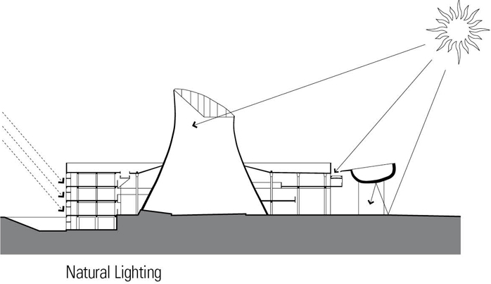
In this strategy, the structural system is concealed or obscured by the exterior cladding and roofing of the building. Some reasons for concealing the structure are practical, as when the structural elements must be clad to make them fire-resistant, or contextual, as when the desired exterior form is at odds with interior space requirements. In the latter case, the structure may organize the interior spaces while the form of the exterior shell responds to site conditions or constraints.
The designer may simply want freedom of expression for the shell without considering how the structural system might aid or hinder formal decisions. Or the structural system may be obscured through neglect rather than intent. In both of these cases, legitimate questions arise as to whether the resulting design is intentional or accidental, willful or, dare we say, careless.
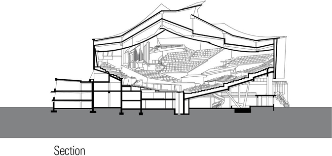
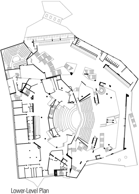
Philharmonic Hall, Berlin, Germany, 1960–63, Hans Scharoun. An example of the Expressionist movement, this concert hall has an asymmetric structure with a tent-like concrete roof and a stage in the middle of terraced seating. Its external appearance is subordinate to the functional and acoustic requirements of the concert hall.
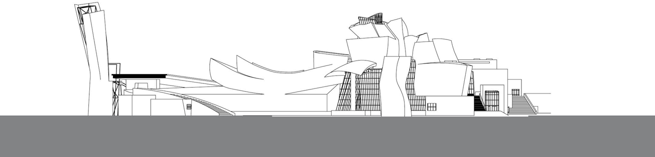
Guggenheim Museum, Bilbao, Spain, 1991–97, Frank Gehry. A novelty when completed, this contemporary art museum is known for its sculpted, titanium-clad forms. While difficult to understand in traditional architectural terms, the definition and constructibility of the apparently random forms were made possible through the use of CATIA, an integrated suite of Computer Aided Design (CAD), Computer Aided Engineering (CAE), and Computer Aided Manufacturing (CAM) applications.
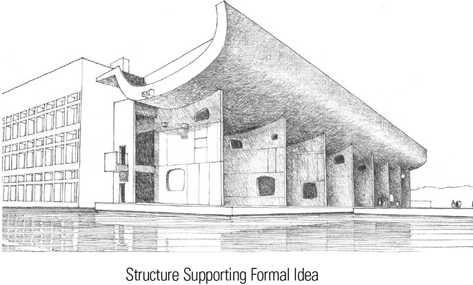
Celebrating the Structure
Rather than being merely exposed, the structural system can be exploited as a design feature, celebrating the form and materiality of the structure. The often exuberant nature of shell and membrane structures makes them appropriate candidates for this category.
There are also those structures that dominate by the sheer forcefulness with which they express the way they resolve the forces acting on them. These types of structures often become iconic symbols due to their striking imagery. Think Eiffel Tower or the Sydney Opera House.
When judging whether a building celebrates its structure or not, we should be careful to differentiate structural expression from expressive forms which are not, in truth, structural but only appear to be so.
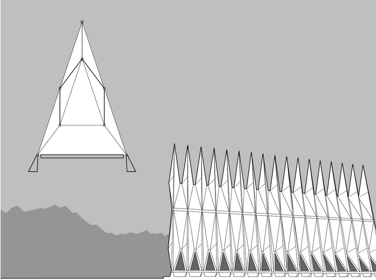
Air Force Academy Chapel, Colorado Springs, Colorado, USA, 1956–62, Walter Netsch/Skidmore, Owings and Merrill. The soaring structure, consisting of 100 identical tetrahedrons, develops stability through the triangulation of individual structural units as well as a triangular section.

Los Manantiales, Xochimilco, Mexico, 1958, Felix Candela. The thin-shell concrete structure consists of a series of intersecting, saddle-shaped hyperbolic paraboloids arranged in a radial plan.
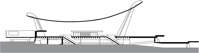
Main Terminal, Dulles International Airport, Chantilly, Virginia, USA, 1958–62, Eero Saarinen. Catenary cables suspended between two long colonnades of outward- leaning and tapered columns carry a gracefully curved concrete roof suggestive of flight.
Hong Kong and Shanghai Bank, Hong Kong, China, 1979–85, Norman Foster. Eight groups of four aluminum-clad steel columns rise up from the foundations and support five levels of suspension trusses, from which are hung the floor structures.

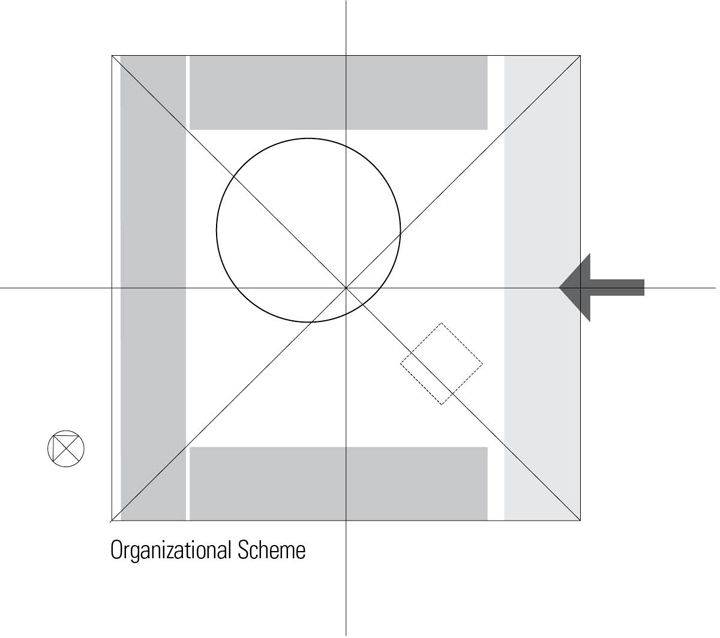
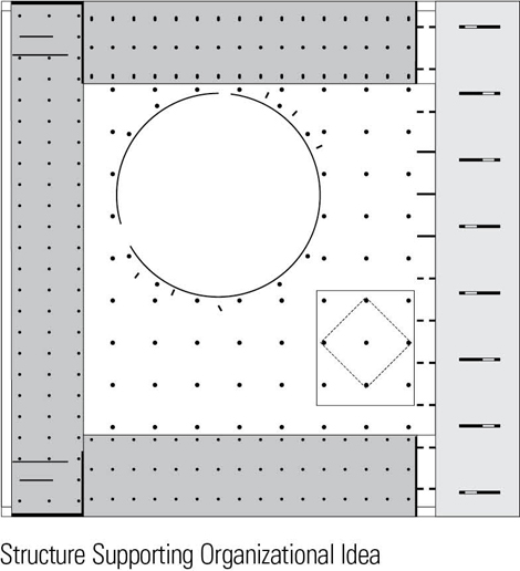
Spatial Composition
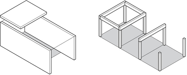
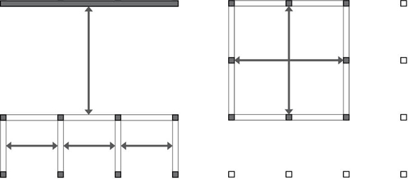
The form of a structural system and the pattern of its supporting and spanning elements can be related to the spatial layout and composition of a design in two fundamental ways. The first is a correspondence between the form of the structural system and that of the spatial composition. The second is a looser fit in which the structural form and pattern allow more freedom or flexibility in spatial layout.
Correspondence
Where there is a correspondence between structural form and spatial composition, either the pattern of structural supports and spanning systems can prescribe the disposition of spaces within a building or the spatial layout can suggest a certain type of structural system. In the design process, which comes first?
In ideal cases, we consider both space and structure together as co-determinants of architectural form. But composing spaces according to needs and desires often precedes thinking about structure. On the other hand, there are times when structural form can be the driving force in the design process.
In either case, structural systems that prescribe a pattern of spaces of certain sizes and dimensions, or even a pattern of use, may not allow for flexibility in future use or adaptation.
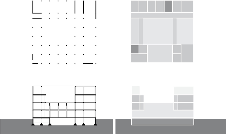
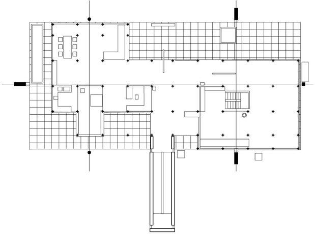
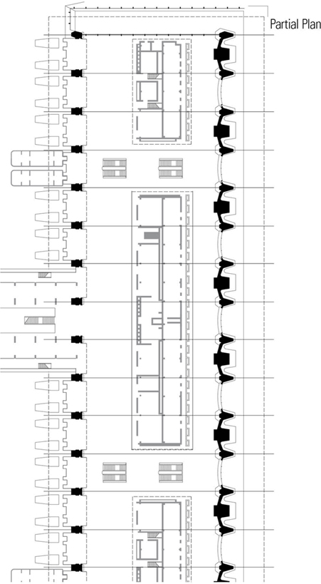
Structural and Spatial Diagrams in Plan and Section. Casa del Fascio, Como, Italy, 1932–36, Giuseppe Terragni.
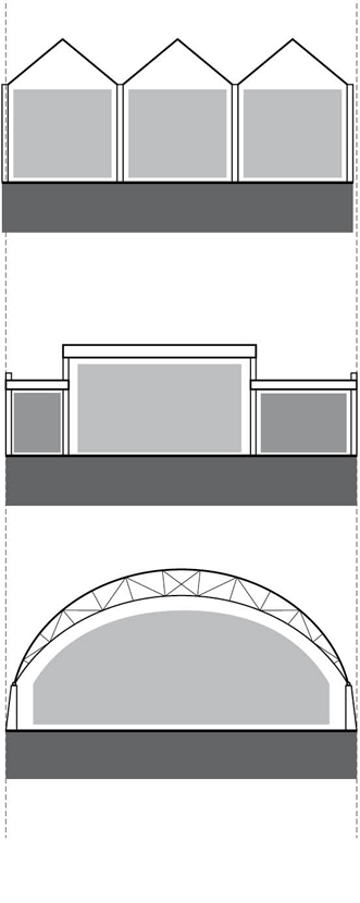
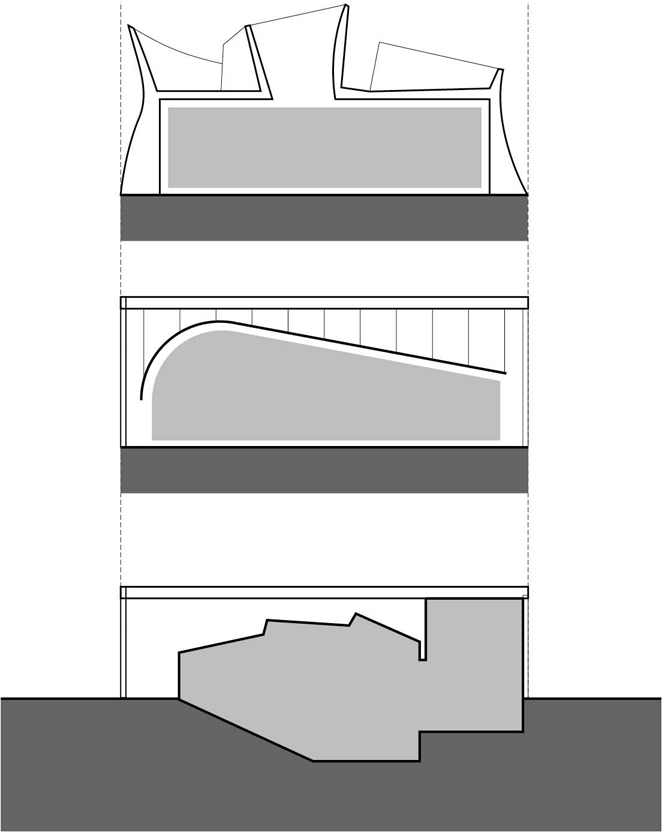
Contrast
When there is a lack of correspondence between structural form and spatial composition, either may take precedence. The structure may be large enough to shelter or encompass a series of spaces within its volume, or the spatial composition may dominate a concealed structure. An irregular or asymmetrical structural system may envelop a more regular spatial composition, or a structural grid may provide a uniform set or network of points against which a freer spatial composition can be gauged or contrasted.
A distinction between space and structure may be desirable to provide flexibility of layout; allow for growth and expansion; make visible the identity of different building systems; or express differences between interior and exterior needs, desires, and relationships.
STRUCTURAL SYSTEMS
A system can be defined as an assembly of interrelated or interdependent parts forming a more complex and unified whole and serving a common purpose. A building can be understood to be the physical embodiment of a number of systems and subsystems that must necessarily be related, coordinated, and integrated with each other as well as with the three-dimensional form and spatial organization of the building as a whole.
The structural system of a building, in particular, consists of a stable assembly of structural elements designed and constructed to support and transmit applied loads safely to the ground without exceeding the allowable stresses in the members. Each of the structural members has a unitary character and exhibits a unique behavior under an applied load. But before individual structural elements and members can be isolated for study and resolution, it is important for the designer to understand how the structural system accommodates and supports in a holistic manner the desired programmatic and contextual forms, spaces, and relationships of an architectural scheme.
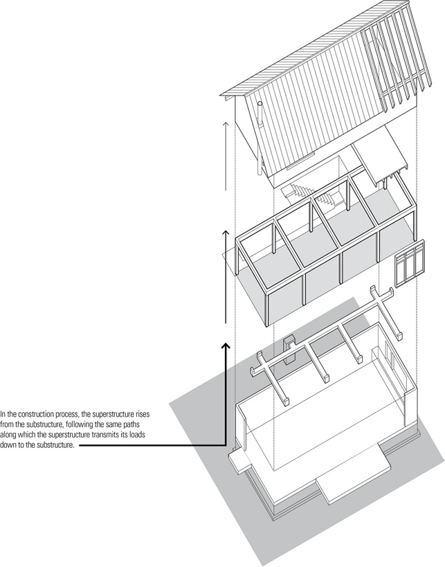
Regardless of the size and scale of a building, it comprises physical systems of structure and enclosure that define and organize its forms and spaces. These elements can be further categorized into a substructure and a superstructure.
Substructure
The substructure is the lowest division of a building—its foundation—constructed partly or wholly below the surface of the ground. Its primary function is to support and anchor the superstructure above and transmit its loads safely into the earth. Because it serves as a critical link in the distribution and resolution of building loads, the foundation system, while normally hidden from view, must be designed to both accommodate the form and layout of the superstructure above and respond to the varying conditions of soil, rock, and water below.
The principal loads on a foundation are the combination of dead and live loads acting vertically on the superstructure. In addition, a foundation system must anchor the superstructure against wind-induced sliding, overturning, and uplift, withstand the sudden ground movements of an earthquake, and resist the pressure imposed by the surrounding soil mass and groundwater on basement walls. In some cases, a foundation system may also have to counter the thrust from arched or tensile structures.

An important influence on the type of substructure we select, and consequently, the structural pattern we design, is the site and context for a building.
- Relation to superstructure: The type and pattern of required foundation elements impact, if not dictate, the layout of supports for the superstructure. Vertical continuity in load transmission should be maintained as much as possible for structural efficiency.
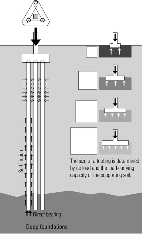
- Soil type: The integrity of a building structure depends ultimately on the stability and strength under loading of the soil or rock underlying the foundation. The bearing capacity of the underlying soil or rock may therefore limit the size of a building or require deep foundations.
- Relation to topography: The topographic character of a building site has both ecological and structural implications and consequences, requiring that any site development be sensitive to natural drainage patterns, conditions conducive to flooding, erosion, or slides, and provisions for habitat protection.
Shallow Foundations
Shallow or spread foundations are employed when stable soil of adequate bearing capacity occurs relatively near to the ground surface. They are placed directly below the lowest part of a substructure and transfer building loads directly to the supporting soil by vertical pressure. Shallow foundations can take any of the following geometric forms:
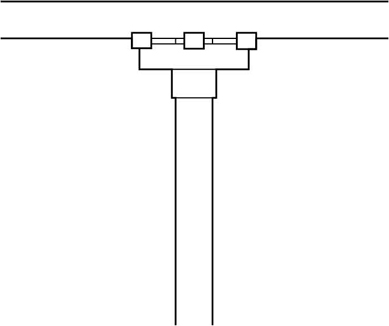
- Point: Column footings
- Line: Foundation walls and footings
- Plane: Mat foundations—thick, heavily reinforced concrete slabs that serve as a single monolithic footing for a number of columns or an entire building—are used when the allowable bearing capacity of a foundation soil is low relative to building loads and interior column footings become so large that it becomes more economical to merge them into a single slab. Mat foundations may be stiffened by a grid of ribs, beams, or walls.

Deep Foundations
Deep foundations consist of caissons or piles that extend down through unsuitable soil to transfer building loads to a more appropriate bearing stratum of rock or dense sands and gravels well below the superstructure.
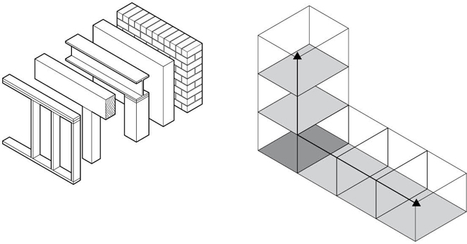
Superstructure
The superstructure, the vertical extension of a building above the foundation, consists of a shell and interior structure that defines the form of a building and its spatial layout and composition.
Shell
The shell or envelope of a building, consisting of the roof, exterior walls, windows, and doors, provides protection and shelter for the interior spaces of a building.
- The roof and exterior walls shelter interior spaces from inclement weather and control moisture, heat, and air flow through the layering of construction assemblies.
- Exterior walls and roofs also dampen noise and provide security and privacy for the occupants of a building.
- Doors provide physical access.
- Windows provide access to light, air, and views.
Structure
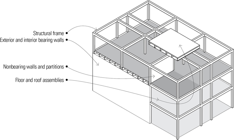
A structural system is required to support the shell of a building as well as its interior floors, walls, and partitions, and to transfer the applied loads to the substructure.
- Columns, beams, and loadbearing walls support floor and roof structures.
- Floor structures are the flat, level base planes of interior space that support our interior activities and furnishings.
- Interior structural walls and nonloadbearing partitions subdivide the interior of a building into spatial units.
- Lateral-force-resisting elements are laid out to provide lateral stability.
The formal intent of an architectural design may be offered, given, suggested, or mandated by the site and context, the program and function, or by purpose and meaning. Concurrent with thinking about formal and spatial options, we should also begin to consider our structural options—the palette of materials, the types of support, spanning, and lateral-force-resisting systems—and how these choices might influence, support, and reinforce the formal and spatial dimensions of a design idea.
At a later stage in the design process, it will also be necessary to investigate the shaping and sizing of members and detailing of connections, but the aforementioned large-scale decisions should take precedence because they ultimately determine the direction of and set the parameters for design and detail development.
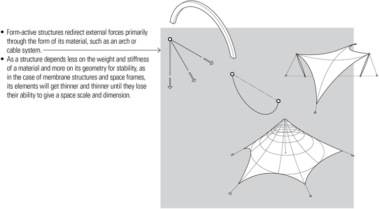
Types of Structural Systems
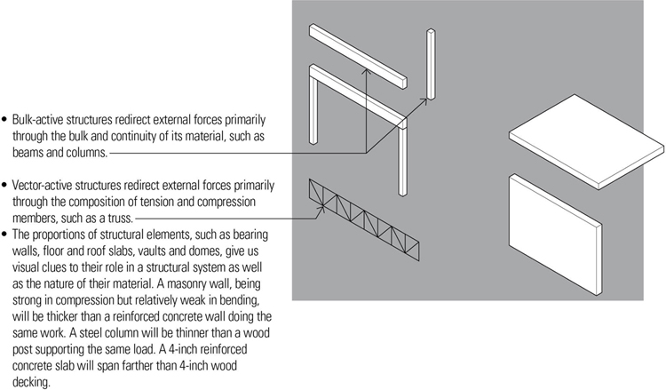
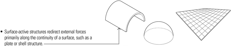
Given a specific attitude toward the expressive role of the structural system and the desired spatial composition, appropriate choices for a structural system can be made if one understands the formal attributes the various systems develop in responding to applied forces and redirecting these forces to their foundations.
Structural Analysis and Design
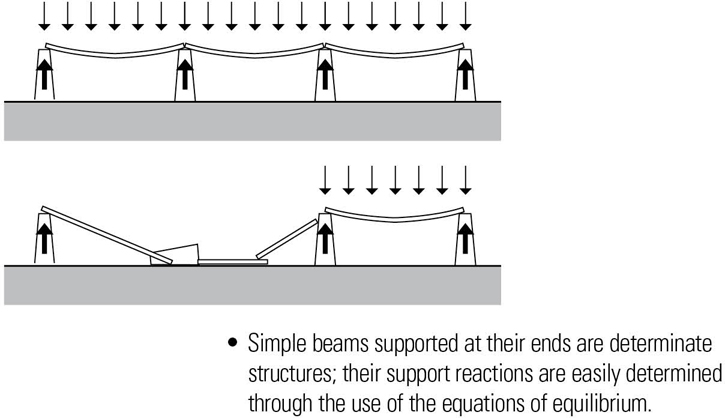
Before proceeding to a discussion of structural design, it might be useful to distinguish between structural design and structural analysis. Structural analysis is the process of determining the ability of a structure or any of its constituent members, either existing or assumed, to safely carry a given set of loads without material distress or excessive deformation, given the arrangement, shape, and dimensions of the members, the types of connections and supports utilized, and the allowable stresses of the materials employed. In other words, structural analysis can occur only if given a specific structure and certain load conditions.
Structural design, on the other hand, refers to the process of arranging, interconnecting, sizing, and proportioning the members of a structural system in order to safely carry a given set of loads without exceeding the allowable stresses of the materials employed. Structural design, similar to other design activities, must operate in an environment of uncertainty, ambiguity, and approximation. It is a search for a structural system that can meet not only the load requirements but also address the architectural, urban design, and programmatic issues at hand.
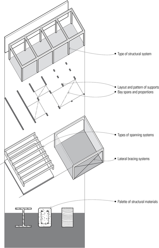
The first step in the structural design process may be stimulated by the nature of the architectural design, its site and context, or the availability of certain materials.
- The architectural design idea may elicit a specific type of configuration or pattern.
- The site and context may suggest a certain type of structural response.
- Structural materials may be dictated by building code requirements, supply, availability of labor, or costs.
Once the type of structural system, its configuration or pattern, and the palette of structural materials are projected, then the design process can proceed to the sizing and proportioning of assemblies and individual members and the detailing of connections.
- For clarity, lateral-force-resisting elements have been omitted. See Chapter 5 for lateral-force-resisting systems and strategies.

Detailing of Connections
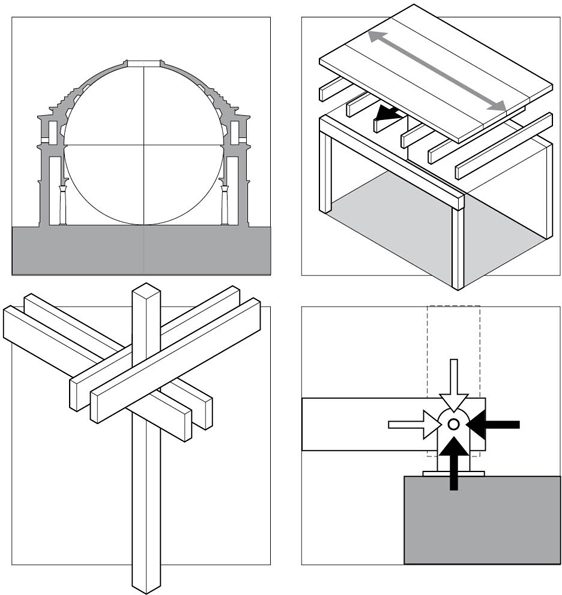
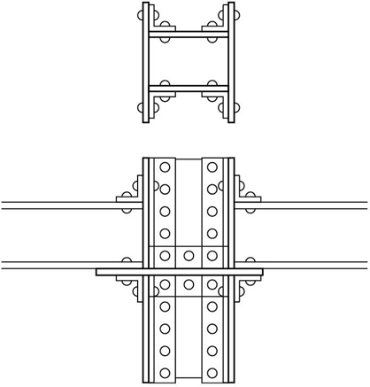
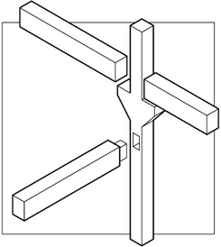
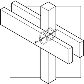
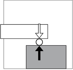
The manner in which forces are transferred from one structural element to the next and how a structural system performs as a whole depend to a great extent on the types of joints and connections used. Structural elements can be joined to each other in three ways.
- Butt joints allow one of the elements to be continuous and usually require a third mediating element to make the connection.
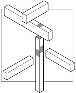
- Overlapping joints allow all of the connected elements to bypass each other and be continuous across the joint.
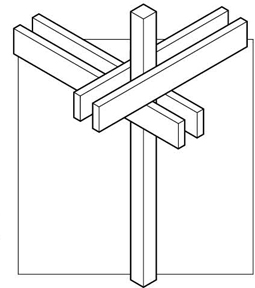
- The joining elements can also be molded or shaped to form a structural connection.
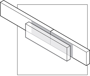
We can also categorize structural connections on a geometric basis.
- Point: bolted connections
- Line: welded connections
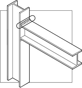
- Plane: glued connections
There are four fundamental types of structural connections.
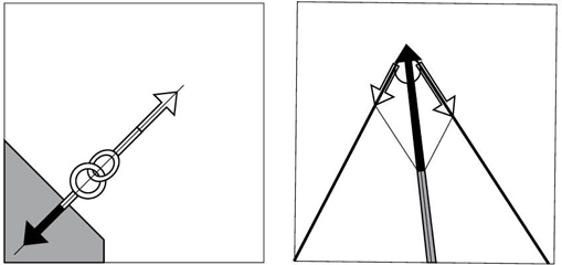
- Pin or hinge joints allow rotation but resist translation in any direction.
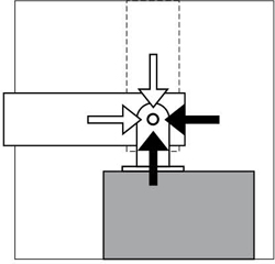
- Roller joints or supports allow rotation but resist translation in a direction perpendicular into or away from its face.
- Rigid or fixed joints maintain the angular relationship between the joined elements, restrain rotation and translation in any direction, and provide both force and moment resistance.
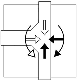
- Cable supports or anchorages allow rotation but resist translation only in the direction of the cable.
STRUCTURAL PLANNING
In the design process, we tend to think first of the larger holistic pattern before we consider the elemental structural units that make up the larger whole. So as we strategize to develop a structural plan for a building, we should consider both the essential qualities of the architectural composition and the nature and configuration of the structural elements. This leads to a series of fundamental questions:
Building Design
- Is there an overarching form required or does the architectural composition consist of articulated parts? If so, are these parts to be hierarchically ordered?
- Are the principal architectural elements planar or linear in nature?

Building Program
- Are there required relationships between the desirable scale and proportion of the program spaces, the spanning capability of the structural system, and the resulting layout and spacing of supports?
- Is there a compelling spatial reason for one-way or two-way spanning systems?
Systems Integration
- How might the mechanical and other building systems be integrated with the structural system?
Code Requirements
- What are the building code requirements for the intended use, occupancy, and scale of building?
- What is the type of construction and what are the structural materials required?
Economic Feasibility
- How might material availability, fabrication processes, transportation requirements, labor and equipment requirements, and erection time influence the choice of a structural system?
- Is there a need to allow for expansion and growth either horizontally or vertically?
Legal Constraints
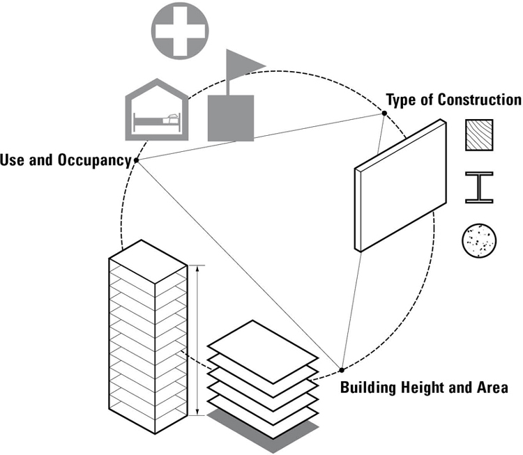
There exists a regulated relationship between the size (height and area) of a building and its intended use, occupancy load, and type of construction. Understanding the projected scale of a building is important because a building’s size is related to the type of structural system required and the materials that may be employed for its structure and construction.
Zoning Ordinances
Zoning ordinances constrain the allowable bulk (height and area) and shape of a building based on its location in a municipality and position on its site, usually by specifying various aspects of its size.
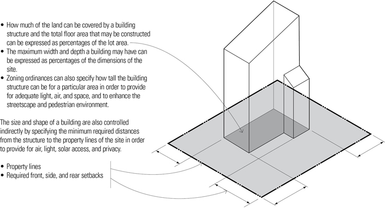
Building codes specify the fire-resistance ratings of materials and construction required for a building, depending on its location, use and occupancy, and height and area per floor.
Building Height and Area
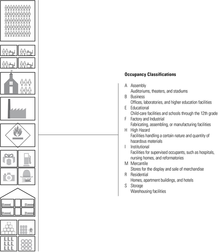
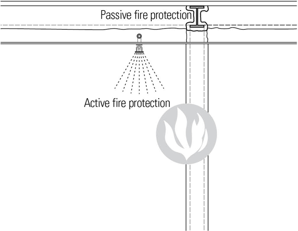
In addition to zoning ordinances that may limit the use and the overall floor area, height, and bulk of a building, building codes, such as the International Building Code® (IBC), limit the maximum height and area per floor of a building according to construction type and occupancy group, expressing the intrinsic relationship between degree of fire resistance, size of a building, and nature of an occupancy. The larger a building, the greater the number of occupants, and the more hazardous the occupancy, the more fire-resistant the structure should be. The intent is to protect a building from fire and to contain a fire for the time required to safely evacuate occupants and for a firefighting response to occur. The limitation on size may be exceeded if the building is equipped with an automatic fire sprinkler system, or if it is divided by fire walls into areas not exceeding the size limitation.
Maximum Height and Area
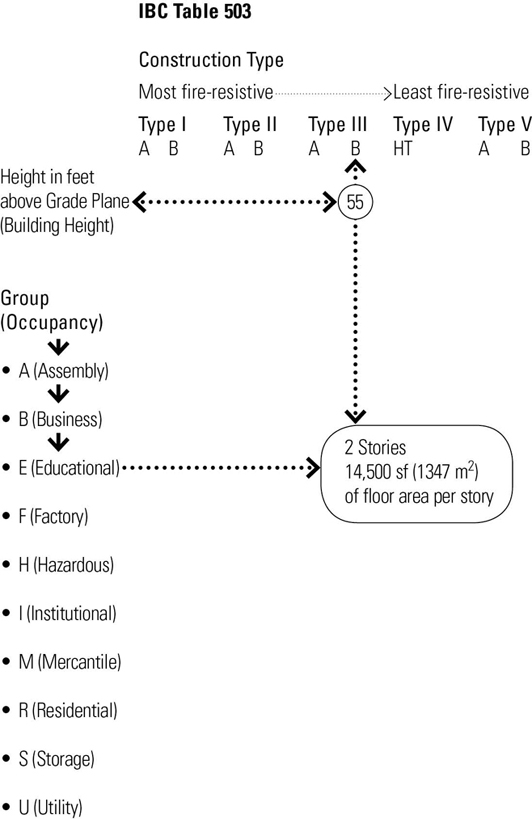
In IBC Table 503, the allowable height and area of a building are determined by the intersection of occupancy group and construction type. As occupancy is usually determined before heights and areas, the table will typically be entered by reading down the list of occupancy groups to find the occupancy that fits the building design. Reading across leads to the allowable heights and building areas based on types of construction.
Note that the distinction between A and B categories of construction types is one of level of fire resistance. Because category A is of higher fire resistance, Type A buildings of any construction type have higher allowable heights and areas than Type B buildings. Using the principle of classifying occupancies by degree of hazard and building types by fire-resistance, the higher the level of fire and life safety, the larger and taller a building can be.
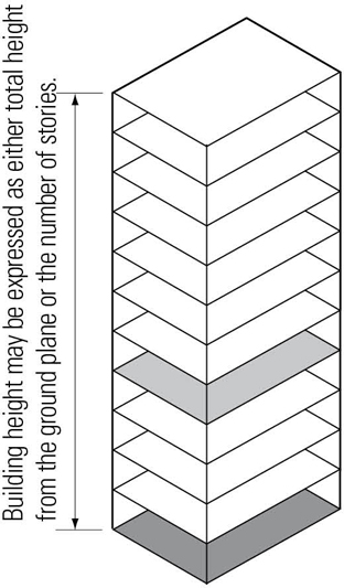
Heights are expressed in two ways. The first is height in feet above the grade plane and is generally independent of occupancy, but tied to fire-resistance; the second is height in stories and is tied to occupancy. Both sets of criteria apply to each analysis. This is to avoid having high floor-to-floor heights between stories that could generate a building exceeding the height limit in feet above grade plane if heights were not also tabulated.
The chart that follows will show the relationship of occupancy and construction type to allowable heights and building areas. The examples highlight the differences as one proceeds from Type I fire-protected construction to Type V unrated construction.
Excerpt from IBC Table 503 (Showing allowable building height, number of stories and proportionate floor areas per story)

Types of Construction
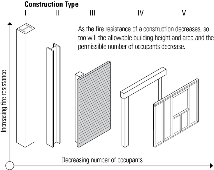
The IBC classifies the construction of a building according to the fire resistance of its major elements:
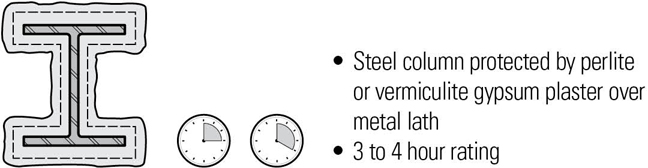
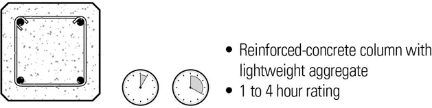
- Type I buildings have their major building elements constructed of noncombustible materials, such as concrete, masonry, or steel. Some combustible materials are allowed if they are ancillary to the primary structure of the building.
- Type II buildings are similar to Type I buildings except for a reduction in the required fire-resistance ratings of the major building elements.
- Type III buildings have noncombustible exterior walls and major interior elements of any material permitted by the code.
- Type IV buildings (Heavy Timber, HT) have noncombustible exterior walls and major interior elements of solid or laminated wood of specified minimum sizes and without concealed spaces.
- Type V buildings have structural elements, exterior walls, and interior walls of any material permitted by the code.
- Protected construction requires all major building elements, except for nonbearing interior walls and partitions, to be of one-hour fire-resistive construction.
- Unprotected construction has no requirements for fire-resistance except for when the code requires protection of exterior walls due their proximity to a property line.

Required Fire-Resistance Ratings in Hours (Based on IBC Table 601)
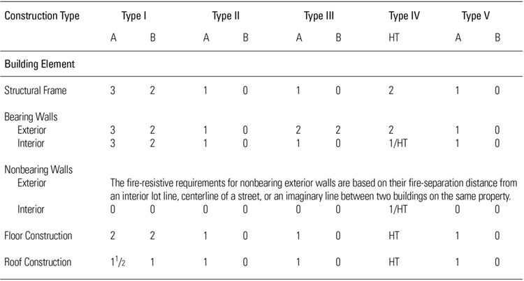
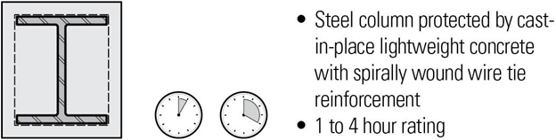
Fire-resistance ratings are based on the performance of various materials and construction assemblies under fire-test conditions as defined by the American Society for Testing and Materials (ASTM). However, the building code allows designers to use several alternate methods to demonstrate compliance with fire-resistive criteria. One method allows the use of ratings determined by such recognized agencies as Underwriters Laboratory or Factory Mutual. The International Building Code itself contains a listing of prescriptive assemblies, which describe the protective measures that can be applied to structural members, to floor and roof construction, and to walls to achieve the necessary ratings.
In planning any structural system, there are two attributes that should be built into the design, guide its development, and ensure its stability, durability, and efficiency. These attributes—redundancy and continuity—apply not to a specific material or to an individual type of structural member, such as a beam, column, or truss, but rather to a building structure viewed as a holistic system of interrelated parts.
The failure of a building structure can result from any fracturing, buckling, or plastic deformation that renders a structural assembly, element, or joint incapable of sustaining the load-carrying function for which it was designed. To avoid failure, structural designs typically employ a factor of safety, expressed as the ratio of the maximum stress that a structural member can withstand to the maximum stress allowed for it in the use for which it is designed.
Under normal conditions, any structural element experiences elastic deformation—deflection or torsion—as a force is applied and as it returns to its original shape when the force is removed. However, extreme forces, such as those generated during an earthquake, can generate inelastic deformation in which the element is unable to return to its original shape. To resist such extreme forces, elements should be constructed of ductile materials.
Ductility is the property of a material that enables it to undergo plastic deformation after being stressed beyond the elastic limit and before rupturing. Ductility is a desirable property of a structural material, since plastic behavior is an indicator of reserve strength and can often serve as a visual warning of impending failure. Further, the ductility of a structural member allows excessive loads to be distributed to other members, or to other parts of the same member.
Redundancy
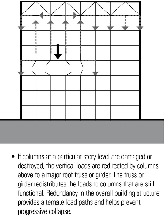
In addition to using factors of safety and employing ductile materials, another method for guarding against structural failure is to build redundancy into the structural design. A redundant structure includes members, connections, or supports not required for a statically determinate structure so that if one member, connection, or support fails, others exist to provide alternative paths for the transfer of forces. In other words, the concept of redundancy involves providing multiple load paths whereby forces can bypass a point of structural distress or a localized structural failure.
Redundancy, especially in the lateral-force-resisting systems of a structure, is highly desirable in earthquake-prone regions. It is also an essential attribute of long-span structures in which the failure of a primary truss, arch, or girder could lead to a large portion of the structure failing or even to its total collapse.

Extending structural redundancy to an entire structural system provides protection against progressive collapse of the structure. Progressive collapse can be described as the spread of an initial local failure from one structural member to another, eventually resulting in the collapse of an entire structure or a disproportionately large part of it. This is a major concern because progressive collapse can result in significant structural damage and loss of life.
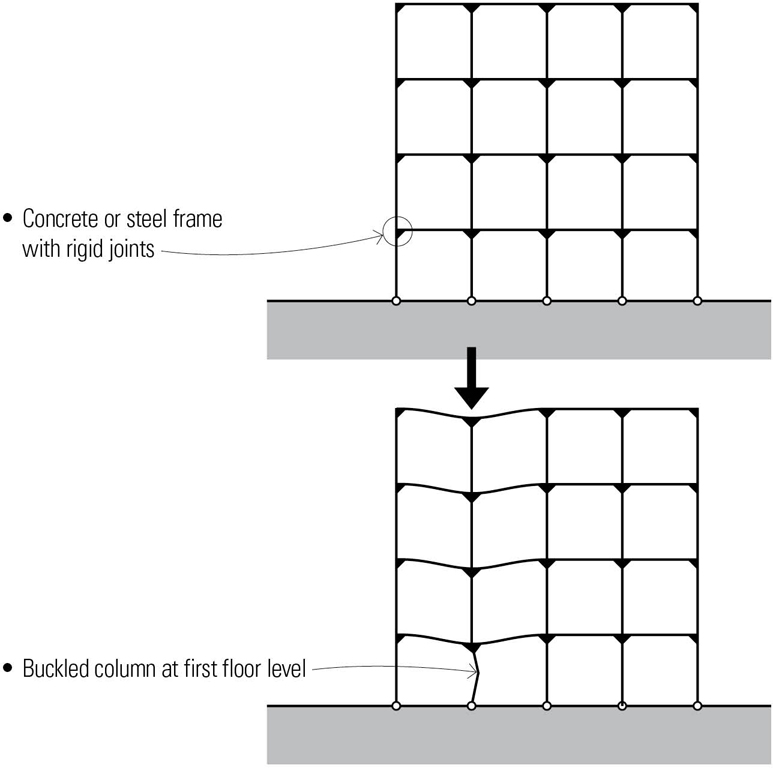
- A building frame connected with simple joints is subject to progressive collapse if one of its members or connections fails. With rigid beam-column connections, the same frame possesses ample load paths for both vertical and lateral loads.
- If a first-floor column were to fail, the rigid frame is able to redistribute the loads throughout the frame without collapsing.
Continuity
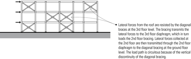
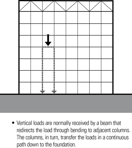
Continuity in a structure provides a direct, uninterrupted path for loads through a building’s structure, from the roof level down to the foundation. Continuous load paths help to ensure that all forces to which the structure is subjected can be delivered from the point of their application to the foundation. All elements and connections along a load path must have sufficient strength, stiffness, and deformation capability to transfer loads without compromising the building structure’s ability to perform as a unit.
- To prevent progressive collapse, structural members and assemblies should be adequately tied together so that forces and displacements can be transferred between vertical and horizontal elements of the structure.
- Strong connections increase the overall strength and stiffness of a structure by enabling all of the building elements to act together as a unit. Inadequate connections represent a weak link in a load path and are a common cause of the damage to and collapse of buildings during earthquakes.
- Rigid, non-structural elements should be isolated properly from the main structure to prevent attracting loads that can cause damage to the non-structural members and, in the process, create unintended load paths that can damage structural elements.
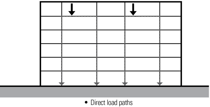
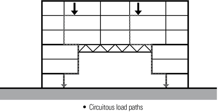
- Load paths through a building’s structure should be as direct as possible; offsets should be avoided.
- Disrupting the vertical alignment of columns and bearing walls on successive floors cause vertical loads to be diverted horizontally, inducing large bending stresses on the supporting beam, girder, or truss below and requiring deeper members.