8
Systems Integration
SYSTEMS INTEGRATION
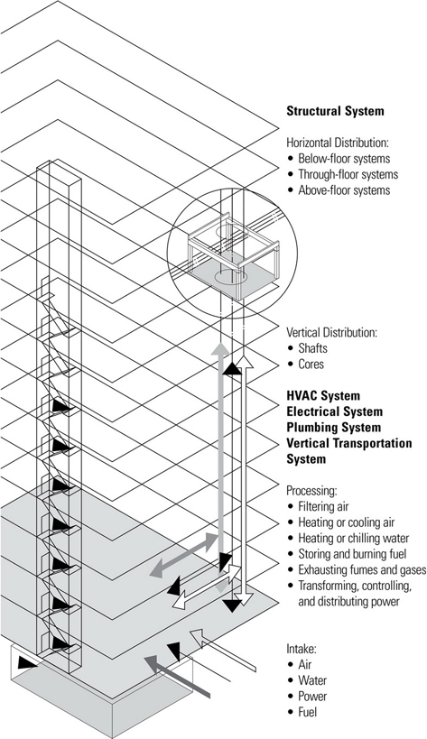
This chapter discusses the integration of the mechanical, electrical, and plumbing systems with the structural systems of buildings. These systems, which are integral to maintaining a comfortable, healthy, and safe building environment for the occupants, will typically include:
- Heating, ventilation, and air-conditioning (HVAC) systems that provide conditioned air to the interior spaces of a building. Conditioning may include ventilation, heating, cooling, humidification, and filtration.
- Electrical systems that provide power for lighting, electrical motors, appliances, and voice and data communications.
- Plumbing systems that provide a potable water supply, dispose of wastewater and sewage, control stormwater, and supply water to the fire suppression system.
The equipment and hardware of these systems require both considerable space and continuous distribution paths throughout a building. They are normally hidden from view within concealed construction spaces or special rooms but they require access for inspection and maintenance. Meeting these criteria requires careful coordination and integration in the planning and layout of the systems in relation to the structural system.
In addition to shafts and space for HVAC, electrical, and plumbing systems, the circulation system that provides access and emergency egress must also penetrate the structural system of multistory buildings. Providing shafts and space for corridors, stairways, elevators and escalators will not only influence the layout of the structural system but may, in some cases, become an integral part of the structure.
BUILDING SYSTEMS
Water Supply Systems
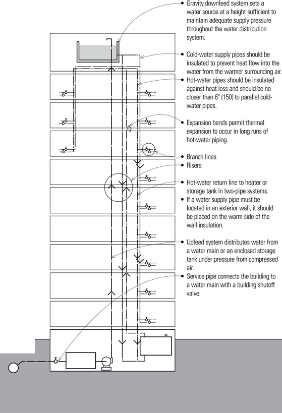
Water supply systems operate under pressure. The service pressure of a water supply system must be great enough to absorb pressure losses due to vertical travel and friction as the water flows through pipes and fittings, and still satisfy the pressure requirement of each plumbing fixture. Public water systems usually supply water at about 50 psi (345 kPa), which is sufficient for upfeed distribution in low-rise buildings up to six stories in height. For taller buildings, or where the water service pressure is insufficient to maintain adequate fixture service, water is pumped up to an elevated or rooftop storage tank for gravity downfeed. Part of this water is often used as a reserve for fire-protection systems.
The pressurized water supply side of the plumbing system results in smaller piping and more flexible distribution layouts. The water supply lines can usually be accommodated within floor and wall construction spaces without too much difficulty. It should be coordinated with the building structure and other systems, such as the parallel but bulkier sanitary drainage system. Water supply pipes should be supported at every story vertically and every 6 to 10 feet (1830 to 3050) horizontally. Adjustable hangers can be used to ensure proper pitch along horizontal runs for drainage.
- Water heaters are electric or gas appliances for heating water and storing it for use. Additional dispersed hot-water storage tanks may be required for large installations and widespread fixture groupings. Alternatively, in-line, on-demand water heaters that heat water at the time and point of use may be used. These systems alleviate the need for a storage tank but will require a flue if they burn fuel. Solar heating is also a possibility, either as a primary source of hot water in sunny climates or as a preheating system backed up by a standard water-heating system.

Fire Protection Systems
In large commercial and institutional buildings where public safety is an issue, building codes often require a fire sprinkler system to extinguish a fire before it can spread out of control; some codes allow an increase in floor area if an approved sprinkler system is installed. Some jurisdictions require the installation of fire sprinkler systems in multifamily housing as well.
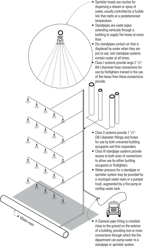
Fire sprinkler systems consist of pipes that are located in or below ceilings, connected to a suitable water supply, and supplied with valves or sprinkler heads made to open automatically at a certain temperature. Specific requirements for the use and location of the sprinkler heads make the planning and coordination of the system a priority in the design of ceilings and underfloor cavities.
The two major types of sprinkler systems are wet-pipe systems and dry-pipe systems.
- Wet-pipe systems contain water at sufficient pressure to provide an immediate, continuous discharge through sprinkler heads that open automatically in the event of a fire.
- Dry-pipe systems contain pressurized air that is released when a sprinkler head opens in the event of fire, allowing water to flow through the piping and out the opened nozzle. Dry-pipe systems are used where the piping is subject to freezing.
- Preaction systems are dry-pipe sprinkler systems through which water flow is controlled by a valve operated by fire-detection devices more sensitive than those in the sprinkler heads. Preaction systems are used when an accidental discharge would damage valuable materials.
- Deluge systems have sprinkler heads open at all times, through which water flow is controlled by a valve operated by a heat-, smoke-, or flame-sensing device.
Electrical Systems
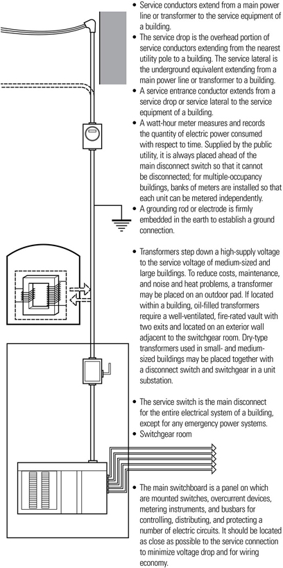
Utility companies transmit electrical power at high voltage to minimize voltage drop and conductor size in the transmission systems. For safety, transformers step this voltage down to lower voltages at the point of use. There are three different electrical system voltages commonly used in buildings:
- 120/240-volt, single-phase electrical power is typical for smaller-scale buildings and almost all residences. The utility owns and maintains transformers that provide 120/240-volt power from the high-voltage distribution line. The building requires only a meter, main disconnect, and distribution panel.
- 120/208-volt, three-phase electrical power is used in medium-sized buildings for the efficient operation of large motors used for fans, elevators, escalators; 120-volt power is provided as well for lighting and outlets. Such facilities would have a dry transformer to step down a high-supply voltage, located either outside of the building or inside as a unit substation.
- 277/480-volt, three-phase electrical power is used in large commercial buildings that will purchase their power at high voltage. These buildings require a large transformer along with a transformer vault. In addition there will be a separate switchboard room to partition the power to major users. Large motors in the building will use three-phase power while fluorescent lighting will use 277-volt, single-phase power. Electric closets will typically be required throughout the building, typically on each floor, to house smaller dry transformers to produce 120-volt, single-phase power for electrical outlets.
The electrical system of a building supplies power for lighting, heating, and the operation of electrical equipment and appliances. Generator sets may be required to supply emergency electrical power for exit lighting, alarm systems, elevators, telephone systems, fire pumps, and medical equipment in hospitals.
The service connection may be overhead or underground. Overhead service is less expensive, easily accessible for maintenance, and can carry high voltages over long runs. Underground service is more expensive but is used in high- load-density situations such as urban areas. The service cables are run in pipe conduit or raceways for protection and to allow for future replacement. Direct burial cable may be used for residential service connections.
Electrical Circuits
Once the electrical power requirements for the various areas of a building are determined, wiring circuits must be laid out to distribute the power to the points of use. Separate wiring circuits are required for the sound and signal equipment of telephone, cable, intercom, and security or fire alarm systems.
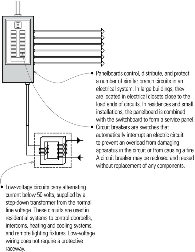
Electrical Wiring
Conduit provides support for wires and cables and protects them against physical damage and corrosion. Metal conduit also provides a continuous grounded enclosure for the wiring. For fireproof construction, rigid metal conduit, electrical metallic tubing, or flexible metal conduit can be used. For frame construction, armored or nonmetallic sheathed cable is used. Plastic tubing and conduits are most commonly used for underground wiring.
Being relatively small, conduit can be easily accommodated in most construction systems. Conduit should be adequately supported and laid out as directly as possible. Codes generally restrict the radius and number of bends a run of conduit may have between junction or outlet boxes. Coordination with a building’s mechanical and plumbing systems is required to avoid conflicting paths.
Heating, Ventilating, and Air-Conditioning Systems
Heating, ventilating, and air-conditioning (HVAC) systems simultaneously control the temperature, humidity, purity, distribution, and motion of the air in the interior spaces of a building.
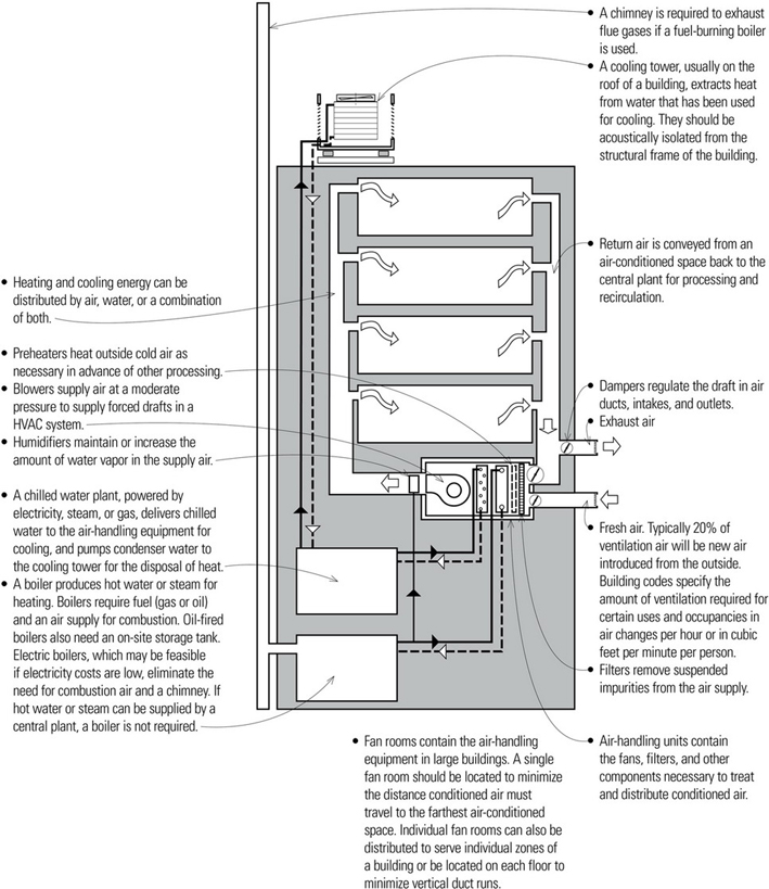
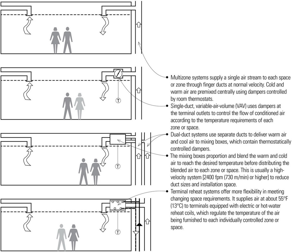
All-Air HVAC Systems
The air treatment and refrigeration source in all-air systems may be located in a central location some distance from the conditioned spaces. Only the final heating-cooling medium (air) is brought into the conditioned space through ducts and distributed within the space through outlets or mixing terminal-outlets. All-air systems can not only provide heat and cooling but also clean the air and control humidity. Air is returned to the central unit and mixed with outside air for ventilation.
All-Water HVAC Systems
All-water systems supply hot or chilled water from a central location to fan-coil units located in the conditioned spaces through pipes, which require less installation space than air ducts.
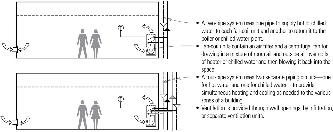
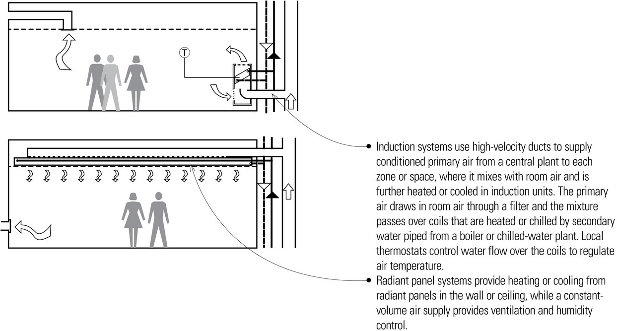
Air-Water HVAC Systems
In air-water systems, the air treatment and refrigeration source may be separated from the served spaces. However, the temperature of the air delivered to the conditioned spaces is primarily balanced by warm or cool water circulated in an induction unit or radiant panel in the conditioned spaces. Air may be returned to the central unit or exhausted directly. Common types of air-water systems include:
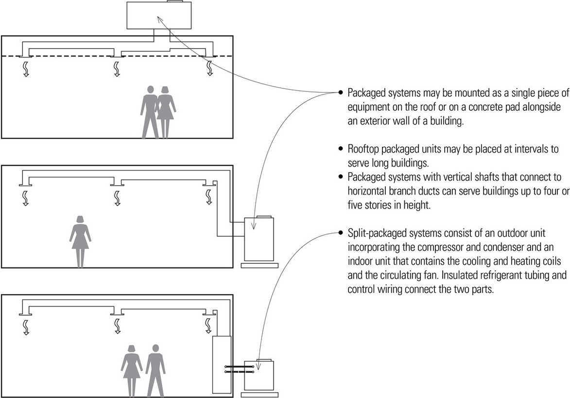
Packaged HVAC Systems
Packaged systems are self-contained, weatherproof units incorporating a fan, filters, compressor, condenser, and evaporator coils for cooling. For heating, the unit may operate as a heat pump or contain auxiliary heating elements. Packaged systems are powered by electricity or by a combination of electricity and gas.
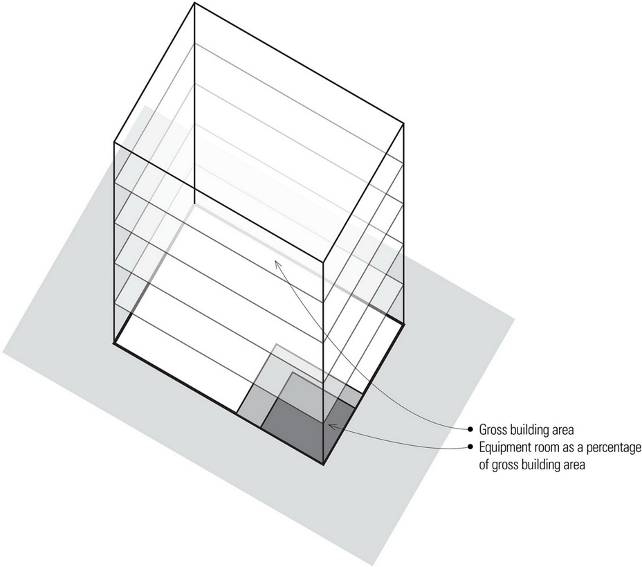
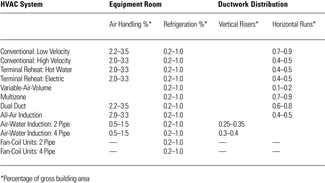
Typical Space Requirements for HVAC Systems
For schematic design purposes, the space required for the various types of HVAC systems can be estimated as a percentage of gross floor area. In the table below, the gross area of the entire building can be used to estimate the size of equipment rooms as well as the gross area served for the duct space. Where not otherwise indicated, space for the vertical risers is included in the equipment room percentage.
VERTICAL DISTRIBUTION
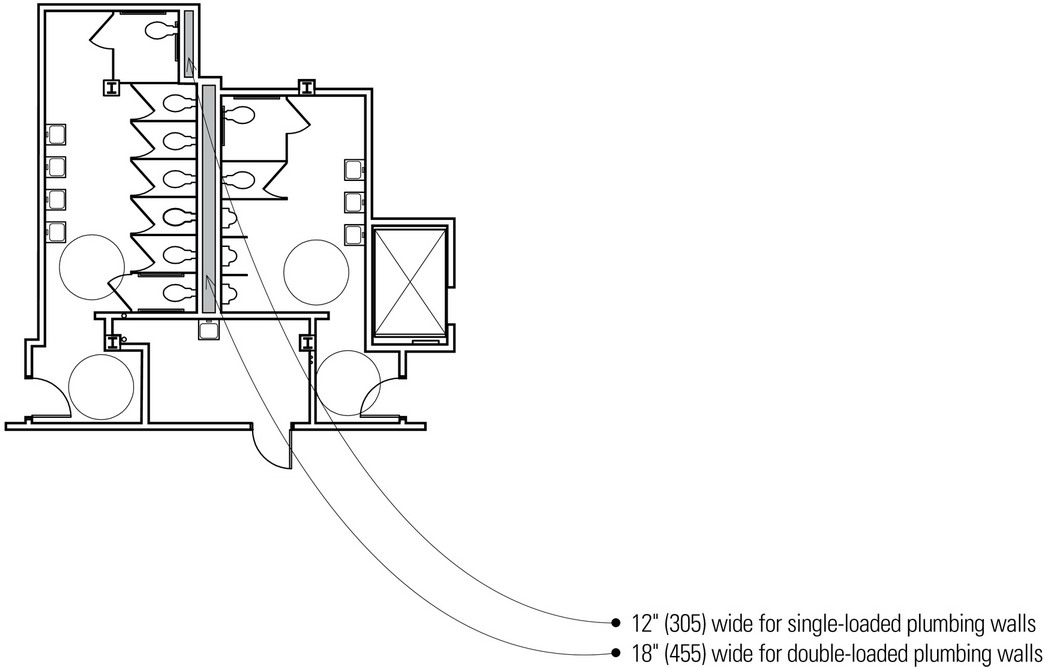
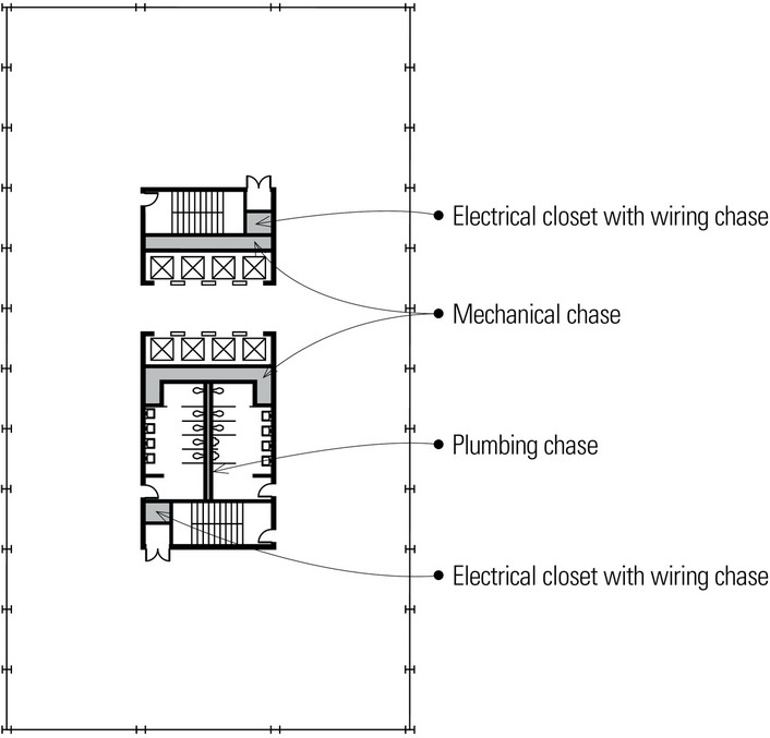
Plumbing Chases
Plumbing chases provide the space necessary for the water supply and sanitary sewage lines in a building. They are almost invariably associated with lavatories, kitchens, and laboratories. Potential conflicts between a building structure and plumbing lines can be avoided by restricting supply and drainage piping to vertical plumbing chases.
- For reasons of economy and access, it is desirable to arrange the plumbing waste and vent stacks in a vertical chase extending through all of the floors of multistory buildings.
- Locating rooms that require plumbing above one another with the fixtures backed up to a common plumbing wall or chase creates room for the waste and vent stacks and for the plumbing runs that often must cross the stacks horizontally.
- Plumbing chases provide easier access for maintenance.
- Plumbing or wet walls behind fixtures should be deep enough to accommodate branch lines, fixture runouts, and air chambers.
- Horizontal sanitary sewage and stormwater lines must be sloped to drain and thus have priority in the planning of the horizontal mechanical space.
Although the use of plumbing chases is less critical in low-rise buildings, it is a particularly efficient approach to organizing and laying out the plumbing systems of certain building types, such as high-rise structures, hotels, hospitals, and dormitories.
Fan Rooms
While it is more efficient to locate a fan room in a central location to reduce the length of air supply ducts, it may be located anywhere in a building that provides an outside air source and exhaust, and from which vertical shafts can accommodate the necessary supply and return air ducts.
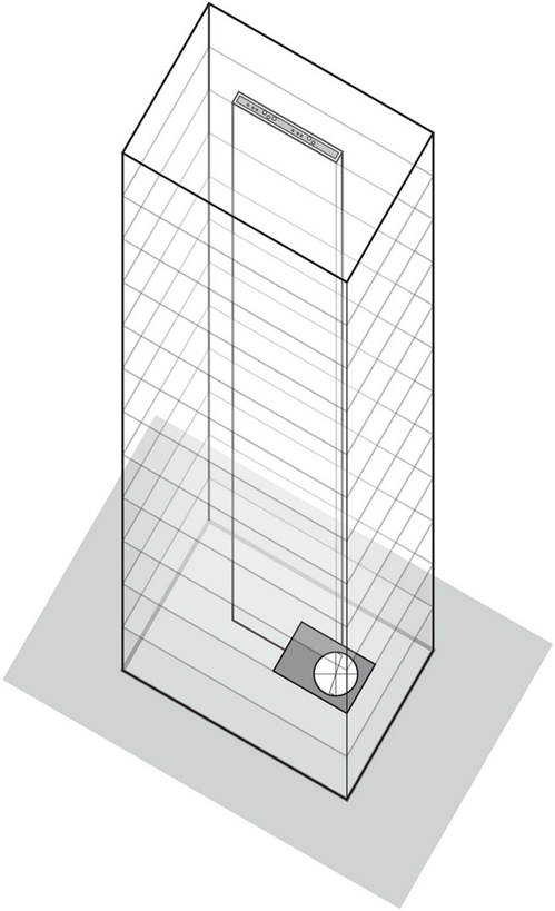
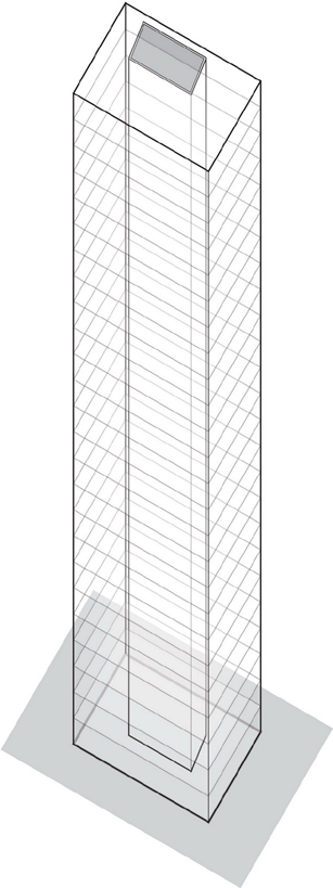
- In large buildings, it may be economical to use multiple fan rooms for different zones of service.
- Air handlers are limited in forcing air up or down through a maximum of 10 to 15 floors. In taller buildings, multiple fan rooms are required, resulting in mechanical floors spaced 20 to 30 floors apart. Some tall buildings eliminate the need for vertical shafts by locating a fan room on each floor.
Cores
In buildings two to three stories high, vertical chases for mechanical services are often located wherever they can be accommodated within the floor plans and provide service where it is needed. Without careful planning, this can result in weaving ductwork, piping, and wiring in and around the building structure, making access for maintenance or alterations difficult and reducing the efficiency of the systems.
In large and tall buildings, mechanical chases are often located with other shafts, such as those enclosing exit stairways, elevators, and plumbing risers. This naturally leads to the grouping of these facilities into one or more efficient cores that extend vertically through the height of the building. Because these cores are continuous as they rise through multiple floors—and additional fire protection is required in their construction—they can also serve as shear walls to help resist lateral loads as well as bearing walls to assist in carrying gravity loads.
Core Locations
The service core or cores of a building house the vertical distribution of mechanical and electrical services, elevator shafts, and exit stairways. These cores must be coordinated with the structural layout of columns, bearing walls, and shear walls or lateral bracing as well as with the desired patterns of space, use, and activity.
The building type and configuration will influence the location of vertical cores.
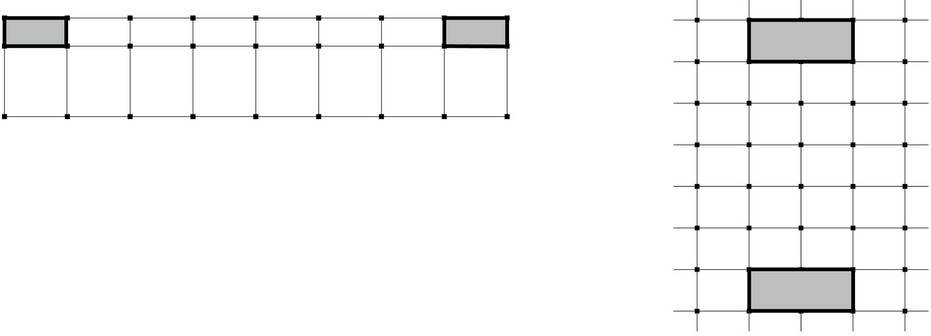
- A single core is often used in high-rise office buildings to leave a maximum amount of unobstructed rentable area.
- Central locations are ideal for short horizontal runs and efficient distribution patterns.
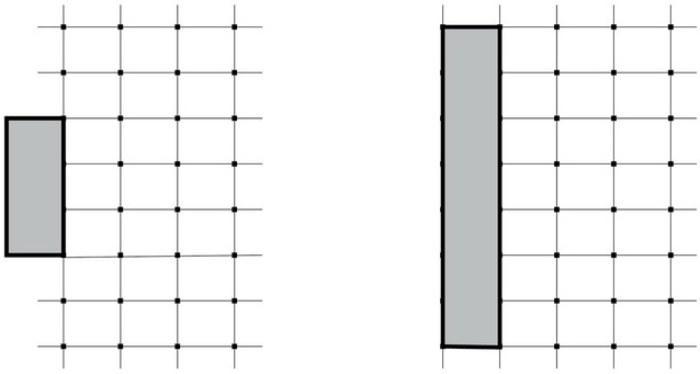
- Placing the core along an edge leaves an unobstructed floor space but occupies a portion of the daylit perimeter.
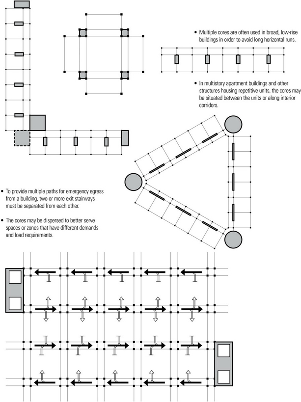
- Detached cores leave a maximum amount of floor space but require long service runs and cannot contribute lateral bracing to the building.
- Two cores may be symmetrically placed to reduce service runs and to serve effectively as lateral bracing, but the remaining floor area loses some flexibility in layout and use.
HORIZONTAL DISTRIBUTION
Horizontal Distribution of Mechanical Services
Mechanical services are distributed to and from vertical shafts and chases in a horizontal manner through the floor-ceiling assemblies of a building. The manner in which these services relate to the depth of the structural spanning system determines the vertical extent of the floor-ceiling assemblies, which in turn has a significant effect on the overall height of a building.
There are three fundamental ways in which to distribute the horizontal runs of mechanical services:
- Above the spanning structure
- Through the spanning structure
- Below the spanning structure
Wiring and supply pipes require little space and can readily be run in small chases and floor or ceiling cavities. Distributing air, however, requires supply and return ducts of significant size. This is particularly true of systems where reduced noise is important and air is supplied at a low velocity, or where a small differential between a desired temperature and that of the supplied air requires a high volume of air movement. HVAC systems, therefore, pose the greatest potential conflict with both the horizontal and vertical dimensions of a building structure.
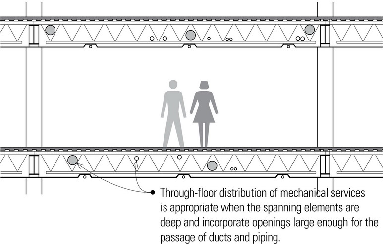
Horizontal Distribution of Mechanical Services Through the Floor Structure
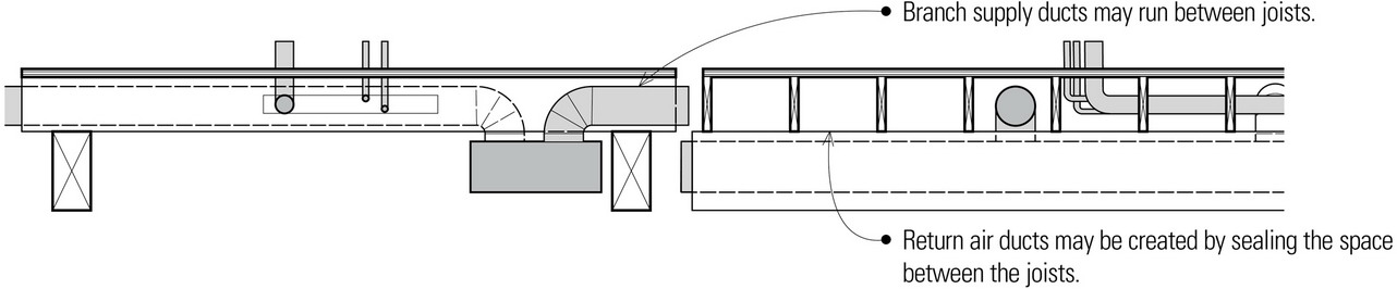
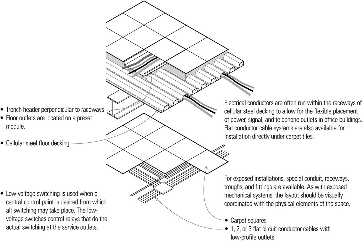
The horizontal distribution of mechanical services through a spanning structure is made possible by the openings inherent in certain structural elements, such as steel and wood trusses, light-gauge steel joists, hollow-core concrete planks, cellular steel decking, and wood I-joists.
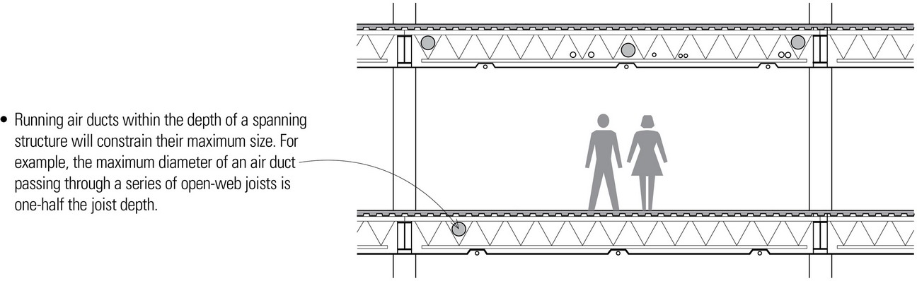
- Running air ducts through floor trusses or in the space between joists reduces the flexibility of the mechanical system to accommodate change.
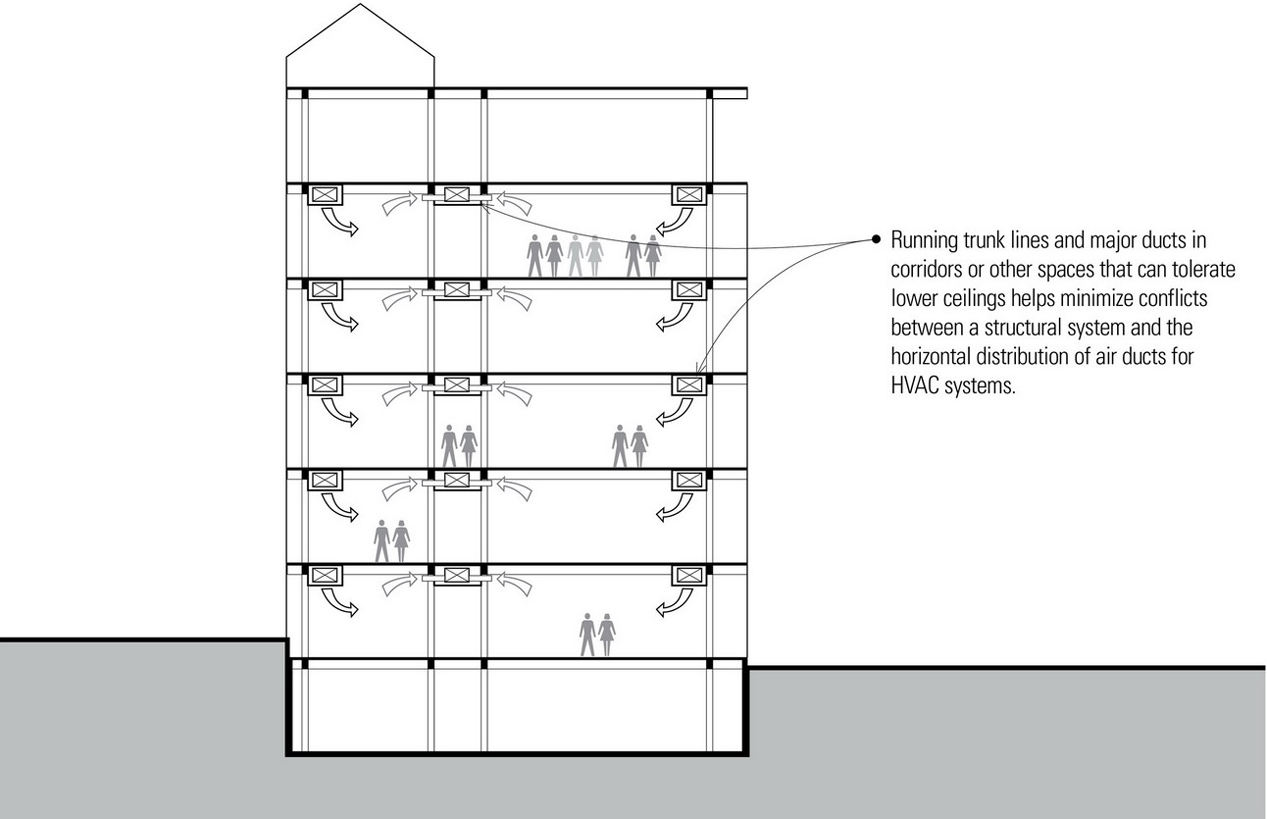
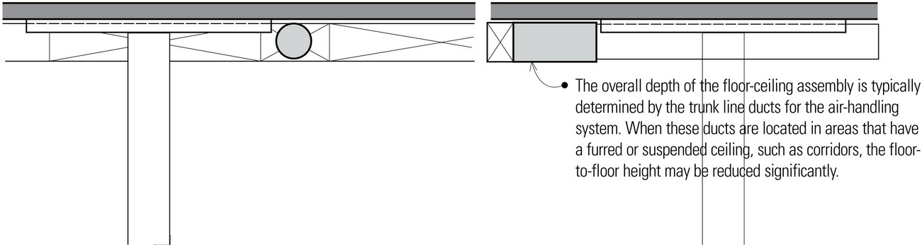
- Large ducts such as trunk lines may require dropped ceilings and are often run in corridors or other spaces where the ceiling height can be reduced.
- Note that it is sometimes difficult to run rigid elements of mechanical systems through openings in structural members within the sequence of construction.
Specialized building systems have been developed to accommodate integrating some mechanical systems with the structural system.
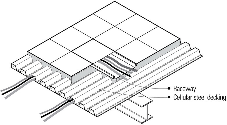
- Raceways for wiring may be cast into structural or topping slabs. The raceways can, in some cases, reduce the effective slab thickness.
- Some steel decking allows the underside of the corrugations to be used as a raceway for electrical wiring.
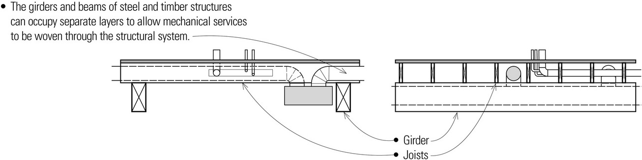
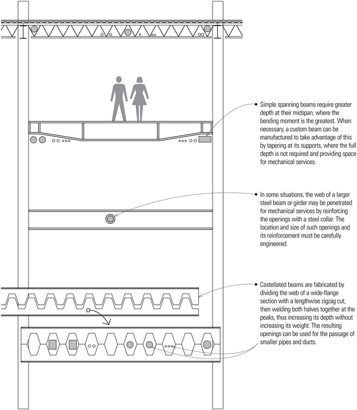
Beams can be shaped or penetrated to permit the passage of mechanical services.
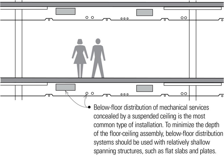
Horizontal Distribution of Mechanical Services Below the Structural Floor
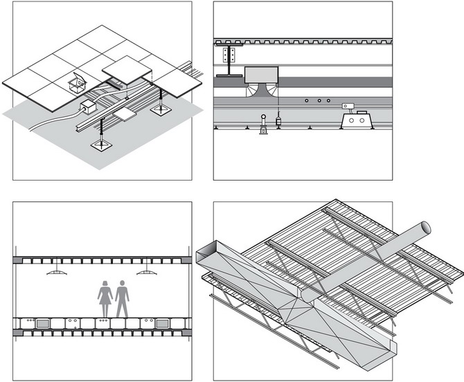
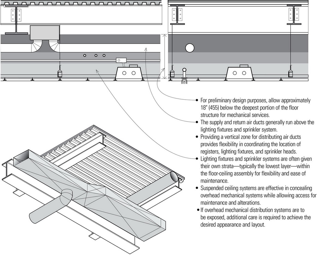
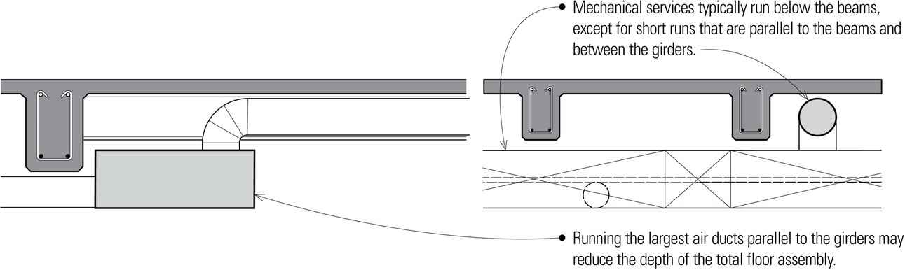
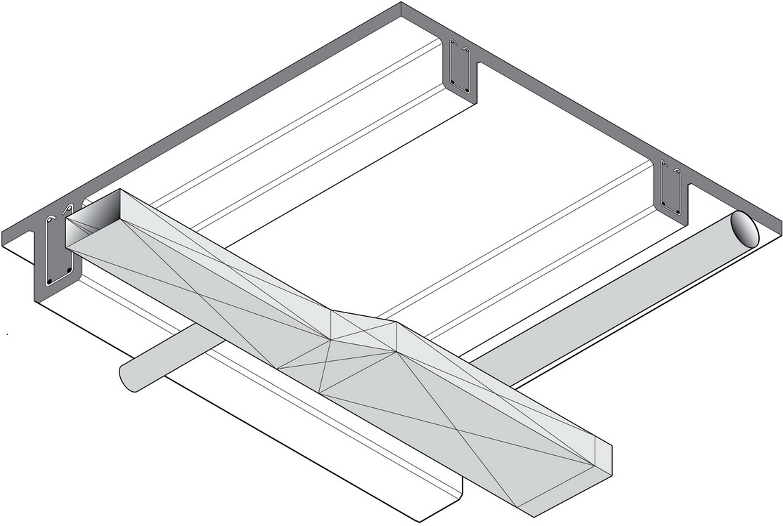
When the mechanical systems are located below the floor structure, the horizontal zone layer immediately below the structure is reserved for the distribution of air ducts. For maximum efficiency, the main or trunk lines of air ducts should run parallel to the girders or main beams. Where necessary, the smaller branch ducts cross under the girders to minimize the total floor depth. The lowest layer is typically reserved for lighting fixtures and the sprinkler system that extend through the ceiling.
- Suspended ceiling systems, electrical components, ductwork, and access floors must be braced to resist displacement under lateral loading as well as against the upward forces during a seismic event that can dislodge systems not braced for reversal of gravity loads.
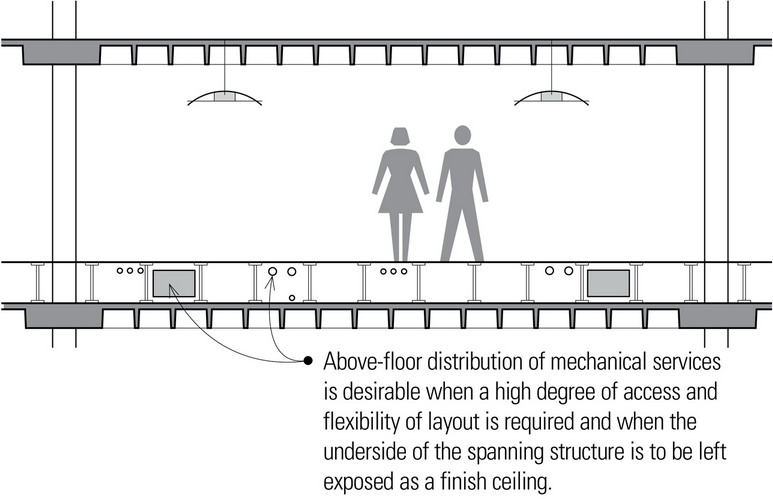
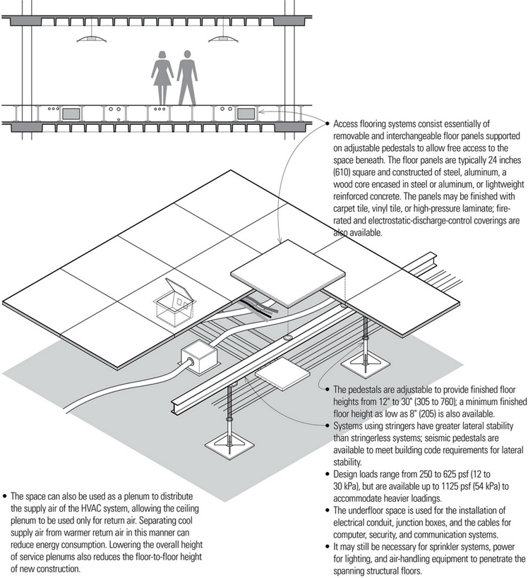
Horizontal Distribution of Mechanical Services Above the Structural Floor
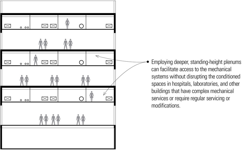
Access flooring systems are typically used in office spaces, hospitals, laboratories, computer rooms, and television and communication centers to provide accessibility and flexibility in the placement of desks, workstations, and equipment. Equipment can be moved and reconnected fairly easily with modular wiring systems. They are also a desirable option when the underside of the spanning structure, such as a waffle slab, is to be exposed as a finish ceiling.
INTEGRATION STRATEGIES
Flat Plates and Slabs
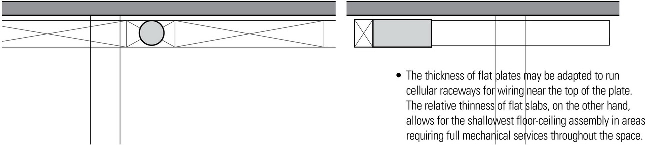
- Due to the unobstructed space below flat plates and between the drop panels of flat slabs, mechanical services may run in both directions in all areas, providing the greatest flexibility and adaptability in laying out mechanical services.
One-Way Slab and Beams
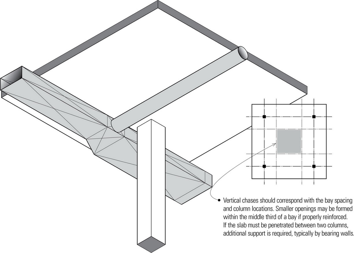
- Relatively small openings are usually not detrimental to the structural behavior of beam-supported slabs. As a general rule, the equivalent of the interrupted reinforcement should be added at the sides of the opening, and additional diagonal bars should be included at the corners for crack control.
- If the slab must be penetrated between two columns, additional support is required, typically by bearing walls.
- Flexibility of beam and slab layout allows for the integration of spatial and structural planning modules.
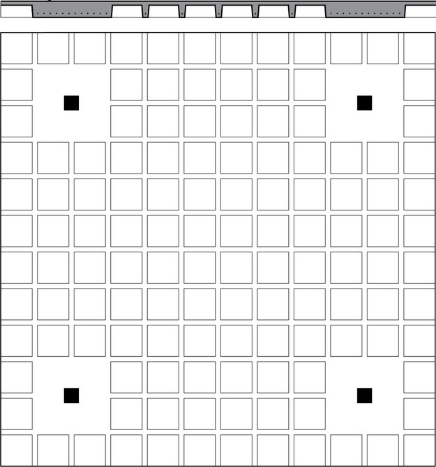
Joist and Waffle Slabs
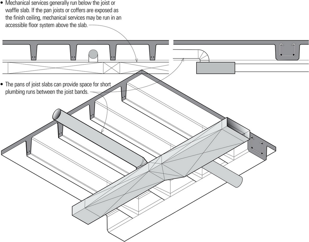
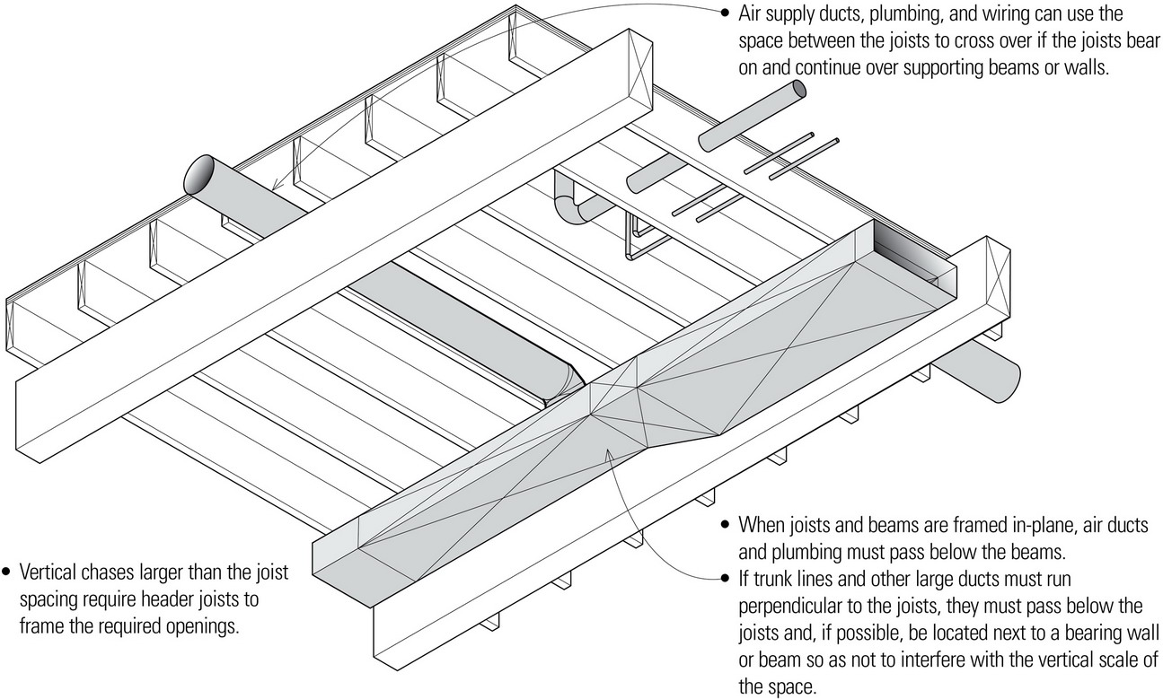
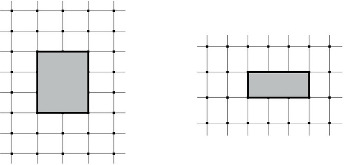
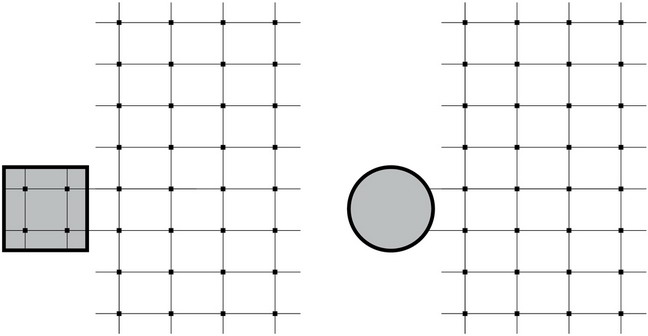
- Large vertical chases and openings should be accommodated and framed within the column grid. Smaller openings should be coordinated with the joist or rib spacing.
- Small holes can be cut in the slab between the joists or ribs. However, mechanical services should not penetrate the joists, ribs, or solid bands of joist and waffle slabs.
- The location of ceiling fixtures, such as luminaires and fire sprinklers, require careful integration with the coffers of waffle slabs.
Precast Concrete Planks
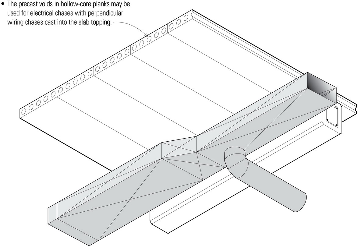
- If the concrete planks are exposed as the finish ceiling, additional care is required in locating and installing the exposed air ducts for the desired appearance. The exposed planks may also dictate the use of surface wiring with exposed conduit and exposing horizontal plumbing runs that may not be desirable.
- Vertical chases should be coordinated with the beam spacing. Openings the width of a single plank can be created by hanging the cut plank off of adjacent planks; wider openings must be supported on additional beams or bearing walls.
Structural Steel Framing
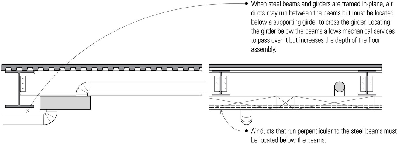
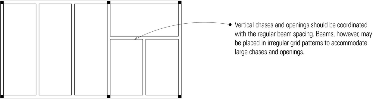
- Vertical chases and openings should be coordinated with the beam spacing. If larger than the beam spacing, they require additional framing.
- When necessary, structural steel beams can be modified and reinforced to accommodate mechanical services within their webs. Custom-fabricated steel beams can also be tapered, haunched, or castellated to provide space for mechanical services. See figure in ‘Horizontal Distribution of Mechanical Services through the Floor Structure’.
Post-and-Beam Construction
- Vertical chases larger than the beam spacing require header beams. Ideally, beam spacing should be coordinated with the dimensions of any vertical chases.
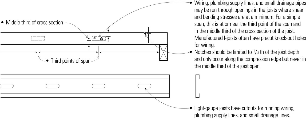
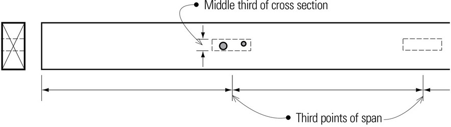
- Because beams behave as independent structural members, unlike repetitive joist members, it is less desirable to run wiring and plumbing supply and drainage lines through beams. If wood beams must be drilled to accommodate wiring or supply plumbing, the holes should be located where shear and bending stresses are at a minimum. For a simple span, this is at or near the middle third of the span and in the middle third of the cross section of the beam.
- If the wood decking supported by timber beams is exposed as the finish ceiling, additional care is required in locating and installing any exposed air ducts for the desired appearance. Exposed decking may also dictate the use of surface wiring with potentially undesirable exposed conduit and horizontal plumbing runs.
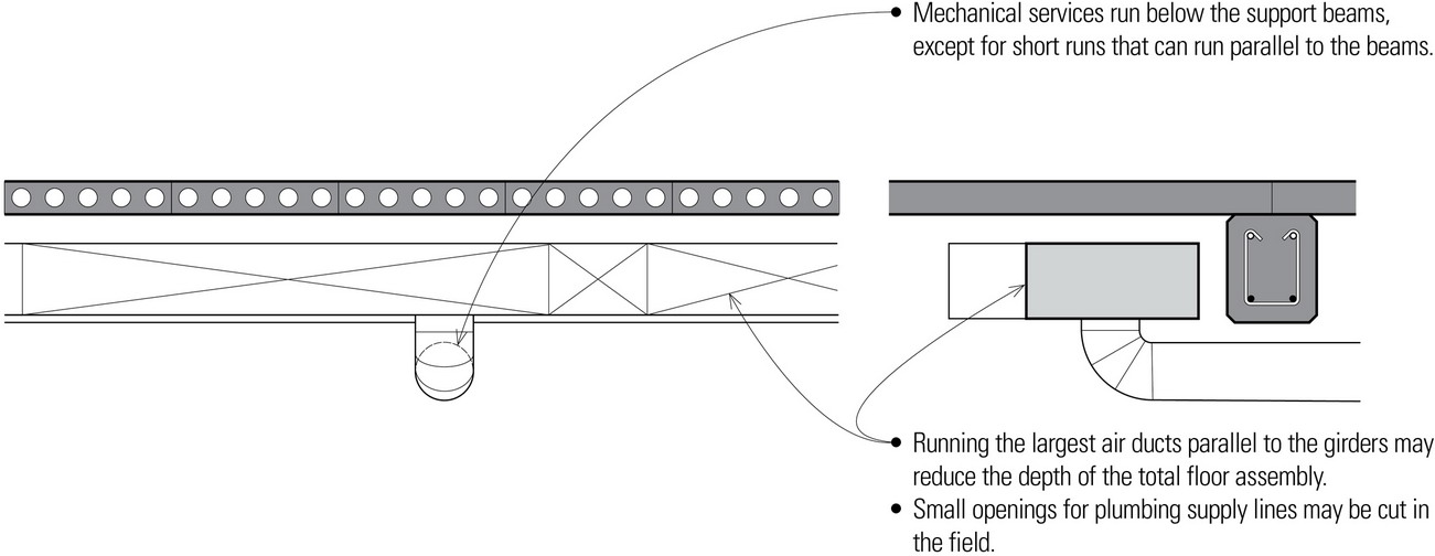
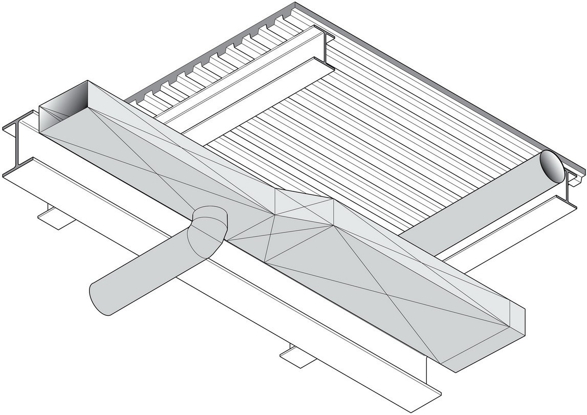
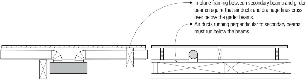
Open-Web Steel Joists
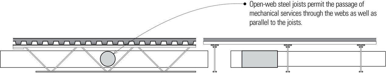
- When open-web joists are supported on steel beams, air ducts and plumbing lines must pass below the beams, or the beams must be modified to accommodate penetrations through their webs.
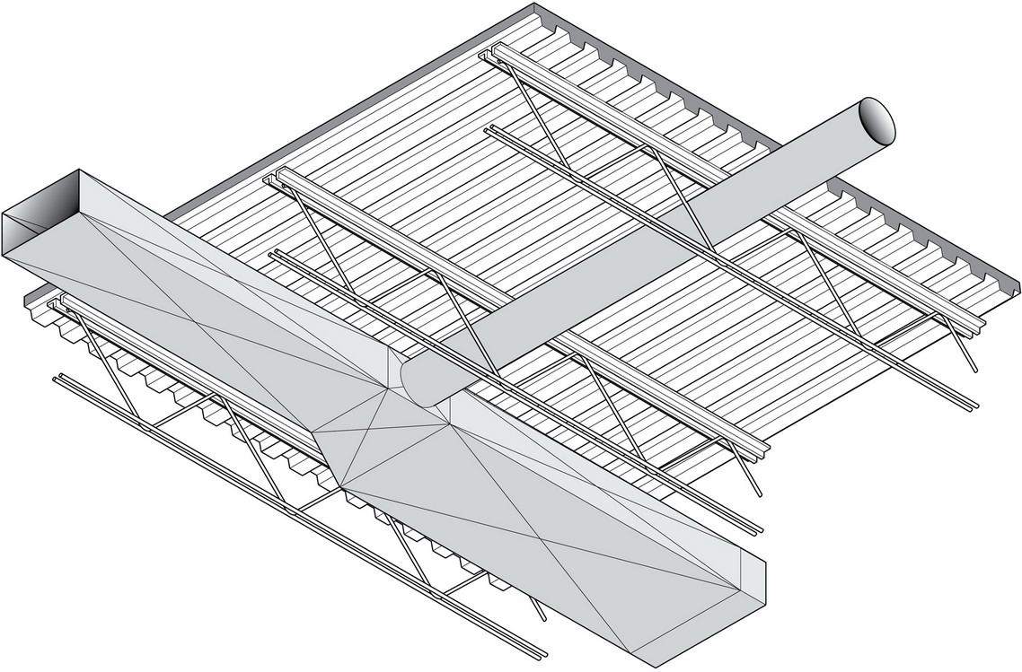
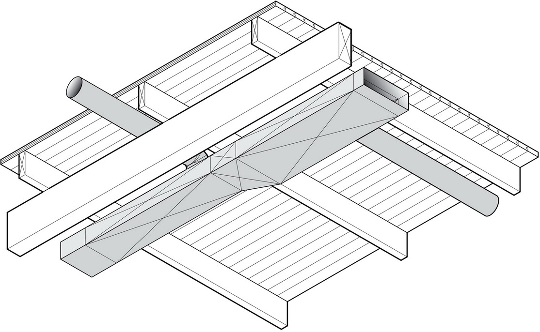
- Supporting open-web joists on girder trusses may allow mechanical services to pass through the girders when running parallel to the open-web joists. Note that a girder truss is typically deeper than a steel beam carrying an equivalent load, creating a deeper floor construction.
- Small vertical openings may be framed with steel angle headers supported by trimmer joists. Large openings, however, require structural steel framing.
Light Frame Construction