Chapter 6
Communication and Network Security
IN THIS CHAPTER
 Assessing and implementing secure design principles in network architectures
Securing network components
Implementing secure communication channels according to design
The Communication and Network Security domain requires a thorough understanding of network fundamentals, secure network design, concepts of network operation, networking technologies, and network management techniques. This domain represents 14 percent of the CISSP certification exam.
 A thorough understanding of networking protocols, services, practices, and architecture will definitely help you pass the exam. If your network experience is light, we recommend that you pick up a copy of Networking All-In-One For Dummies (John Wiley & Sons, Inc.). Also consider earning a networking certification, such as CompTIA Network+ or Cisco Certified Network Associate (CCNA), before taking the CISSP exam. These materials are extremely helpful in preparing for this portion of the CISSP exam if your background is light in network technology.
Assess and Implement Secure Design Principles in Network Architectures
A solid understanding of networking concepts and fundamentals is essential for creating a secure network architecture. This understanding requires knowledge of network topologies; IP addressing; various networking protocols (including multilayer and converged protocols); wireless networks; communication security; and new and evolving networking trends, such as software-defined networks, microsegmentation, and cloud computing.
 This section covers Objective 4.1 of the Communication and Network Security domain in the CISSP Exam Outline (May 1, 2021).
Data networks are commonly classified as local area networks and wide area networks. Although these classifications are basic, you should understand the fundamental distinctions between these two types of networks.
A local area network (LAN) is a data network that operates across a relatively small geographic area, such as a single building or floor. A LAN connects workstations, servers, printers, and other devices so that network resources, such as files and email, can be shared. Key characteristics of LANs include the following:
- Can connect networked resources over a small geographic area, such as a floor, a building, or a group of buildings.
- Are relatively inexpensive to set up and maintain, typically consisting of readily available equipment such as servers, desktop PCs, printers, switches, hubs, bridges, repeaters, wireless access points, and various security devices such as firewalls and intrusion prevention systems.
- Can be wired, wireless, or a combination of wired and wireless.
- Perform at relatively high speeds — typically 10 megabits per second (Mbps), 100 Mbps, 1000 Mbps (also referred to as 1 gigabit per second [1 Gbps]), 10 Gbps, and 40 Gbps for wired networks, and 11 Mbps, 54 Mbps, or 600 Mbps for wireless networks. We cover LAN speeds in the section “Physical Layer (Layer 1)” later in this chapter.
 Be careful when referring to data capacity (and their abbreviations) and data storage. 100 Mbps is100 megabits per second, and 100 MB is 100 megabytes. The distinction is subtle (a little b versus a big B and bits rather than bytes), but the difference is significant: A byte is equal to 8 bits. Data speeds are typically referred to in bits per second; data storage is typically referred to in bytes.
 A LAN is a data network that operates across a relatively small geographic area, such as a building or group of buildings.
A wide area network (WAN) connects multiple LANs and other WANs by using telecommunications devices and facilities to form an internetwork. Key characteristics of WANs include the following:
- Connects multiple LANs over large geographic areas, such as a small city (such as a metropolitan area network), a region or country, a global corporate network, the entire planet (such as the Internet), or beyond (such as the International Space Station via satellite).
- Can be relatively expensive to set up and maintain, typically consisting of equipment such as routers, channel service unit/data service unit devices, firewalls, virtual private networks (VPNs), gateways, and various other security devices.
- Perform at relatively low speeds by using various technologies, such as digital subscriber line (DSL; 128 Kbps to 16 Mbps, for example), T-1 (1.544 Mbps), DS-3 (approximately 45 Mbps), OC-12 (approximately 622 Mbps), and OC-255 (approximately 13 Gbps). We cover WAN speeds in the section “Data Link Layer (Layer 2)” later in this chapter.
AWAN is a data network that operates across a relatively large geographic area and includes portions supplied by telecommunications carriers.
OSI and TCP/IP models
The OSI and TCP/IP models define standard protocols for network communication and interoperability by using a layered approach. This approach divides complex networking issues into simpler functional components that aid in the understanding, design, and development of networking solutions. It provides the following specific advantages:
- Clarifies the general functions of a communications process instead of focusing on specific issues
- Reduces complex networking processes into simpler sublayers and components
- Promotes interoperability by defining standard interfaces
- Aids development by allowing vendors to change individual features at a single layer instead of rebuilding the entire protocol stack
- Facilitates easier (and more logical) troubleshooting
The OSI model isn’t just a theoretical model to be pondered by intellectuals; it really is helpful for explaining complex networking topics. For this reason, much of the information you need to know for the Communication and Network Security domain is presented in this chapter in the context of the OSI model. You don’t necessarily need to know which protocols and equipment belong to which layers of the OSI model for the CISSP exam or in your day-to-day work. We’ve presented it this way to logically organize the information you need to know for this domain.
The OSI Reference Model
In 1984, the International Organization for Standardization (ISO) adopted the Open Systems Interconnection (OSI) Reference Model (or simply the OSI model) to facilitate interoperability between network devices independent of the manufacturer.
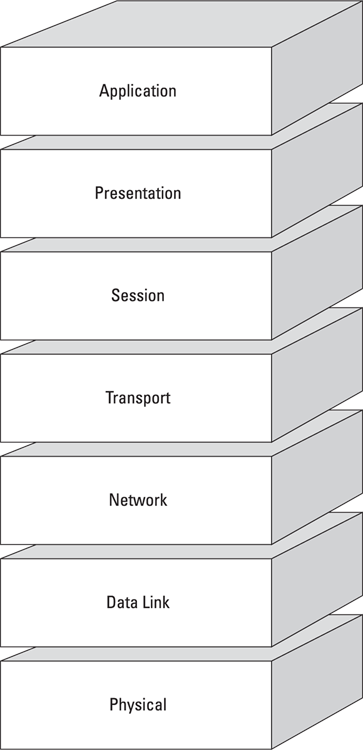
The OSI model consists of seven distinct layers that describe how data is communicated between systems and applications on a computer network, as shown in Figure 6-1. These layers include
© John Wiley & Sons, Inc.
FIGURE 6-1: The seven layers of the OSI model.
- Application (Layer 7)
- Presentation (Layer 6)
- Session (Layer 5)
- Transport (Layer 4)
- Network (Layer 3)
- Data Link (Layer 2)
- Physical (Layer 1)
Try creating a mnemonic to recall the layers of the OSI model, such as All People Seem To Need Delicious Pizza and, in reverse, Please Do Not Throw Sausage Pizza Away. (Now we’re getting hungry.)
In the OSI model, data is passed from the highest layer (Application, Layer 7) downward through each layer to the lowest layer (Physical, Layer 1) and then transmitted across the network medium to the destination node, where it’s passed upward from the lowest layer to the highest layer. Each layer communicates only with the layer immediately above and below it (adjacent layers). This communication is achieved through a process known as data encapsulation, which wraps protocol information from the layer immediately above in the data section of the layer immediately below. Figure 6-2 illustrates this process.

© John Wiley & Sons, Inc.
FIGURE 6-2: Data encapsulation in the OSI model.
Application Layer (Layer 7)
The Application Layer (Layer 7) is the highest layer of the OSI model. It supports the components that deal with the communication aspects of an application that requires network access, and it provides an interface to the user. So both the Application Layer and the end user interact directly with the application.
The Application Layer is responsible for the following:
- Identifying and establishing availability of communication partners
- Determining resource availability
- Synchronizing communication
The Application Layer is responsible for identifying and establishing availability of communication partners, determining resource availability, and synchronizing communication.
Don’t confuse the Application Layer with software applications such as Microsoft Word and Excel. Applications that function at the Application Layer include
- File Transfer Protocol (FTP) and Secure File Transfer Protocol (SFTP): A program used to copy files from one system to another over a network. FTP operates on TCP ports 20 (the data port) and 21 (the control port), while SFTP only requires TCP port 22 by default.
- Hypertext Transfer Protocol (HTTP): The language of the World Wide Web, used by web servers and browsers for non-sensitive content. HTTP operates on TCP port 80.
- Hypertext Transfer Protocol Secure (HTTPS): The language of commercial transactions on the World Wide Web. HTTPS is actually the HTTP protocol used in combination with SSL/TLS (discussed in the section “Transport Layer (Layer 4)”). HTTPS operates on TCP port 443 but occasionally on other ports such as 8443.
- Internet Message Access Protocol (IMAP): A store-and-forward electronic mail protocol that allows an email client to access, manage, and synchronize email on a remote mail server. IMAP provides more functionality and security than POP3, such as requiring users to explicitly delete emails from the server. The most current version is IMAPv4 (or IMAP4), which operates on TCP and UDP port 143. Email clients that use IMAP can be secured by using TLS or SSL encryption over TCP/UDP port 993.
- Post Office Protocol Version 3 (POP3): An email retrieval protocol that allows an email client to access email on a remote mail server by using TCP port 110. Inherently insecure, POP3 allows users to authenticate over the Internet by using plaintext passwords. Email clients that use POP3 can be secured by using TLS or SSL encryption over TCP/UDP port 995.
- Privacy Enhanced Mail (PEM): PEM is an Internet Engineering Task Force standard (IETF) for providing email confidentiality and authentication. PEM is not widely used.
- Secure Multipurpose Internet Mail Extensions (S/MIME): S/MIME is a secure method of sending email incorporated into several popular browsers and email applications.
- Simple Mail Transfer Protocol (SMTP): Used to send and receive email across the Internet. This protocol has several well-known vulnerabilities that make it inherently insecure. SMTP operates on TCP/UDP port 25. SMTP over SSL/TLS (SMTPS) uses TCP/UDP port 465.
- Simple Network Management Protocol (SNMP): Used to collect network information by polling stations and sending traps (alerts) to a management station. SNMP has many well-known vulnerabilities, including default cleartext community strings (passwords). SNMP operates on TCP/UDP ports 161 (agent) and 162 (manager). Secure SNMP uses TCP/UDP ports 10161 (agent) and 10162 (manager).
- Telnet: Provides terminal emulation for remote access to system resources. Telnet operates on TCP/UDP port 23. Because Telnet transmits passwords in cleartext, it is no longer considered safe; SSH (discussed in the section “Session Layer (Layer 5)” later in this chapter) is preferred.
- Trivial File Transfer Protocol (TFTP): A lean, mean version of FTP without directory-browsing capabilities or user authentication. Generally considered to be less secure than FTP, TFTP operates on UDP port 69.
Presentation Layer (Layer 6)
The Presentation Layer (Layer 6) provides coding and conversion functions that are applied to data being presented to the Application Layer (Layer 7). These functions ensure that data sent from the Application Layer of one system are compatible with the Application Layer of the receiving system.
The Presentation Layer is responsible for coding and conversion functions.
Tasks associated with this layer include
- Data representation: Use of common data representation formats (standard image, sound, and video formats) enables application data to be exchanged between different types of computer systems.
- Character conversion: Information is exchanged between different systems by using common character conversion schemes.
- Data compression: Common data compression schemes enable compressed data to be decompressed properly at the destination.
- Data encryption: Common data encryption schemes enable encrypted data to be decrypted properly at the destination.
Examples of Presentation Layer protocols include
- American Standard Code for Information Interchange (ASCII): A character-encoding scheme based on the English alphabet, consisting of 128 characters.
- Extended Binary-Coded Decimal Interchange Code (EBCDIC): An 8-bit character-encoding scheme largely used on mainframe and mid-range computers.
- Graphics Interchange Format (GIF): A widely used bitmap image format that allows up to 256 colors and is suitable for images or logos (but not photographs).
- Joint Photographic Experts Group (JPEG): A photographic compression method widely used to store and transmit photographs.
- Motion Picture Experts Group (MPEG): An audio and video compression method widely used to store and transmit audio and video files.
Session Layer (Layer 5)
The Session Layer (Layer 5) establishes, coordinates, and terminates communication sessions (service requests and service responses) between networked systems.
The Session Layer is responsible for establishing, coordinating, and terminating communication sessions between systems.
A communication session is divided into three distinct phases:
- Connection establishment: Initial contact between communicating systems is made, and the end devices agree on communications parameters and protocols to be used, including the mode of operation:
- Simplex mode: In simplex mode, a one-way communications path is established with a transmitter at one end of the connection and a receiver at the other end. An analogy is AM radio; a radio station broadcasts music, and the radio receiver can only receive the broadcast.
- Half-duplex mode: In half-duplex mode, both communicating devices are capable of transmitting and receiving messages, but they can’t do so at the same time. An analogy is a two-way radio; a button must be pressed to transmit and then released to receive a signal.
- Full-duplex mode: In full-duplex mode, both communicating devices are capable of transmitting and receiving simultaneously. An analogy is a telephone; it can transmit and receive signals (but not necessarily communicate) at the same time.
- Data transfer: Information is exchanged between end devices.
- Connection release: When data transfer is complete, end devices systematically end the session.
Examples of Session Layer protocols include
- Network Basic Input/Output System (NetBIOS): A Microsoft protocol that allows applications to communicate over a LAN. When NetBIOS is combined with protocols such as TCP/IP, known as NetBIOS over TCP/IP (or NBT), applications can communicate over large networks.
- Network File System (NFS): Developed by Sun Microsystems to facilitate transparent user access to remote file-system resources on a Unix-based TCP/IP network.
- Remote Procedure Call (RPC): A client-server network redirection tool. Procedures are created on clients and performed on servers.
- Secure Remote Procedure Call (S-RPC): S-RPC is a secure client-server protocol that’s defined at multiple upper layers of the OSI model. RPC is used to request services from another computer on the network. S-RPC provides public and private keys to clients and servers by using Diffie-Hellman. After S-RPC operations initially authenticate, they’re transparent to the end user.
Secure Shell (SSH and SSH-2): SSH provides a secure alternative to Telnet (discussed in the section “Application Layer (Layer 7)” later in this chapter) for remote access. SSH establishes an encrypted tunnel between the client and the server, and can authenticate the client to the server. SSH can be used to protect the confidentiality and integrity of network communications. SSH-2 establishes an encrypted tunnel between the SSH client and SSH server, and can authenticate the client to the server. SSH version 1 is also widely used but has inherent vulnerabilities that are easily exploited.
SSH-2 (or SSH) is an Internet security application that provides secure remote access.- Session Initiation Protocol (SIP): An open signaling protocol standard for establishing, managing and terminating real-time communications — such as voice, video, and text — over large IP-based networks.
Transport Layer (Layer 4)
The Transport Layer (Layer 4) provides transparent, reliable data transport and end-to-end transmission control. The Transport Layer hides the details of the lower layer functions from the upper layers.
Specific Transport Layer functions include
- Flow control: Manages data transmission between devices, ensuring that the transmitting device doesn’t send more data than the receiving device can process
- Multiplexing: Enables data from multiple applications to be transmitted over a single physical link
- Virtual circuit management: Establishes, maintains, and terminates virtual circuits
- Error checking and recovery: Implements various mechanisms for detecting transmission errors and taking action to resolve any errors that occur, such as requesting that data be retransmitted
The Transport Layer is responsible for providing transparent data transport and end-to-end transmission control.
Several important protocols defined at the Transport Layer include
- Transmission Control Protocol (TCP): A full-duplex (capable of simultaneous transmission and reception), connection-oriented protocol that provides reliable delivery of packets across a network. A connection-oriented protocol requires a direct connection between two communicating devices before any data transfer occurs. In TCP, this connection is accomplished via a three-way handshake. The receiving device acknowledges packets, and packets are retransmitted if an error occurs. The following characteristics and features are associated with TCP:
- Connection-oriented: TCP establishes and manages a direct virtual connection to the remote device.
- Reliable: TCP guarantees delivery by acknowledging received packets and requesting retransmission of missing or corrupted packets.
- Slow: Because of the additional overhead associated with initial handshaking, acknowledging packets, and error correction, TCP is generally slower than connectionless protocols, such as User Datagram Protocol (UDP).
 A three-way handshake is the method used to establish a TCP connection (see Figure 6-3). A PC attempting to establish a connection with a server initiates the connection by sending a TCP SYN (Synchronize) packet, which is the first part of the handshake. In the second part of the handshake, the server replies to the PC with a SYN ACK packet (Synchronize Acknowledgement). Finally, the PC completes the handshake by sending an ACK or SYN-ACK-ACK packet, acknowledging the server’s acknowledgement, and the data communications commence.
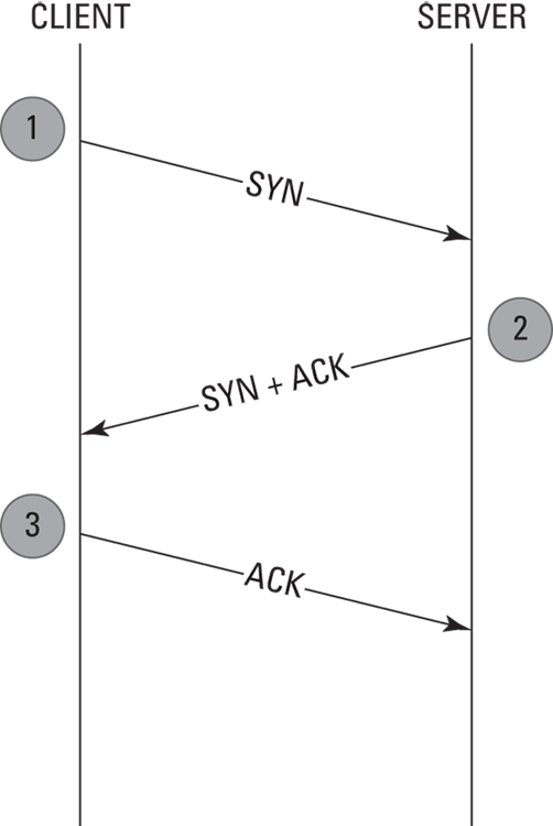
© John Wiley & Sons, Inc.
FIGURE 6-3: The TCP three-way handshake.
A socket is a logical endpoint on a system or device used to communicate over a network to another system or device (or even on the same device). A socket usually is expressed as an IP address and port number, such as 192.168.100.2:25.
- User Datagram Protocol (UDP): A connectionless protocol that provides fast best-effort delivery of datagrams across a network. A connectionless protocol doesn’t guarantee delivery of transmitted packets (datagrams) and is thus considered unreliable. It doesn’t
- Attempt to establish a connection with the destination network prior to transmitting data
- Acknowledge received datagrams
- Perform re-sequencing
- Perform error checking or recovery
- A datagram is a self-contained unit of data that is capable of being routed between a source and a destination. Similar to a packet, which is used in the Internet Protocol (IP), datagrams are commonly used in UDP and other protocols. The term Protocol Data Unit (PDU) is used to describe the unit of data used at a particular layer of a protocol. In OSI, the Layer 1 PDU is a bit, Layer 2’s PDU is a frame, Layer 3’s is a packet, and Layer 4’s is a segment or datagram, and Layer 7’s is message.
UDP is ideally suited for data that requires fast delivery as long as that data isn’t sensitive to packet loss and doesn’t need to be fragmented. Examples of applications that use UDP include Domain Name System, Simple Network Management Protocol, and streaming audio or video. The following characteristics and features are associated with UDP:
- Connectionless: Doesn’t pre-establish a communication circuit with the destination network
- Best effort: Doesn’t guarantee delivery and thus is considered to be unreliable
- Fast: Has no overhead associated with circuit establishment, acknowledgement, sequencing, or error-checking and recovery
Jitter in streaming audio and video is caused by variations in the delay of received packets, which is a negative characteristic of UDP. Sequenced Packet Exchange (SPX): The protocol used to guarantee data delivery in older Novell NetWare IPX/SPX networks. SPX sequences transmitted packets, reassembles received packets, confirms that all packets are received, and requests retransmission of packets that aren’t received. SPX is to IPX as TCP is to IP, though the order is stated as IPX/SPX rather than SPX/IPX (as in TCP/IP): SPX and TCP are Layer 4 protocols, and IPX and IP are Layer 3 protocols. Just think of the SPX-IPS and TCP-IP relationships as yang and yin, rather than yin and yang!
Several examples of connection-oriented and connectionless-oriented protocols are identified in Table 6-1.
- Secure Sockets Layer/Transport Layer Security (SSL/TLS): The SSL/TLS protocol provides session-based encryption and authentication for secure communication between clients and servers on the Internet. SSL/TLS provides server authentication with optional client authentication.
- Stream Control Transmission Protocol (SCTP): A message-oriented protocol (similar to UDP) that ensures reliable, in-sequence transport with congestion control (similar to TCP). SCTP also provides multihoming and redundant paths for resiliency and reliability.
TABLE 6-1 Connection-Oriented and Connectionless-Oriented Protocols
Protocol |
Layer |
Type |
|---|---|---|
TCP (Transmission Control Protocol) |
4 (Transport) |
Connection-oriented |
UDP (User Datagram Protocol) |
4 (Transport) |
Connectionless-oriented |
IP (Internet Protocol) |
3 (Network) |
Connectionless-oriented |
ICMP (Internet Control Message Protocol) |
3 (Network) |
Connectionless-oriented |
IPX (Internetwork Packet Exchange) |
3 (Network) |
Connectionless-oriented |
SPX (Sequenced Packet Exchange) |
4 (Transport) |
Connection-oriented |
Network Layer (Layer 3)
The Network Layer (Layer 3) provides routing and related functions that enable data to be transported between systems on the same network or on interconnected networks (or internetworks). Routing protocols — such as the Routing Information Protocol (RIP), Open Shortest Path First (OSPF), and Border Gateway Protocol (BGP) — are defined at this layer. Logical addressing of devices on the network is accomplished at this layer by using routed protocols, including IP and Internetwork Packet Exchange (IPX).
The Network Layer is responsible primarily for routing. Routing protocols move routed protocol messages across a network. Routing protocols include RIP, OSPF, IS-IS, IGRP, and BGP. Routed protocols include IP and IPX.
ROUTING PROTOCOLS
Routing protocols are defined at the Network Layer and specify how routers communicate with one another on a WAN. Routing protocols are classified as static or dynamic.
A static routing protocol requires an administrator to create and update routes manually on the router. If the route is down, the network is down. The router can’t reroute traffic dynamically to an alternative destination (unless a different route is specified manually). Also, if a given route is congested, but an alternative route is available and relatively fast, the router with static routes can’t route data dynamically over the faster route. Static routing is practical only on very small networks or for very limited, special-case routing scenarios (such as a destination that’s reachable only via a single router). Despite the limitations of static routing, it has a few advantages, such as low bandwidth requirements (routing information isn’t broadcast across the network) and some built-in security (users can get only to destinations that are specified in the routing table).
A dynamic routing protocol can discover routes and determine the best route to a given destination at any given time. The routing table is periodically updated with current routing information. Dynamic routing protocols are further classified as link-state and distance-vector (for intradomain routing) and path-vector (for interdomain routing) protocols.
A distance-vector protocol makes routing decisions based on two factors: the distance (hop count or other metric) and vector (the egress router interface). It periodically informs its peers and/or neighbors of topology changes. Convergence — the time it takes for all routers in a network to update their routing tables with the most current information, such as link status changes — can be a significant problem for distance-vector protocols. Without convergence, some routers in a network may be unaware of topology changes, causing the router to send traffic to an invalid destination. During convergence, routing information is exchanged between routers, and the network slows considerably.
Routing Information Protocol (RIP) is a distance-vector routing protocol that uses hop count as its routing metric. To prevent routing loops, in which packets effectively get stuck bouncing between various router nodes, RIP implements a hop limit of 15, which significantly limits the size of networks that RIP can support. After a data packet crosses 15 router nodes (hops) between a source and a destination, the destination is considered to be unreachable. In addition to hop limits, RIP employs three mechanisms to prevent routing loops:
- Split horizon: Prevents a router from advertising a route back out through the same interface from which the route was learned.
- Route poisoning: Sets the hop count on a bad route to 16, effectively advertising the route as unreachable if it takes more than 15 hops to reach.
- Holddown timers: Cause a router to start a timer when the router first receives information that a destination is unreachable. Subsequent updates about that destination will not be accepted until the timer expires. This mechanism also helps prevent problems associated with flapping, which occurs when a route (or interface) changes state (up, down, up, down) repeatedly over a short period.
RIP uses UDP port 520 as its transport protocol and port; thus, it is a connectionless-oriented protocol. Other disadvantages of RIP include slow convergence and insufficient security. (RIPv1 has no authentication, and RIPv2 transmits passwords in cleartext.) RIP is a legacy protocol, but it’s still in widespread use on networks today despite its limitations, because of its simplicity.
Hop count generally refers to the number of router nodes that a packet must pass through to reach its destination.
A link-state protocol requires every router to calculate and maintain a complete map, or routing table, of the entire network. Routers that use a link-state protocol periodically transmit updates that contain information about adjacent connections (called link states) to all other routers in the network. Link-state protocols are computation-intensive but can calculate the most efficient route to a destination, taking into account numerous factors such as link speed, delay, load, reliability, and cost (an arbitrarily assigned weight or metric). Convergence occurs very rapidly (within seconds) with link-state protocols; distance-vector protocols usually take longer (several minutes or even hours in very large networks). Two examples of link-state routing protocols are
- Open Shortest Path First (OSPF): OSPF is a link-state routing protocol widely used in large enterprise networks. It’s considered to be an interior gateway protocol because it performs routing within a single autonomous system. OSPF is encapsulated directly into IP datagrams, as opposed to using a Transport Layer protocol such as TCP or UDP. OSPF networks are divided into areas identified by 32-bit area identifiers. Area identifiers can (but don’t have to) correspond to network IP addresses and can duplicate IP addresses without conflicts. Special OSPF areas include the backbone area (also known as area 0), stub area, and not-so-stubby area.
- Intermediate System to Intermediate System (IS-IS): IS-IS is a link-state routing protocol used to route datagrams through a packet-switched network. This interior gateway protocol is used for routing within an autonomous system and is, used extensively in large service-provider backbone networks.
An autonomous system (AS) is a group of contiguous IP address ranges under the control of a single Internet entity. Individual autonomous systems are assigned a 16-bit or 32-bit number (ASN) that uniquely identifies the network on the Internet, assigned by the Internet Assigned Numbers Authority (IANA).
A path-vector protocol is similar in concept to a distance-vector protocol, but without the scalability issues associated with limited hop counts. Border Gateway Protocol (BGP) is an example of a path-vector protocol. BGP is a path-vector routing protocol used between separate autonomous systems. It’s considered to be an exterior gateway protocol because it performs routing between separate autonomous systems. It’s the core protocol used by Internet service providers, network service providers, and very large private IP networks. When BGP runs between autonomous systems, it’s called external BGP (eBGP). When BGP runs within an autonomous system (such as on a private IP network), it’s called internal BGP (iBGP).
ROUTED PROTOCOLS
Routed protocols are Network Layer protocols, such as Internetwork Packet Exchange (IPX) and IP, which address packets with routing information and allow those packets to be transported across networks via routing protocols (discussed in the preceding section).
Internetwork Packet Exchange (IPX) is a connectionless protocol used primarily in older Novell NetWare networks for routing packets across the network. It’s part of the Internetwork Packet Exchange/Sequenced Packet Exchange (IPX/SPX) protocol suite, which is analogous to the TCP/IP suite.
IP contains addressing information that enables packets to be routed. IP is part of the Transmission Control Protocol/Internet Protocol (TCP/IP) suite, which is the language of the Internet. IP has two primary responsibilities:
- Connectionless, best-effort (no guarantee of) delivery of datagrams
- Fragmentation and reassembly of datagrams
IP Version 4 (IPv4), which is currently the most commonly used version, uses a 32-bit logical IP address that’s divided into four 8-bit sections (octets) and consists of two main parts: the network number and the host number. The first four bits in an octet are known as the high-order bits, and the last four bits in an octet are known as the low-order bits. The first bit in the octet is referred to as the most significant bit, and the last bit in the octet is referred to as the least significant bit. Each bit position represents its value (see Table 6-2) if the bit is on (1); otherwise, its value is zero (off or 0).
TABLE 6-2 Bit Position Values in an IPv4 Address
High-Order Bits |
Low-Order Bits |
||||||
|---|---|---|---|---|---|---|---|
Most significant bit |
Least significant bit |
||||||
128 |
64 |
32 |
16 |
8 |
4 |
2 |
1 |
Each octet contains an 8-bit number with a value of 0 to 255. Table 6-3 shows a partial list of octet values in binary notation.
TABLE 6-3 Binary Notation of Octet Values
Decimal |
Binary |
Decimal |
Binary |
Decimal |
Binary |
|---|---|---|---|---|---|
255 |
1111 1111 |
200 |
1100 1000 |
9 |
0000 1001 |
254 |
1111 1110 |
180 |
1011 0100 |
8 |
0000 1000 |
253 |
1111 1101 |
160 |
1010 0000 |
7 |
0000 0111 |
252 |
1111 1100 |
140 |
1000 1100 |
6 |
0000 0110 |
251 |
1111 1011 |
120 |
0111 1000 |
5 |
0000 0101 |
250 |
1111 1010 |
100 |
0110 0100 |
4 |
0000 0100 |
249 |
1111 1001 |
80 |
0101 0000 |
3 |
0000 0011 |
248 |
1111 1000 |
60 |
0011 1100 |
2 |
0000 0010 |
247 |
1111 0111 |
40 |
0010 1000 |
1 |
0000 0001 |
246 |
1111 0110 |
20 |
0001 0100 |
0 |
0000 0000 |
IPv4 addressing supports five address classes, indicated by the high-order (leftmost) bits in the IP address, as listed in Table 6-4.
TABLE 6-4 IP Address Classes
Class |
Purpose |
High-Order Bits |
Address Range |
Maximum Number of Hosts |
|---|---|---|---|---|
A |
Large networks |
0 |
1 to 126 |
16,777,214 (224-2) |
B |
Medium networks |
10 |
128 to 191 |
65,534 (216-2) |
C |
Small networks |
110 |
192 to 223 |
254 (28-2) |
D |
Multicast |
1110 |
224 to 239 |
N/A |
E |
Experimental |
1111 |
240 to 254 |
N/A |
The address range 127.0.0.1 to 127.255.255.255 is a loopback network used for testing and troubleshooting. Packets sent to a 127 address are immediately routed back to the source device. The most commonly used loopback (or localhost) address for devices is 127.0.0.1 (sometimes called home), although any address in the 127 network range can be used for this purpose.
Several IPv4 address ranges are also reserved for use in private networks, including
- 10.0.0.0–10.255.255.255 (Class A)
- 172.16.0.0–172.31.255.255 (Class B)
- 192.168.0.0–192.168.255.255 (Class C)
These addresses aren’t routable on the Internet and thus are often implemented behind firewalls and gateways by using Network Address Translation (NAT) to conserve IP addresses, mask the network architecture, and enhance security. NAT translates private, non-routable addresses on internal network devices to registered IP addresses when communication across the Internet is required. The widespread use of NAT and private network addresses somewhat delayed the inevitable depletion of IPv4 addresses, which is limited to approximately 4.3 billion due to its 32-bit format (232 = 4,294,967,296 possible addresses). But the thing about inevitability is that it’s … well, inevitable. Factors such as the proliferation of mobile devices worldwide, always-on Internet connections, inefficient use of assigned IPv4 addresses, and the spectacular miscalculation of IBM’s Thomas Watson — who in 1943 predicted that there would be a worldwide market for “maybe five computers” (he was no Nostradamus) — have led to the depletion of IPv4 addresses.
Technically, we’re not completely out of IPv4 addresses. Each regional Internet registry has reserved a very small pool of IPv4 addresses to facilitate the transition to IPv6.
In 1998, the IETF formally defined IP Version 6 (IPv6) as the replacement for IPv4. IPv6 uses a 128-bit hexadecimal IP address (versus 32 bits for IPv4) and incorporates additional functionality to provide security, multimedia support, plug-and-play compatibility, and backward compatibility with IPv4. The main reason for developing IPv6 was to provide infinitely more network addresses than are available with IPv4 addresses. Okay, it’s not infinite, but it is ginormous — 2128 or approximately 3.4 × 1038 (that’s 340 hundred undecillion) unique addresses!
IPv6 addresses consist of 32 hexadecimal numbers grouped into eight blocks (sometimes referred to as hextels) of four hexadecimal digits, separated by a colon.
A hexadecimal digit is represented by 4 bits (see Table 6-5), so each hextel is 16 bits (four 4-bit hexadecimal digits), and eight 16-bit hextels equals 128 bits. An IPv6 address is further divided into two 64-bit segments. The first (also referred to as the top or upper) 64 bits represent the network part of the address, and the last (also referred to as the bottom or lower) 64 bits represent the node or interface part of the address. The network part is further subdivided into a 48-bit global network address and a 16-bit subnet. The node or interface part of the address is based on the IEEE Extended Unique Identifier (EUI-64) physical or media access control (MAC) address (discussed in the “Data Link Layer (Layer 2)” section later in this chapter) of the node or interface.
TABLE 6-5 Decimal, Hexadecimal, and Binary Notation
Decimal |
Hexadecimal |
Binary |
|---|---|---|
0 |
0 |
0000 |
1 |
1 |
0001 |
2 |
2 |
0010 |
3 |
3 |
0011 |
4 |
4 |
0100 |
5 |
5 |
0101 |
6 |
6 |
0110 |
7 |
7 |
0111 |
8 |
8 |
1000 |
9 |
9 |
1001 |
10 |
A |
1010 |
11 |
B |
1011 |
12 |
C |
1100 |
13 |
D |
1101 |
14 |
E |
1110 |
15 |
F |
1111 |
The basic format for an IPv6 address is
xxxx:xxxx:xxxx:xxxx:xxxx:xxxx:xxxx:xxxx
where x represents a hexadecimal digit (0–f).
Following is an example of an IPv6 address:
2001:0db8:0000:0000:0008:0800:200c:417a
There are several rules the IETF has defined to shorten an IPv6 address:
- Leading zeroes in an individual hextel can be omitted, but there must be at least one hexadecimal digit in each hextel (except as noted in the next rule). Applying this rule to the previous example yields the following result: 2001:db8:0:0:8:800:200c:417a.
- Two colons (::) can be used to represent one or more groups of 16 bits of zeros, as well as leading or trailing zeroes in an address, and can only appear once in an IPv6 address. Applying this rule to the previous example yields the following result: 2001:db8::8:800:200c:417a.
- In mixed IPv4 and IPv6 environments, the form x:x:x:x:x;x:d.d.d.d can be used, in which x represents the six high-order 16-bit hextels of the address and d represents the four low-order 8-bit octets (in standard IPv4 notation) of the address. 0db8:0:0:0:0:FFFF:129.144.52.38 is a valid IPv6 address. Applying the previous two rules to this example yields the following result: db8::ffff:129.144.52.38.
Letters in hexadecimal notation are not case-sensitive (A is the same as a, B is the same as b, and so on), so either form can be used in IPv6 addresses, although IETF recommends using lowercase letters.
Security features in IPv6 include network-layer security via Internet Protocol Security and requirements defined in Request For Comments 7112 to prevent fragmentation exploits in IPv6 headers.
Although you don’t need to know all the intricate details of IPv6 addressing for the CISSP exam, as its use becomes more commonplace — particularly in Internet of Things (IoT) devices — you need to be familiar with the security enhancements in IPv6 and be able to recognize a valid IPv6 address.
IMPLICATIONS OF MULTILAYER PROTOCOLS
Multilayer protocols are groups of protocols that are purpose-built for some type of specialized communications need. Multilayer protocols have their own schemes for encapsulation, like TCP/IP itself.
One good example of a multilayer protocol is Distributed Network Protocol (DNP3), which is used in industrial control systems (ICS) and supervisory control and data acquisition (SCADA) networks. DNP3 has a Data Frame Layer, Transport Layer, and Application Layer.
DNP3’s original design lacks security features, such as authentication and encryption. Recent updates to the standard have introduced security protocols. Without security features, relatively simple attacks (such as eavesdropping, spoofing, and perhaps denial of service) can be carried out easily on specialized multiprotocol networks.
CONVERGED PROTOCOLS
Converged protocols refers to an implementation of two or more protocols for a specific communications purpose. Examples of converged protocols include
- Multiprotocol Label Switching (MPLS)
- Fibre Channel over Ethernet (FCoE)
- Voice over Internet Protocol (VoIP)
- Session Initiation Protocol (SIP)
- Internet Small Computer System Interface (iSCSI)
SOFTWARE-DEFINED NETWORKS
Software-defined networks (SDN) represent the ability to create, configure, manage, secure, and monitor network elements rapidly and efficiently. SDN uses an open standards architecture that enables intelligent network functions, such as routing, switching, and load balancing (the overlay function), to be performed on virtual software that is installed on commodity network hardware (the physical underlay), similar to server virtualization. In SDN, network elements and network architectures are virtual, which enables organizations to build and modify their networks and network elements quickly.
As with other virtualization technologies, correct management of SDN requires policy, process, and discipline to avoid network sprawl (the phenomenon in which undisciplined administrators bypass change control processes and unilaterally create virtual network elements).
Related to SDN, software-defined WAN is discussed later in this chapter.
IPSEC
Internet Protocol Security (IPsec) is an IETF open standard for VPNs that operates at the Network Layer (Layer 3) of the OSI model. It’s the most popular and robust VPN protocol in use today. IPsec ensures confidentiality, integrity, and authenticity by using Layer 3 encryption and authentication to provide an end-to-end solution. IPsec operates in two modes:
- Transport: Only the data is encrypted.
- Tunnel: The entire packet is encrypted.
The two modes of IPsec are Transport mode (on the LAN) and Tunnel mode (on the WAN).
The two main protocols used in IPsec are
- Authentication Header (AH): Provides integrity, authentication, and nonrepudiation
- Encapsulating Security Payload (ESP): Provides confidentiality (encryption) and limited authentication
Each pair of hosts communicating in an IPsec session must establish a security association (SA), which is a one-way connection between two communicating parties; thus, two associations are required for each pair of communicating hosts. Additionally, each association supports only a single protocol (AH or ESP). Therefore, using both an AH and an ESP between two communicating hosts requires four security associations. A security association has three parameters that uniquely identify it in an IPsec session:
- Security Parameter Index (SPI): The SPI is a 32-bit string used by the receiving station to differentiate between SAs terminating on that station. The SPI is located within the AH or ESP header.
- Destination IP address: The destination address could be the end station or an intermediate gateway or firewall, but it must be a unicast address.
- Security Protocol ID: The Security Protocol ID must be an AH or ESP association.
In IPsec, a security association is a one-way connection. You need a minimum of two security associations for two-way communications.
Key management is provided in IPsec by using the Internet Key Exchange (IKE), which is a combination of three complementary protocols: the Internet Security Association and Key Management Protocol (ISAKMP), the Secure Key Exchange Mechanism, and the Oakley Key Exchange Protocol. Internet Key Exchange operates in three modes: Main, Aggressive, and Quick.
OTHER NETWORK LAYER PROTOCOLS
Other protocols defined at the Network Layer include Internet Control Message Protocol (ICMP) and Simple Key Management for Internet Protocols (SKIP).
ICMP is used for network control and diagnostics. Commonly used ICMP commands include ping and traceroute. Although ICMP is very helpful in troubleshooting routing and connectivity issues in a network, it is also commonly used by attackers for network reconnaissance, device discovery, and denial-of-service (DoS) attacks (such as an ICMP flood).
SKIP is a Network Layer key management protocol used to share encryption keys. An advantage of SKIP is that it doesn't require a communication session to be established before it sends encrypted keys or packets. The protocol is bandwidth-intensive, however, because of the size of additional header information in encrypted packets.
NETWORKING EQUIPMENT AT THE NETWORK LAYER
The primary networking equipment defined at Layer 3 is routers and gateways.
Routers are intelligent devices that link dissimilar networks and use logical or physical addresses to forward data packets only to the destination network (or along the network path). Routers employ various routing algorithms (such as RIP, OSPF, and BGP) to determine the best path to a destination, based on variables that include bandwidth, cost, delay, and distance.
Gateways are created with software running on a computer (workstation or server) or router. Gateways link dissimilar programs and protocols by examining the entire Layer 7 data packet so as to translate incompatibilities. A gateway can be used, for example, to link an IP network to an IPX network or a Microsoft Exchange mail server to a Lotus Notes server (a mail gateway).
Data Link Layer (Layer 2)
The Data Link Layer ensures that messages are delivered to the proper device across a physical network. This layer also defines the networking protocol (such as Ethernet, USB, Wi-Fi, or token ring) used to send and receive data between individual devices. The Data Link Layer formats messages from layers above into frames for transmission, handles point-to-point synchronization and error control, and can perform link encryption.
The IEEE 802 standards and protocols further divide the Data Link Layer into two sublayers: Logical Link Control (LLC) and Media Access Control (MAC), as shown in Figure 6-4.

© John Wiley & Sons, Inc.
FIGURE 6-4: The LLC and MAC sublayers.
The Data Link Layer is responsible for ensuring that messages are delivered to the proper device across a physical network.
The LLC sublayer operates between the Network Layer above and the MAC sublayer below. The LLC sublayer performs the following three functions:
- Provides an interface for the MAC sublayer by using Source Service Access Points and Destination Service Access Points.
- Manages the control, sequencing, and acknowledgement of frames being passed up to the Network Layer or down to the Physical Layer.
- Bears responsibility for timing and flow control. Flow control monitors the flow of data between devices to ensure that a receiving device, which may not necessarily be operating at the same speed as the transmitting device, isn’t overwhelmed and dropping packets.
LLC and MAC are sublayers of the Data Link Layer.
The MAC sublayer operates between the LLC sublayer above and the Physical Layer below. It’s responsible primarily for framing and has the following three functions:
- Performs error control: Error control uses a cyclic redundancy check (CRC), a simple mathematical calculation or checksum used to create a message profile. The CRC is recalculated by the receiving device. If the calculated CRC doesn’t match the received CRC, the packet is dropped, and a request to resend is transmitted back to the device that sent it.
- Identifies hardware device (or MAC) addresses: A MAC address (also known as a hardware address or physical address) is a 48-bit address that’s encoded on each device by its manufacturer. The first 24 bits identify the manufacturer or vendor. The second 24 bits uniquely identify the device.
- Controls media access: The three basic types of media access are
- Contention: In contention-based networks such as Ethernet, individual devices must vie for control of the physical network medium. This type of access is ideally suited to networks characterized by small bursts of traffic. Ethernet networks use a contention-based method, known as Carrier Sense Multiple Access with Collision Detection (CSMA/CD), in which all stations listen for traffic on the physical network medium. If the line is clear, any station can transmit data. If another station attempts to transmit data at the same time, a collision occurs, the traffic is dropped, and both stations must wait a random period of time before attempting to retransmit. Another method, used in Wi-Fi networks, is known as Carrier Sense Multiple Access with Collision Avoidance (CSMA/CA). Unlike CSMA/CD, CSMA/CA prevents collisions from occurring in the first place. This is accomplished by listening for traffic on the network. If the network is clear (or idle), a station waits a period of time (known as the inter-frame gap, or IFG) and then sends a frame. The sender station then sets a timer and waits for acknowledgement from the receiver that the frame was successfully received. If the acknowledgement is not received, the sender waits for a back-off time period and then re-transmits the frame.
- Token passing: In token-passing networks such as token ring and Fiber Distributed Data Interface (FDDI), individual devices must wait for a special frame, known as a token, before they transmit data across the physical network medium. This type of network is considered to be deterministic (transmission delay can be reliably calculated, and collisions don’t occur) and is ideally suited for networks that have large, bandwidth-consuming applications that are delay-sensitive. Token ring, FDDI, and ARCnet networks use various token-passing methods for media access control.
- Polling: In polling networks, individual devices (secondary hosts) are polled by a primary host to see whether they have data to be transmitted. Secondary hosts can’t transmit until permission is granted by the primary host. Polling is typically used in mainframe environments and on wireless networks.
LAN PROTOCOLS AND TRANSMISSION METHODS
Common LAN protocols are defined at the Data Link and Physical layers, and include the following:
- Ethernet: The Ethernet protocol transports data to the physical LAN medium by using CSMA/CD (discussed in the preceding section). It is designed for networks characterized by sporadic, sometimes heavy traffic requirements. Ethernet is by far the most common LAN protocol used today, most often implemented with twisted-pair cabling (discussed in the section “Cable and connector types”). Ethernet operates at speeds up to 10 Mbps, Fast Ethernet operates at speeds up to 100 Mbps (over Cat 5 twisted-pair or fiber-optic cabling), and Gigabit Ethernet operates at speeds up to 40 Gbps (over Cat 5e, Cat 6, or Cat 7 twisted-pair or fiber-optic cabling).
- ARCNET: The Attached Resource Computer NETwork (ARCNET) protocol is one of the earliest LAN technologies developed. It transports data to the physical LAN medium by using the token-passing media access method that we discuss in the preceding section. It’s implemented in a star topology by using coaxial cable. ARCNET provides slow but predictable network performance.
- Token ring: The token ring protocol transports data to the physical LAN medium by using the token-passing media access method that we discuss in the preceding section. In a token ring network, all nodes are attached to a Multistation Access Unit (MAU) in a logical ring (but physical star) topology. One node on the token ring network is designated as the active monitor and ensures that no more than one token is on the network at any given time. (Variations permit more than one token on the network.) If the token is lost, the active monitor is responsible for ensuring that a replacement token is generated. Token ring networks operate at speeds of 4 and 16 Mbps — pretty slow by today’s standards. Token ring networks are rarely seen nowadays.
- Fiber Distributed Data Interface (FDDI): The FDDI protocol transports data to the physical LAN medium by using the token-passing media access method that we discuss in the preceding section. It’s implemented as a dual counter-rotating ring over fiber-optic cabling at speeds up to 100 Mbps. All stations on a FDDI network are connected to both rings. During normal operation, only one ring is active. In the event of a network break or fault, the ring wraps back through the nearest node onto the second ring.
- Address Resolution Protocol (ARP): ARP maps Network Layer IP addresses to MAC addresses. ARP discovers physical addresses of attached devices by broadcasting ARP query messages on the network segment. Then IP-address-to-MAC-address translations are maintained in a dynamic table that’s cached on the system.
- Reverse Address Resolution Protocol (RARP): RARP maps MAC addresses to IP addresses. This process is necessary when a system, such as a diskless machine, needs to discover its IP address. The system broadcasts a RARP message that provides the system’s MAC address and requests to be informed of its IP address. A RARP server replies with the requested information.
Both ARP and RARP are Layer 2 protocols. ARP maps an IP address to a MAC address and is used to identify a device’s hardware address when only the IP address is known. RARP maps a MAC address to an IP address and is used to identify a device’s IP address when only the MAC address is known.
LAN data transmissions are classified as
- Unicast: Packets are sent from the source to a single destination device by using a specific destination IP address.
- Multicast: Packets are copied and sent from the source to multiple destination devices by using a special multicast IP address that the destination stations have been specifically configured to use.
- Anycast: Packets are copied and sent from the source to a single destination IP address that is shared by several devices in multiple locations. Anycast is commonly used in CDNs (discussed earlier in this chapter).
- Broadcast: Packets are copied and sent from the source to every device on a destination network by using a broadcast IP address.
LAN data transmissions are classified as unicast, multicast, or broadcast.
WIRELESS NETWORKS
Important wireless networks to be familiar with for the CISSP exam include Li-Fi, Wi-Fi, Near-Field Communication (NFC), ZigBee, and satellite.
Similar to fiber-optic networks, which use light rather than electrical signals to transmit data over wired networks, Li-Fi uses light in the visible, ultraviolet, and infrared spectrums rather than radio frequency to transmit data up to 100 Gbps over wireless networks.
WLAN (wireless LAN) technologies, commonly known as Wi-Fi, function at the lower layers of the OSI Reference Model. WLAN protocols define how frames are transmitted over the air. See Table 6-6 for a description of the most common IEEE 802.11 WLAN standards.
TABLE 6-6 Wireless LAN Standards
Type |
Speed |
Description |
|---|---|---|
802.11a |
54 Mbps |
Operates at 5 GHz (less interference than at 2.4 GHz) |
802.11b |
11 Mbps |
Operates at 2.4 GHz (first widely used protocol) |
802.11g |
54 Mbps |
Operates at 2.4 GHz (backward-compatible with 802.11b) |
802.11n |
600 Mbps |
Operates at 5 GHz or 2.4 GHz |
802.11ac |
1 Gbps |
Operates at 5 GHz |
802.11ad (WiGig) |
6.7 Gbps |
Operates at 60 GHz (range limited to 30 ft) |
802.11ah (WiFi HaLow) |
347 Mbps |
Operates at 900 MHz |
802.11ax (WiFi 6) |
10 Gbps |
Operates at 5 GHz or 2.4 GHz (backwards-compatible with 802.11a/b/g/n/ac) |
ZigBee is a low-cost, low-power wireless mesh network protocol based on the IEEE 802.15.4 standard. ZigBee is commonly used in industrial environments and smart home products. Various ZigBee specifications include ZigBee Pro, ZigBee Radio Frequency for Consumer Electronics (RF4CE), and ZigBee IP.
Near-Field Communication (NFC) is a set of communication protocols used over short distances (up to 4 cm), often used with smartphones for access control and contactless payments.
SATELLITE NETWORKS
Satellite broadband technologies are commonly used in remote areas where wired, wireless, or cellular services may not be readily available, as well as to provide backup connectivity. Other applications include providing connectivity for logistics (ships, planes, and trains) and communication backbones for IoT devices (such as fleet management and remote maintenance).
CELLULAR NETWORKS
Smartphones, IoT devices, and other mobile devices use cellular networks as well as Wi-Fi networks to communicate. The Third Generation Partnership Project defines the various generations and develops the protocols for mobile telecommunications (that is, cellular networks). The International Telecommunication Union (ITU) is a regulatory organization of the United Nations that is responsible for the global use of mobile telecommunication. Relevant cellular network generations include
- 3G: The first 3G networks provided minimum information transfer rates of 200 kilobits per second (Kbps). The ITU has never formally defined a standard for 3G data rates, so downlink data speeds vary widely from 384 Kbps for Wideband Code Division Multiple Access (W-CDMA) to 168 Mbps for Advanced Evolved High Speed Packet Access (HSPA+). 3G cellular networks are still commonly used in many countries and are increasingly being used as offload networks for 4G and 5G, as well as IoT applications.
- 4G: 4G Long-Term Evolution (LTE) mobile networks are currently the most commonly deployed cellular networks used for mobile technology. LTE networks are built on packet-switched all-IP core networks. LTE Advanced and LTE Advanced Pro have theoretical peak data rates of 1 Gbps and 3 Gbps, respectively.
- 5G: 5G networks deliver significantly higher speeds and lower latency than previous generations but also introduce many other important innovations to support a wide variety of use cases, including massive Machine-Type Communications (mMTC), Ultra Reliable and Low Latency Communication (URLLC), and enhanced Mobile Broadband (eMBB).
WAN TECHNOLOGIES AND PROTOCOLS
WAN technologies function at the lower three layers of the OSI Reference Model (the Physical, Data Link, and Network layers), primarily at the Data Link Layer. WAN protocols define how frames are carried across a single data link between two devices. These protocols include
- Point-to-point links: These links provide a single, pre-established WAN communications path from the customer’s network across a carrier network (such as a Public Switched Telephone Network (PSTN)) to a remote network. These point-to-point links include
- Layer 2 Forwarding Protocol (L2F): A tunneling (data encapsulation) protocol developed by Cisco and used to implement VPNs, specifically Point-to-Point Protocol (discussed later in this section) traffic. L2F provides encapsulation but doesn’t provide encryption or confidentiality.
- Layer 2 Tunneling Protocol (L2TP): A tunneling protocol used to implement VPNs. L2TP is derived from L2F (described in the preceding item) and PPTP (described in this list) and uses UDP port 1701 (see the section “Network Layer [Layer 3]” earlier in this chapter) to create a tunneling session. L2TP is commonly implemented along with an encryption protocol, such as IPsec, because it doesn’t encrypt traffic or provide confidentiality by itself. We discuss L2TP and IPsec in more detail in the section “Remote access” later in this chapter.
- Point-to-Point Protocol (PPP): The successor to SLIP (see the discussion later in this section), PPP provides router-to-router and host-to-network connections over synchronous and asynchronous circuits. It’s a more robust protocol than SLIP and provides additional built-in security mechanisms. PPP is far more common than SLIP in modern networking environments.
- Point-to-Point Tunneling Protocol (PPTP): A tunneling protocol developed by Microsoft and commonly used to implement VPNs, specifically PPP traffic. PPTP doesn’t provide encryption or confidentiality, instead relying on other protocols, such as PAP, CHAP, and EAP, for security. We discuss PPTP, PAP, CHAP, and EAP in more detail in the section “Remote access” later in this chapter.
- Serial Line IP (SLIP): The predecessor of PPP, SLIP was originally developed to support TCP/IP networking over low-speed asynchronous serial lines (such as dial-up modems) for Berkeley Unix computers. SLIP is rarely seen today except in computer museums.
- Circuit-switched networks: In a circuit-switched network, a dedicated physical circuit path is established, maintained, and terminated between the sender and receiver across a carrier network for each communications session (the call). This network type is used extensively in telephone company networks and functions similarly to a regular telephone call. Examples include
- Digital Subscriber Line (xDSL): xDSL uses existing analog phone lines to deliver high-bandwidth connectivity to remote customers.
Integrated Services Digital Network (ISDN): ISDN is a communications protocol that operates over analog phone lines that have been converted to use digital signaling. ISDN lines are capable of transmitting both voice and data traffic. ISDN defines a B-channel for data, voice, and other services, and a D-channel for control and signaling information.
With the introduction and widespread adoption of DSL and DOCSIS, ISDN has largely fallen out of favor in the United States and is no longer available in many areas.
- Circuit-switched networks are ideally suited for always-on connections that experience constant traffic.
Packet-switched networks: In a packet-switched network, devices share bandwidth (by using statistical multiplexing) on communications links to transport packets between a sender and receiver across a carrier network. This type of network is more resilient to error and congestion than circuit-switched networks. We compare packet-switched and circuit-switched networks in Table 6-7.
Examples of packet-switched networks include
- Asynchronous Transfer Mode (ATM): A very high-speed, low-delay technology that uses switching and multiplexing techniques to rapidly relay fixed-length (53-byte) cells that contain voice, video, or data. Cell processing occurs in hardware that reduces transit delays. ATM is ideally suited for fiber-optic networks that carry bursty (uneven) traffic.
- Data Over Cable Service Interface Specification (DOCSIS): A communications protocol for transmitting high-speed data over an existing cable TV system.
- Frame Relay: A packet-switched standard protocol that handles multiple virtual circuits by using High-level Data Link Control encapsulation (which we discuss later in this section) between connected devices. Frame Relay uses a simplified framing approach that has no error correction and Data Link Connection Identifiers to achieve high speeds across the WAN. Frame Relay can be used on Switched Virtual Circuits (SVCs) or Permanent Virtual Circuits (PVCs). An SVC is a temporary connection that’s dynamically created (in the circuit establishment phase) to transmit data (which happens during the data transfer phase) and then disconnected (in the circuit termination phase). PVCs are permanently established connections. Because the connection is permanent, a PVC doesn’t require the bandwidth overhead associated with circuit establishment and termination. PVCs are generally more expensive than SVCs.
- Multi-Protocol Label Switching (MPLS): A packet-switched, high-speed, highly scalable, highly versatile technology used to create fully meshed VPNs. It can carry IP packets as well as ATM, SONET (Synchronous Optical Networking), or Ethernet frames. MPLS is specified at both Layer 2 and Layer 3. Label Edge Routers (LERs) in an MPLS network push or encapsulate a packet (or frame) with an MPLS label. The label information is used to switch the payload through the MPLS cloud at very high speeds. Label Switch Routers within the MPLS cloud make routing decisions based solely on the label information without actually examining the payload. At the egress point, an LER pops (decapsulates) the packet, removing the MPLS label when the packet exits the MPLS network. One advantage of an MPLS network is that a customer loses visibility into the cloud. If you’re a glass-half-full type, one advantage of an MPLS network is that an attacker loses visibility into the cloud.
- Synchronous Optical Network (SONET) and Synchronous Digital Hierarchy (SDH): A high-availability, high-speed, multiplexed, low-latency technology used on fiber-optic networks. SONET was originally designed for the public telephone network and is widely used throughout the United States and Canada, particularly within the energy industry. SDH was developed after SONET and is used throughout the rest of the world. Data rates for SONET and SDH are defined at optical carrier (OC) levels (see Table 6-8).
- Switched Multimegabit Data Service (SMDS): A high-speed, packet-switched, connectionless-oriented, datagram-based technology available over public switched networks. Typically, companies that exchange large amounts of data bursts with other remote networks use SMDS.
- X.25: The first packet-switching network, X.25 is an International Telecommunication Union – Telecommunications (ITU-T) standard that defines how point-to-point connections between data terminal equipment (DTE) and data carrier equipment (DCE) are established and maintained. X.25 specifies the Link Access Procedure, Balanced (LAPB) protocol at the Data Link Layer and the Packet Level Protocol (PLP; also known as X.25 Level 3) at the Network Layer. X.25 is more common outside the United States but largely has been superseded by MPLS and Frame Relay.
Packet-switched networks are ideally suited for on-demand connections that have bursty traffic.- Other WAN protocols: Two other important WAN protocols defined at the Data Link Layer include
- High-level Data Link Control (HDLC): A bit-oriented, synchronous protocol that was created by the ISO to support point-to-point and multipoint configurations. Derived from SDLC, it specifies a data encapsulation method for synchronous serial links and is the default for serial links on Cisco routers. Unfortunately, various vendor implementations of the HDLC protocol are incompatible.
- Synchronous Data Link Control (SDLC): A bit-oriented, full-duplex serial protocol that was developed by IBM to facilitate communications between mainframes and remote offices. It defines and implements a polling method of media access, in which the primary (front end) polls the secondaries (remote stations) to determine whether communication is required.
WAN protocols and technologies are implemented over telecommunications circuits. Refer to Table 6-8 for a description of common telecommunications circuits and speeds.
TABLE 6-7 Circuit Switching versus Packet Switching
Circuit Switching |
Packet Switching |
|---|---|
Ideal for always-on connections, constant traffic, and voice communications |
Ideal for bursty traffic and data communications |
Connection-oriented |
Connectionless-oriented |
Fixed delays |
Variable delays |
TABLE 6-8 Common Telecommunications Circuits
Type |
Speed |
Description |
|---|---|---|
DS0 |
64 Kbps |
Digital Signal Level 0, framing specification used in transmitting digital signals over a single channel at 64 Kbps on a T1 facility |
DS1 |
1.544 Mbps or 2.048 Mbps |
Digital Signal Level 1, framing specification used in transmitting digital signals at 1.544 Mbps on a T1 facility (U.S.) or at 2.048 Mbps on an E1 facility (EU) |
DS3 |
44.736 Mbps |
Digital Signal Level 3, framing specification used in transmitting digital signals at 44.736 Mbps on a T3 facility |
T1 |
1.544 Mbps |
Digital WAN carrier facility; transmits DS1-formatted data at 1.544 Mbps (24 DS0 user channels at 64 Kbps each) |
T3 |
44.736 Mbps |
Digital WAN carrier facility; transmits DS3-formatted data at 44.736 Mbps (672 DS0 user channels at 64 Kbps each) |
E1 |
2.048 Mbps |
Wide-area digital transmission scheme used primarily in Europe that carries data at a rate of 2.048 Mbps |
E3 |
34.368 Mbps |
Wide-area digital transmission scheme used primarily in Europe that carries data at a rate of 34.368 Mbps (16 E1 signals) |
OC-1 |
51.84 Mbps |
SONET (Synchronous Optical Networking) Optical Carrier WAN specification |
OC-3 |
155.52 Mbps |
SONET |
OC-12 |
622.08 Mbps |
SONET |
OC-48 |
2.488 Gbps |
SONET |
OC-192 |
9.9 Gbps |
SONET |
OC-768 |
39 Gbps |
SONET |
NETWORKING EQUIPMENT AT THE DATA LINK LAYER
Networking devices that operate at the Data Link Layer include bridges, switches, DTEs/DCEs, and wireless equipment:
- A bridge is a semi-intelligent repeater used to connect two or more (similar or dissimilar) network segments. A bridge maintains an Address Resolution Protocol (ARP) cache that contains the MAC addresses of individual devices on connected network segments. When a bridge receives a data signal, it checks its ARP cache to determine whether the destination MAC address is on the local network segment. If the data signal turns out to be local, it isn’t forwarded to a different network. If the MAC address isn’t local, however, the bridge forwards (and amplifies) the data signal to all other connected network segments. A serious networking problem associated with bridges is a broadcast storm, in which broadcast traffic is automatically forwarded by a bridge, effectively flooding a network. Network bridges have been superseded by switches (discussed next).
- Data Terminal Equipment (DTE) is a general term used to classify devices at the user end of a user-to-network interface (such as computer workstations). A DTE connects to Data Carrier Equipment (DCE; also known as Data Circuit-Terminating Equipment), which consists of devices at the network end of a user-to-network interface. The DCE provides the physical connection to the network, forwards network traffic, and provides a clocking signal to synchronize transmissions between the DCE and the DTE. Examples of DCEs include NICs (Network Interface Cards), modems, and CSUs/DSUs (Channel Service Units/Data Service Units).
Wireless Access Points (APs) are transceivers that connect wireless clients to the wired network. Access points are base stations for the wireless network. They’re essentially hubs (or routers) operating in half-duplex mode — they can only receive or transmit at a given time; they can’t do both at the same time (unless they have multiple antennas). Wireless access points use antennas to transmit and receive data. The four basic types of wireless antennas are
- Omnidirectional: The most common type of wireless antenna, omnidirectional antennas are essentially short poles that transmit and receive wireless signals with equal strength in all directions around a horizontal axis. Omnidirectional antennas often employ a dipole design.
- Parabolic: Also known as dish antennas, parabolic antennas are directional dish antennas made of meshed wire grid or solid metal. Parabolic antennas are used to extend wireless ranges over great distances.
- Sectorized: Similar in shape to omnidirectional antennas, sectorized antennas have reflectors that direct transmitted signals in a specific direction (usually, a 60- to 120-degree pattern) to provide additional range and decrease interference in a specific direction.
- Yagi: Similar in appearance to a small aerial TV antenna, yagi antennas are used for long distances in point-to-point or point-to-multipoint wireless applications.
Client devices in a Wi-Fi network include desktop and laptop PCs, as well as mobile devices and other endpoints (such as smartphones, medical devices, bar-code scanners, and many so-called smart devices such as thermostats and other home automation devices). Wireless network interface cards (or wireless cards) come in a variety of forms, such as PCI adapters, PC cards, and USB adapters or are built into wireless-enabled devices, such as laptop PCs, tablets, and smartphones.
Access points and the wireless cards that connect to them must use the same WLAN 802.11 standard or be backward-compatible. See the section “Wireless networks” earlier in this chapter for a list of the 802.11 specifications.
Access points (APs) can operate in one of four modes:
- Root (also infrastructure): The default configuration for most APs. The AP is directly connected to the wired network, and wireless clients access the wired network via the wireless access point.
- Repeater (also stand-alone): The AP doesn’t connect directly to the wired network but provides an upstream link to another AP, effectively extending the range of the WLAN.
- Bridge: A rare configuration that isn’t supported in most APs. Bridge mode is used to connect two separate wired network segments via a wireless access point.
- Mesh: Multiple APs work together to create the appearance of a single Wi-Fi network for larger homes and workspaces.
Ad hoc is a type of WLAN architecture that doesn’t have any APs. The wireless devices communicate directly in a peer-to-peer network, such as between two notebook computers.
Physical Layer (Layer 1)
The Physical Layer sends and receives bits across the network medium (cabling or wireless links) from one device to another.
It specifies the electrical, mechanical, and functional requirements of the network, including network topology, cabling and connectors, and interface types, as well as the process for converting bits to electrical (or light) signals that can be transmitted across the physical medium. Various network topologies, made from copper or fiber-optic wires and cables, hubs, and other physical materials, comprise the Physical Layer.
NETWORK TOPOLOGIES
Four basic network topologies are defined at the Physical Layer. Although there are many variations of the basic types — such as FDDI, star-bus (or tree), and star-ring — we stick to the basics here:
- Star: Each individual node on the network is connected directly to a switch, hub, or concentrator. All data communications must pass through the switch (or hub), which can become a bottleneck or single point of failure. A star topology is ideal for practically any size environment and is the most common basic topology in use today. A star topology is also easy to install and maintain, and network faults are easily isolated without affecting the rest of the network.
- Mesh: All systems are interconnected to provide multiple paths to all other resources. In most networks, a partial mesh is implemented for only the most critical network components, such as routers, switches, and servers (by using multiple network interface cards or server clustering) to eliminate single points of failure.
- Ring: A closed loop connects end devices in a continuous ring. Functionally, this topology is achieved by connecting individual devices to a Multistation Access Unit (MSAU or MAU). Physically, this setup gives the ring topology the appearance of a star topology. Ring topologies are common in token ring and FDDI networks. In a ring topology, all communication travels in a single direction around the ring.
- Bus: In a bus (or linear bus) topology, all devices are connected to a single cable (the backbone) that’s terminated on both ends. Bus networks were commonly used for very small networks because they were inexpensive and easy to install. In large environments, they were impractical because the media had physical limitations (namely, the length of the cabling), the backbone was a single point of failure (a break anywhere on the network affects the entire network), and tracing a fault in a large network could be extremely difficult. Bus networks are extremely rare today and are no longer the least expensive or easiest to install network option.
CABLE AND CONNECTOR TYPES
Cables carry the electrical or light signals that represent data between devices on a network. Data signaling is described by several characteristics, including type (see the sidebar “Analog and digital signaling” in this chapter), control mechanism (see the sidebar “Asynchronous and synchronous communications,” in this chapter), and classification (baseband or broadband). Baseband signaling uses a single channel for transmission of digital signals and is common in LANs that use twisted-pair cabling. Broadband signaling uses many channels over a range of frequencies for transmission of analog signals, including voice, video, and data. The four basic cable types used in networks include
- Coaxial cable: Coaxial (abbreviated as coax and pronounced KOH-axe) cable consists of a single, solid-copper-wire core, surrounded by a plastic or Teflon insulator, braided-metal shielding, and (sometimes) a metal foil wrap, all covered with a plastic sheath. This construction makes the cable very durable and resistant to Electromagnetic Interference (EMI) and Radio Frequency Interference (RFI) signals. Coax cable is commonly used to connect cable or satellite television receivers (the cable that goes from the black box to the wall). Note that coax cable used for television signals is not compatible with coax cable used for computer networking due to different capacitance. Coax cable comes in two flavors, thick and thin:
- Thick: Also known as RG8 or RG11 or thicknet, thick cable uses a screw-type connector, known as an Attachment Unit Interface (AUI).
- Thin: Also known as RG58 or thinnet, thin cable is typically connected to network devices by a Bayonet Neill-Concelman (BNC) connector.
Twinaxial cable: Twinaxial (also known as twinax) cable is very similar to coax cable, but it consists of two solid copper-wire cores rather than a single core. Twinax is used to achieve high data transmission speeds (such as 10 Gb Ethernet over very short distances such as 10 meters) at a relatively low cost. Typical applications for twinax cabling include SANs and top-of-rack network switches that connect critical servers to a high-speed core. Other advantages of twinax cabling include lower transceiver latency (delay in transmitter/receiver devices), low power consumption (compared with 10 GbE twisted-pair cables), and low bit error ratios.
Bit error ratio (BER) is the ratio of incorrectly received bits to total received bits over a specified period of time.Twisted-pair cable: Twisted-pair cable is the most popular LAN cable in use today. It’s lightweight, flexible, inexpensive, and easy to install. One easily recognized example of twisted-pair cable is common telephone wire.
Twisted-pair cable consists of four copper-wire pairs that are twisted together to improve the transmission quality of the cable by reducing crosstalk and attenuation. The tighter the twisted pairs, the better the transmission speed and quality.
Crosstalk occurs when a signal transmitted over one channel or circuit negatively affects the signal transmitted over another channel or circuit. An (ancient) example of crosstalk occurred over analog phone lines when you could hear parts of other conversations over the phone. Attenuation is the gradual loss of intensity of a wave (such as electrical or light) while it travels over or through a medium.Currently, 10 categories of twisted-pair cabling exist, but only Cat 5/5e, Cat 6/6a, and Cat 7/7a cable are typically used for networking today (see Table 6-9).
Twisted-pair cable can be unshielded (UTP) or shielded (STP). UTP cabling is more common because it’s easier to work with and less expensive than STP. STP is used when noise is a problem or when security is a major concern and is popular in IBM rings. Noise is produced by external sources and can distort or otherwise impair the quality of a signal. Examples of noise include RFI and EMI from sources such as electrical motors, radio signals, fluorescent lights, microwave ovens, and electronic equipment. Shielded cabling also reduces electromagnetic emissions that may be intercepted by an attacker.
TEMPEST is a (previously classified) U.S. military term that refers to the study of electromagnetic emissions from computers and related equipment.Twisted-pair cable is terminated with an RJ-type terminator. The three common types of RJ-type connectors are RJ-11, RJ-45, and RJ-49. Although these connectors are similar in appearance (particularly RJ-45 and RJ-49), only RJ-45 connectors are used for LANs. RJ-11 connectors are used for analog phone lines, and RJ-49 connectors are commonly used for ISDN lines and WAN interfaces.
- Fiber-optic cable: Fiber-optic cable is typically used in backbone networks and high-availability networks (such as FDDI). Fiber-optic cable carries data as light signals, rather than as electrical signals. The cable consists of a glass or plastic core or bundle, a glass insulator (commonly known as cladding), Kevlar fiber strands for strength, and a polyvinyl chloride (PVC) or Teflon outer sheath. Advantages of fiber-optic cable include high speeds, long distances, and resistance to interception and interference. Fiber-optic cable is terminated with an SC-type (square), ST-type (straight tip), or LC-type (Lucent, little, or local connector) connector. See Table 6-10 for a comparison of the various cable types and their characteristics.
TABLE 6-9 Common Twisted-Pair Cable Categories
Category |
Use and Speed |
Example |
|---|---|---|
5 (not a TIA/EIA standard) |
Data (up to 100 Mbps) |
Fast Ethernet |
5e |
Data (up to 1000 Mbps at 100 MHz) |
Gigabit Ethernet |
6 |
Data (up to 1000 Mbps at 250 MHz) |
Gigabit Ethernet |
6a |
Data (up to 10 Gbps at 500 MHz) |
10 Gigabit Ethernet |
7 |
Data (up to 10 Gbps at 600 MHz up to 100 meters) |
10 Gigabit Ethernet |
7a |
Data (up to 100 Gbps at 1000 MHz up to 15 meters) |
40 Gigabit Ethernet |
TABLE 6-10 Cable Types and Characteristics
Cable Type |
Ethernet Designation |
Maximum Length |
EMI/RFI Resistance |
|---|---|---|---|
RG58 (thinnet) |
10Base-2 |
185 m |
Good |
RG8/11 (thicknet) |
10Base-5 |
500 m |
Better |
UTP |
10Base-T 100Base-TX 1000Base-T 10GbE |
100 m |
Poor |
STP |
10Base-T 100Base-TX 1000Base-T 10GbE |
100 m |
Fair to good |
Fiber-optic |
100Base-F |
2,000 m |
Best (EFI and RFI have no effect on fiber-optic cable) |
Ethernet designations, such as 10Base-T and 100Base-TX, refer to the capacity of the cable and the signaling type (baseband). The last part of the designation is less strictly defined. It may refer to the approximate maximum length (as in 10Base-2 and 10Base-5), the type of connector (as in 10Base-T, 100Base-TX, and 100Base-F), or the type and speed of the connector (as in 1000Base-T/GbE).
INTERFACE TYPES
The interface between the Data Terminal Equipment (DTE) and Data Communications Equipment (DCE), which we discuss in the following section, is specified at the Physical Layer.
Network topologies, cable and connector types, and interfaces are defined at the Physical Layer of the OSI model.
Common interface standards include
- EIA/TIA-232-F: This standard (formerly known as RS-232) supports circuits at signal speeds of up to 115,200 bits per second.
- V.24. ITU-T: This standard is essentially the same as the EIA/TIA-232 standard.
- V.35. ITU-T: This standard describes a synchronous communications protocol between network access devices and a packet network that supports speeds of up to 48 Kbps.
- X.21bis. ITU-T: This standard (formerly known as CCITT) defines the communications protocol between DCE and DTE in an X.25 network. It’s essentially the same as the EIA/TIA-232 standard.
- High-Speed Serial Interface (HSSI): This network standard was developed to address the need for high-speed (up to 52 Mbps) serial connections over WAN links.
NETWORKING EQUIPMENT
Networking devices that operate at the Physical Layer include network interface cards (NICs), network media (cabling, connectors, and interfaces, all of which we discuss in the section “Cable and connector types” earlier in this chapter), repeaters, and hubs.
NICs are used to connect a computer to the network. NICs may be integrated on a computer motherboard or installed as an adapter card, such as an ISA, PCI, or PC card. Similar to a NIC, a WAN interface card (WIC) contains a built-in CSU/DSU and is used to connect a router to a digital circuit. Variations of WICs include high-speed WAN interface cards and voice WAN interface cards.
A repeater is a nonintelligent device that simply amplifies a signal to compensate for attenuation (signal loss) so that one can extend the length of the cable segment.
A hub or concentrator is used to connect multiple LAN devices, such as servers and workstations. The two basic types of hubs are
- Passive: Data enters one port and exits all other ports without any signal amplification or regeneration.
- Active: This hub combines the features of a passive hub and repeater, and is also known as a multiport repeater.
A switch is used to connect multiple LAN devices. Unlike a hub, a switch doesn’t send outgoing packets to all devices on the network; it sends packets only to actual destination devices.
The TCP/IP Model
The Transmission Control Protocol/Internet Protocol (TCP/IP) Model is similar to the OSI Reference Model. It was originally developed by the U.S. Department of Defense and actually preceded the OSI model. The TCP/IP Model is not as widely used as a learning and troubleshooting tool as the OSI model. The most notable difference between the models is that the TCP/IP model consists of only four layers rather than seven (see Figure 6-5):
- Application Layer: Consists of network applications and processes, and loosely corresponds to the upper layers of the OSI model (Application, Presentation, and Session layers)
- Transport Layer: Provides end-to-end delivery and corresponds to the OSI Transport Layer
- Internet Layer: Defines the IP datagram and routing, and corresponds to the OSI Network Layer
- Network Access (or Link) Layer: Contains routines for accessing physical networks, and corresponds to the OSI Data Link and Physical layers

© John Wiley & Sons, Inc.
FIGURE 6-5: Comparing the OSI model and the TCP/IP Model.
Secure Network Components
Network equipment such as routers, switches, wireless access points, and other network components must be securely operated and maintained. The CISSP candidate must understand general security principles and unique security considerations associated with different types of network equipment.
This section covers Objective 4.2 of the Communication and Network Security domain in the CISSP Exam Outline (May 1, 2021).
The CISSP exam doesn’t test your knowledge of specific security products, such as how to configure a Cisco router or Checkpoint firewall. Instead, you need to understand security functions, fundamentals, and concepts specifically related to different types of network equipment in general.
Operation of hardware
Network equipment such as routers and switches (discussed earlier in this chapter), as well as firewalls, intrusion detection systems, wireless access points, and other components (discussed in the following sections) must be securely deployed, operated, and maintained. Aspects of proper operation of hardware include
- Training: Personnel who deploy and manage hardware devices should receive proper training on the management of those devices.
- Procedures: Routine actions taken on hardware devices should be formally documented so that personnel will perform them consistently.
- Standards: The organization should establish standards for the secure and consistent configuration of hardware devices to ensure that multiple devices will be similarly (if not identically) configured and that such configuration will not compromise the security of the organization’s environment.
- Monitoring: The organization should monitor its hardware devices so that appropriate personnel are informed of security incidents, malfunctions, and other notable events.
- Managed change: Configuration changes, software updates, and security patching on hardware devices should be made through the organization’s change-management processes.
- Support: Organizations should ensure that the hardware it uses and the software that runs on that hardware are supported by their manufacturers. Having current support ensures that security and reliability fixes are still produced and can be applied. Application of these fixes (and other changes) should be controlled by a change-management process, which is discussed in Chapter 9.
- Power and environment: Information processing hardware is fairly finicky about electric power, temperature, and humidity. Backup power and power conditioners ensure that power is clean and continuous, which leads to improved uptime and long life. These topics are discussed in detail in Chapter 5.
Transmission media
Network transmission media includes wired (such as copper and fiber) and wireless. Wired transmission media is defined at the Physical Layer of the OSI model (discussed previously in this chapter). Wireless transmission media is defined at the Data Link Layer of the OSI model (discussed previously in this chapter). Additionally, the CISSP candidate must understand Wi-Fi security techniques and protocols.
Protecting wired networks
Aside from the use of encryption to render any intercepted communications unreadable by unauthorized parties, it’s important to protect communication media from eavesdropping and sabotage. Techniques available to protect wired network media include
- Conduit: Running communications cabling through conduit is a great way to make wiring more difficult to access.
- Physical access control: Where communications cabling passes through rooms and corridors, to the greatest extent possible, physical access controls should be used so that only authorized personnel are permitted to get near any cabling. Controls may include key-card access systems, locking cabinets, and video surveillance.
Protecting Wi-Fi networks
Security on wireless networks, as with all security, is best implemented by using a defense-in-depth approach. Security techniques and protocols include broadcast of SSIDs, authentication, and encryption using Wi-Fi Protected Access (WPA).
An SSID is a name (up to 32 characters) that uniquely identifies a wireless network. A wireless client must know the SSID to connect to the WLAN. Most APs broadcast their SSID (or the SSID can be easily sniffed), however, so the security provided by an SSID is largely inconsequential.
WPA2 and WPA3 provide significant security enhancements over Wired Equivalent Privacy (WEP) and WPA. WPA2 supports various EAP extensions (see the section “Remote access” later in this chapter) to enhance WLAN security. These extensions include EAP-TLS (Transport Layer Security), EAP-TTLS (Tunneled Transport Layer Security), and Protected EAP (PEAPv0 and v1). WPA2 uses the AES-based algorithm Counter Mode with Cipher Block Chaining Message Authentication Code Protocol (CCMP), which replaces TKIP and WEP to produce a WLAN protocol that is far more secure. WPA3 requires either AES-128 or CCMP-128 as the minimum encryption algorithm in WPA3-Personal Mode.
WEP and WPA are weak protocols that have long been deprecated and should never be used in a Wi-Fi network.
Network access control devices
Network access control devices include firewalls (as well as proxies, web application firewalls, next-generation firewalls, and unified threat management), intrusion detection systems (and intrusion prevention systems), web content filters, data loss prevention, and cloud access security brokers.
Firewalls and firewall types
A firewall controls traffic flow between a trusted network (such as a home network or corporate LAN) and an untrusted or public network (such as the Internet), known as north-south traffic. A firewall can comprise hardware, software, or a combination of both hardware and software.
The three basic classifications of firewalls are packet-filtering, circuit-level gateway, and application-level gateway. Web application firewalls (WAFs), next-generation firewalls (NGFWs), and unified threat management (UTM) platforms are specialized firewall types.
Three basic types of firewalls are packet-filtering, circuit-level gateway, and application-level gateway.
PACKET-FILTERING
A packet-filtering firewall (or screening router), one of the most basic (and inexpensive) types of firewalls, is ideally suited to a low-risk environment. A packet-filtering firewall permits or denies traffic based solely on the TCP, UDP, ICMP, and IP headers of the individual packets. It examines the traffic direction (inbound or outbound), the source and destination IP addresses, and the source and destination TCP or UDP port numbers. This information is compared with predefined rules that have been configured in an access control list (ACL) to determine whether each packet should be permitted or denied. A packet-filtering firewall typically operates at the Network Layer or Transport Layer of the OSI model. Some advantages of a packet-filtering firewall are
- It’s inexpensive (can be implemented as a router ACL, which is free [the ACL, not the router!]).
- It’s fast and flexible.
- It’s transparent to users.
Disadvantages of packet-filtering firewalls are
- Access decisions are based only on address and port information rather than more sophisticated information such as the packet’s content, context, or application.
- It has no protection from IP or DNS address spoofing (forged addresses).
- It doesn’t support strong user authentication.
- Configuring and maintaining ACLs can be difficult.
- Logging information may be limited.
A more advanced variation of the packet-filtering firewall is the dynamic packet-filtering firewall. This type of firewall supports dynamic modification of the firewall rule base by using context-based access control (CBAC) or reflexive ACLs, both of which create dynamic access list rules for individual sessions as they are established. An ACL might be created automatically to allow a user working from the corporate network (inside the firewall) to connect to an FTP server outside the firewall to upload and download files between her PC and the FTP server. When the file transfer is complete, the ACL is deleted from the firewall automatically.
CIRCUIT-LEVEL GATEWAY
A circuit-level gateway controls access by maintaining state information about established connections. When a permitted connection is established between two hosts, a tunnel (or virtual circuit) is created for the session, allowing packets to flow freely between the two hosts without the need for further inspection of individual packets. This type of firewall operates at the Session Layer (Layer 5) of the OSI model.
Advantages of this type of firewall include
- Speed (because after a connection is established, individual packets aren’t analyzed)
- Support for many protocols
- Easy maintenance
Disadvantages of this type of firewall include
- Dependence on the trustworthiness of the communicating users or hosts. (After a connection is established, individual packets aren’t analyzed.)
- Limited logging information about individual data packets is available after the initial connection is established.
A stateful inspection firewall is a type of circuit-level gateway that captures data packets at the Network Layer and then queues and analyzes these packets at the upper layers of the OSI model.
APPLICATION-LEVEL GATEWAY
An application-level (or Application Layer) gateway operates at the Application Layer of the OSI model, processing data packets for specific IP applications. This type of firewall is generally considered to be the most secure and is commonly implemented as a proxy server. In a proxy server, no direct communication between two hosts is permitted. Instead, data packets are intercepted by the proxy server, which analyzes the packet’s contents and — if permitted by the firewall rules — sends a copy of the original packet to the intended host.
Advantages of this type of firewall include
- Data packets aren’t transmitted directly to communicating hosts — a tactic that masks the internal network’s design and prevents direct access to services on internal hosts.
- It can be used to implement strong user authentication in applications.
Disadvantages of this type of firewall include
- It reduces network performance because packets must be passed up to the Application Layer of the OSI model to be analyzed.
- It must be tailored to specific applications. (Such customization can be difficult to maintain or update for new or changing protocols.)
WEB APPLICATION FIREWALL
A WAF is used to protect a web server (or group of web servers) from various types of web application attacks such as script injection and buffer overflow attacks. A WAF examines HTTP traffic at the Application Layer before it reaches the web server and employs rules to determine whether the traffic is considered routine and friendly or hostile.
NEXT-GENERATION FIREWALLS AND UNIFIED THREAT MANAGEMENT DEVICES
Next-generation firewalls (often termed next-gen firewalls or NGFWs) and unified threat management devices (often called UTMs) are similar terms describing firewalls with multiple functions, including combinations of the following security devices:
- Firewall (of course!)
- IDS/IPS (discussed later in this chapter)
- VPN (discussed earlier in this chapter)
- Web content filtering (discussed later in this chapter)
- Cloud access security broker (CASB) (discussed later in this chapter)
- Web application firewall (WAF) (discussed earlier in this chapter)
- Data loss prevention (DLP) (discussed later in this chapter)
The main advantage of next-gen firewalls and UTM is greater simplicity. Rather than having to manage many separate security systems, you can perform all of these security functions are performed within a single device.
Firewall architectures
The basic firewall types that we discuss in the preceding sections may be implemented by using one of the firewall architectures described in the following sections. The four basic types of firewall architectures are screening router, dual-homed gateway, screened-host gateway, and screened subnet.
SCREENING ROUTER
A screening router is the most basic type of firewall architecture employed. An external router is placed between the untrusted and trusted networks, and a security policy is implemented by using ACLs. Although a router functions as a choke point between a trusted network and an untrusted network, an attacker — after gaining access to a host on the trusted network — may be able to compromise the entire network.
Advantages of a screening router architecture include
- It’s completely transparent.
- It’s relatively simple to use and inexpensive.
Disadvantages of the screening router architecture include
- It may have difficulty handling certain traffic.
- It has limited or no logging.
- It doesn’t employ user authentication.
- It makes masking the internal network structure difficult.
- It has a single point of failure.
- It doesn’t truly implement a firewall choke-point strategy because it isn’t truly a firewall or a choke point, but a router that passes traffic between two networks (private and public).
Still, using a screening router architecture is better than using nothing.
DUAL-HOMED GATEWAYS
Another common firewall architecture is the dual-homed gateway, a system that has two network interfaces and sits between an untrusted network and a trusted network. Bastion host is a general term often used to refer to proxies, gateways, firewalls, or any server that provides applications or services directly to an untrusted network. Because it’s often the target of attackers, a bastion host is sometimes referred to as a sacrificial lamb. This term is misleading, however, because a bastion host is typically a hardened system that employs robust security mechanisms.
A dual-homed gateway is often connected to the untrusted network via an external screening router. The dual-homed gateway functions as a proxy server for the trusted network and may be configured to require user authentication. A dual-homed gateway offers a more fail-safe operation than a screening router does because by default, data normally isn’t forwarded across the two interfaces.
Advantages of the dual-homed gateway architecture include
- It operates in fail-safe mode. If it fails, it allows no access.
- Internal network structure is masked.
Disadvantages of the dual-homed gateway architecture include
- It may inconvenience users by requiring them to authenticate to a proxy server.
- It may introduce latency in the network.
- Proxies may not be available for some services.
- It may cause slower network performance.
- It increases cost (adding a device to the architecture).
SCREENED-HOST GATEWAYS
A screened-host gateway architecture employs an external screening router and an internal bastion host. The screening router is configured so that the bastion host is the only host accessible from the untrusted network (such as the Internet). The bastion host provides any required web services to the untrusted network, such as HTTP and FTP, as permitted by the security policy. Connections to the Internet from the trusted network are routed via an application proxy on the bastion host or directly through the screening router.
Here are some of the advantages of the screened-host gateway:
- It provides distributed security between two devices rather than relying on a single device to perform all security functions.
- It has transparent outbound access.
- It has restricted inbound access.
Here are some disadvantages of the screened-host gateway:
- It’s considered to be less secure because the screening router can bypass the bastion host for certain trusted services.
- Masking the internal network structure is difficult.
- It can have multiple single points of failure (the router or bastion host).
- It increases cost (adding a device to the architecture).
SCREENED SUBNET
Screened subnet is perhaps the most secure of the current firewall architectures. The screened subnet employs an external screening router, a dual-homed (or multi-homed) host, and a second internal screening router. This firewall type implements the concept of a network demilitarized zone (DMZ). Publicly available services are placed on bastion hosts in the DMZ.
Advantages of the screened-subnet architecture include
- It’s transparent to end users.
- It’s flexible.
- Internal network structure can be masked.
- It provides defense in depth instead of relying on a single device to provide security for the entire network.
Disadvantages of a screened-subnet architecture include
- It’s more expensive.
- It’s more difficult to configure and maintain.
- It can be more difficult to troubleshoot.
Intrusion detection and prevention systems
Intrusion detection is defined as real-time monitoring and analysis of network activity and data for potential vulnerabilities and attacks in progress. One major limitation of current intrusion detection system (IDS) technologies is the requirement to filter false alarms to prevent the operator (the system or security administrator) from being overwhelmed with data. IDSes are classified in many ways, including active and passive, network-based and host-based, and knowledge-based and behavior-based.
IDSes and intrusion prevention systems (IPS) are sometimes referred to as intrusion detection and prevention systems (IDPS).
ACTIVE AND PASSIVE IDS
An active IDS is configured to block suspected attacks in progress automatically, without requiring any intervention by an operator. IPS has the advantage of providing real-time corrective action in response to an attack, but it has many disadvantages as well. An IPS must be placed inline along a network boundary; thus, the IPS itself is susceptible to attack. Also, if false alarms and legitimate traffic haven’t been properly identified and filtered, authorized users and applications may be improperly denied access. Finally, the IPS itself may be used to effect a denial-of-service attack, which involves intentionally flooding the system with alarms that cause it to block connections until no connection or bandwidth is available.
A passive IDS is configured to monitor and analyze network traffic activity and alert an operator to potential vulnerabilities and attacks. It can’t perform any protective or corrective functions on its own. The major advantages are that these systems can be easily and rapidly deployed and aren’t normally susceptible to attack themselves. Passive IDS is usually connected to a network segment via a tap (physical or virtual) or switched port analyzer (SPAN) port.
IDS is a passive system that monitors, analyzes, and alerts. IPS is an active system that monitors, analyzes, and acts (such as alert, block, or drop).
NETWORK-BASED AND HOST-BASED IDs
A network-based IDS (NIDS) usually consists of a network appliance (or sensor) that includes a NIC operating in Promiscuous mode (meaning that it listens to, or “sniffs,” all traffic on the network, not just traffic addressed to a specific host) and a separate management interface. The IDS is placed along a network segment or boundary, and it monitors all traffic on that segment.
A host-based IDS (HIDS) requires small programs (or agents) to be installed on the individual systems that are to be monitored. The agents monitor the operating system and write data to log files and/or trigger alarms. A host-based IDS can monitor only the individual host systems on which the agents are installed; it doesn’t monitor the entire network.
KNOWLEDGE-BASED AND BEHAVIOR-BASED IDS
A knowledge-based (or signature-based) IDS references a database of previous attack profiles and known system vulnerabilities to identify active intrusion attempts. Knowledge-based IDSes are more common than behavior-based IDSes. Advantages of knowledge-based systems include
- They have lower false-alarm rates than behavior-based IDSes.
- Alarms are more standardized and more easily understood than behavior-based IDS alarms.
Disadvantages of knowledge-based systems include
- The signature database must be continually updated and maintained.
- New, unique, or original attacks may not be detected or may be improperly classified.
A behavior-based (or statistical anomaly-based) IDS references a baseline or learned pattern of normal system activity to identify active intrusion attempts. Deviations from this baseline or pattern cause an alarm to be triggered. Advantages of behavior-based systems include
- They adapt dynamically to new, unique, or original attacks.
- They are less dependent on identifying specific operating system vulnerabilities than knowledge-based IDSes are.
Disadvantages of behavior-based systems include
- They have higher false alarm rates than knowledge-based IDSs.
- They cannot adapt to legitimate usage patterns that may change often and therefore aren’t static enough to implement an effective behavior-based IDS.
Web content filters
A web content filter typically is an inline device that monitors and controls internal users’ access to websites. Web content filters can be configured to block access to both specific websites and categories of websites (blocking access to sites that discuss polka music, for example).
Organizations that use web content filters to block access to categories of web sites are often trying to keep employees from accessing sites that are not related to work. The use of web content filters also helps enforce policies and protect the organization from potential liability. Blocking access to pornographic and hate-related websites, for example, to enforce sexual harassment and racial discrimination/safe working environment policies, and can help demonstrate due diligence.
Web content filters typically employ large databases of websites that constantly evaluated and updated by the vendor of the content filtering software. These databases often contain errors in classification, which require policies and procedures for employees to request access to legitimate websites or access to blocked websites for legitimate work purposes. These processes can be frustrating for employees, particularly if it takes more than a few minutes for the security team to respond to the request. An alternative policy that many organizations use is “Trust but verify.” Websites are not blocked, but users are warned before navigating to a potentially suspicious, dangerous, offensive, or otherwise inappropriate website; also, each user must positively acknowledge that they understand the risk and that they are visiting the site for a legitimate purpose. The website visit is logged and reported. Typically, appropriate security or human resources personnel will follow up with the employee if necessary.
Tech-savvy users often use various proxy software programs in an attempt to circumvent web content filters. Proxy software is a significant risk to enterprise security and should be explicitly forbidden by policy. Next-generation firewalls and certain advanced web content filters are capable of detecting proxy software in the enterprise.
Data loss prevention
Data loss prevention (DLP) refers to a class of security products that are designed to detect and (optionally) prevent the exfiltration of sensitive data over an organization’s network connections. DLP systems work by performing pattern matching (such as XXX-XX-XXXX representing a Social Security Number, or XXXX XXXX XXXX XXXX representing a credit card number) against data transmitted over the network. Depending on the type of DLP system and its configuration, the system can either generate an alert describing the suspected data exfiltration or block the transmission.
Another class of DLP products scans file servers and database management systems in search of sensitive data. The idea is that people sometimes extract sensitive data from sanctioned repositories and then make copies of that data for storage in less-secure locations.
Cloud access security brokers
Cloud access security brokers (CASB) monitor and control access to cloud-based applications and services. If an organization uses Box.com for unstructured file storage, for example, CASB can be configured to block access to alternative storage services such as Dropbox and Skydrive.
Organizations generally use CASB to limit the exfiltration of sensitive information and steer personnel to officially sanctioned applications. You can think of them as being security policy enforcement points.
Endpoint security
Endpoints, including desktop and laptop computers, smartphones, tablets, and other mobile equipment (such as medical devices, bar-code scanners, and other so-called smart devices), have become very attractive targets for cybercriminals. Endpoints are particularly vulnerable to attack for many reasons, including
- Number and variety: The sheer number and variety of endpoints on the network creates numerous opportunities for an attacker to exploit vulnerabilities in different operating systems and applications. Keeping all endpoints patched properly and in a timely manner is also a challenge.
- Users: Endpoints are operated by users with varying computer skill levels and awareness of security and privacy issues. Users are susceptible to social engineering, and many of them willingly circumvent security measures on endpoints for the sake of convenience (such as rooting a smartphone to install free or unauthorized apps).
- Privilege: In some organizations, user accounts have the role of local administrator. This role means that any action carried out by a user is executed at the highest level of privilege on the system, which can make malware attacks on endpoints far more potent.
- Prioritization: Endpoints are often treated as being lower-value assets in the network. For this reason, security efforts typically focus on the data center and higher-value assets such as servers and databases.
At its most basic level, endpoint security consists of antimalware (or antivirus) software. Signature-based software is the most common type of antivirus software used on endpoints. Signature-based antivirus software scans an endpoint’s hard drive and memory in real time and at scheduled times. If a known malware signature is detected, the software performs an action, such as the following:
- Quarantine: Isolates the infected file on the endpoint so that it can’t infect other files
- Delete: Removes the infected file
- Alert: Notifies the user (and/or security administrator) that malware has been detected
Signature-based antivirus software must be kept up to date to be effective, and it can detect only known threats. The endpoint is vulnerable to any new zero-day malware threats until a signature is created by the software vendor and uploaded to the endpoint.
Application whitelisting is another common antimalware approach used for endpoint protection. This approach requires a positive control model on the endpoint; only applications that have been explicitly authorized can be run on the endpoint. Trends such as Bring Your Own Device (BYOD) that allow users to use their personal devices for work-related purposes make application whitelisting approaches difficult to implement in the enterprise. Another limitation of application whitelisting is that an application (such as Microsoft Word or Adobe Acrobat) that has already been whitelisted can be run on an endpoint, even if that application is exploited (perhaps with a malicious Word document or Adobe PDF file).
Behavior-based (also known as heuristics-based or anomaly-based) endpoint protection attempts to create a baseline of normal activity on the endpoint. Any unusual activity (as determined by the baseline) is detected and stopped. Unfortunately, behavior-based software is prone to high false positives and typically requires significant computing resources.
Container-based endpoint protection isolates any vulnerable processes running on an endpoint by creating virtual barriers around individual processes. If a malicious process is detected, the software kills the process before the malicious process can infect any legitimate processes on the endpoint. Container-based approaches typically require significant computing resources and extensive knowledge of any applications running on the endpoint.
In addition to antimalware prevention, endpoint protection should include
- Access controls: Access controls should be enabled and enforced on all endpoints, including smartphones and tablets (such as PINs, passwords, passphrases, swipe patterns, and biometrics such as fingerprint and facial recognition).
- Automatic lockout: Endpoints should be configured to lock automatically after a few minutes of nonactivity so that others will not be able to use them.
- Encryption: Drive encryption should be enabled to protect data on the endpoint device.
- Firewalls: An OS-based or third-party firewall should be installed and configured on each endpoint.
- Patch management: Applications and the endpoint OS must be kept patched and up to date.
- Host-based intrusion prevention systems (HIPS): Some organizations deploy HIPS on endpoints to provide additional protection.
- Network control:. Network controls include next-generation firewalls (that can identify and authenticate endpoints and users), VPNs, IPSes, and network segmentation.
- Administrative control: Endpoints should be configured so that any firmware settings and boot control is password-protected. Endpoint operating systems should be configured so that users are not local administrators.
- Physical security: Endpoints should be protected from unauthorized access and theft. Endpoints should not be left unattended; they should be locked so that they cannot be accessed by unauthorized personnel and physically tethered or locked so that they cannot be stolen.
Implement Secure Communication Channels According to Design
The CISSP exam requires knowledge of secure design principles and implementation of various communication technologies, including voice, multimedia collaboration, remote access, data communications, virtualized networks, and third-party connectivity.
This section covers Objective 4.3 of the Communication and Network Security domain in the CISSP Exam Outline (May 1, 2021).
Voice
Private Branch Exchange (PBX) switches, Plain Old Telephone Systems (POTS), and Voice over Internet Protocol (VoIP) switches are some of the most overlooked and costly aspects of a corporate telecommunications infrastructure. Many employees don’t think twice about using a company telephone system for extended personal use, including long-distance calls. Personal use of company-supplied mobile phones is another area of widespread abuse. Perhaps the simplest and most effective countermeasure against internal abuse is publishing and enforcing a corporate telephone-use policy. Regular auditing of telephone records is also effective for deterring and detecting telephone abuse. Similarly, as both voice communications and the global workforce have become increasingly mobile, organizations need to define and implement appropriate BYOD, Choose Your Own Device, or corporate-owned, personally-enabled mobile device policies.
Cloud communication has become a viable alternative to PBX and on-premises VoIP systems for many organizations, from small and midsize businesses to large enterprises. Many cloud communication providers offer the same advanced features and functionality as on-premises PBX and VoIP systems, with all the business and technical benefits of the cloud.
Similarly, over-the-top services such as Jabber, Vonage, Vimeo, and Zoom are increasingly common in business communications.
Finally, mobile operators have introduced innovations such as Voice over Long-Term Evolution (VoLTE), Voice over Wi-Fi (VoWiFi), and Wi-Fi calling, providing improved voice communications capabilities.
Types of attacks on voice communications systems include
- Identify fraud, such as caller ID spoofing, eavesdropping, and vishing.
- Toll fraud, such as number harvesting, call hijacking, spam over Internet telephony (SPIT), spam over instant messaging (SPIM), and voice over misconfigured Internet telephones (VOMIT).
- Eavesdropping, whereby an attacker uses techniques to intercept and monitor communications messages.
- Denial of service, such as distributed denial of service and telephony denial of service attacks.
Multimedia collaboration
Multimedia collaboration includes remote meeting software, certain VoIP applications, and instant messaging, among others.
Remote meeting (such as Cisco WebEx, Microsoft Teams, and Zoom) software has become immensely popular and enables rich collaboration over the Internet. Potential security issues associated with remote meeting software include downloading and installing potentially vulnerable add-on components or other required software. Other security issues arise from the inherent capabilities of remote meeting software, such as remote desktop control, file sharing, sound, and video. An unauthorized user who connects to an endpoint via remote meeting software could potentially have access to all of these capabilities.
Instant messaging (IM) applications enable simple, convenient communications within an organization and can boost productivity significantly. IM has long been a favorite attack vector for cybercriminals, however. Users need to be aware that IM is no more secure than any other communication method. Communications can be intercepted (IMs are rarely encrypted), and malware can be spread via these messages.
Remote access
Remote access to corporate networks has become more ubiquitous over the past decade. Such trends such as telecommuting and mobile computing blur the distinction between work and personal lives for many people. Safely enabling ubiquitous access to corporate network resources from any device requires extensive knowledge of various remote access security methods, protocols, and technologies.
Remote access security methods
Remote access security methods include restricted allowed addresses, geolocation, caller ID, callback, and multifactor authentication:
- Restricted address: The restricted address method blocks access to the network based on allowed IP addresses, essentially performing rudimentary node authentication but not user authentication.
- Geolocation: This method blocks access based on the geographic location of the user. This method is a useful countermeasure in the case of theft of remote access credentials.
- Caller ID: The caller ID method restricts access to the network based on allowed phone numbers, thus performing a slightly more secure form of node authentication because phone numbers are more difficult to spoof than IP addresses. This method can be difficult to administer for road warriors who routinely travel to different cities, however.
- Callback: The callback method restricts access to the network by requiring a remote user to first authenticate to the remote access service (RAS) server. The RAS server disconnects and calls the user back at a preconfigured phone number. As with caller ID, this method can be difficult to administer for road warriors.
Multifactor authentication: Requiring users to authenticate with a user ID and password, plus an additional factor such as a one-time passcode (which may be sent to a mobile device via SMS text message), token, or biometric, reduces the risk of compromised login credentials.
One limitation of callback is that it can be easily defeated by call forwarding.
Remote access security
Remote access security technologies include RAS servers that use various authentication protocols associated with PPP, RADIUS, and TACACS:
- RAS: Remote access service (RAS) servers use PPP to encapsulate IP packets and establish dial-in connections over serial and ISDN links. PPP incorporates the following three authentication protocols:
- PAP: Password Authentication Protocol (PAP) uses a two-way handshake to authenticate a peer to a server when a link is initially established. PAP transmits passwords in cleartext and provides no protection from replay or brute-force attacks.
- CHAP: Challenge Handshake Protocol (CHAP) uses a three-way handshake to authenticate both a peer and a server when a link is established and, optionally, at regular intervals throughout the session. CHAP requires both the peer and the server to be preconfigured with a shared secret that must be stored in cleartext. The peer uses the secret to calculate the response to a server challenge by using an MD5 one-way hash function. MS-CHAP, a Microsoft enhancement to CHAP, allows the shared secret to be stored in encrypted form.
- EAP: Extensible Authentication Protocol (EAP) adds flexibility to PPP authentication by implementing various authentication mechanisms, including MD5-challenge, S/Key, generic token card, and digital certificates. EAP is implemented on many wireless networks.
RADIUS: The Remote Authentication Dial-In User Service (RADIUS) protocol is an open-source, UDP-based (usually ports 1812 and 1813, and sometimes ports 1645 and 1646), client-server protocol, which provides authentication and accountability. A user provides username/password information to a RADIUS client by using PAP or CHAP.
The RADIUS client encrypts the password and sends the username and encrypted password to the RADIUS server for authentication.
Note: Passwords exchanged between the RADIUS client and the RADIUS server are encrypted, but passwords exchanged between the PC client and the RADIUS client aren’t necessarily encrypted, such as when PAP authentication is used. If the PC client happens to also be the RADIUS client, however, all password exchanges are encrypted, regardless of the authentication protocol being used.
RADIUS is an authentication, authorization, and accounting (AAA) protocol that manages access in an AAA transaction.- Diameter: The Diameter protocol is the next-generation RADIUS protocol. Diameter overcomes several RADIUS shortcomings. It uses TCP rather than UDP, supports IPsec or TLS, and has a larger address space than RADIUS.
- TACACS: The Terminal Access Controller Access Control System (TACACS) is a UDP-based access control protocol (originally developed for the MILNET), which provides AAA. The original TACACS protocol has been significantly enhanced, primarily by Cisco, as XTACACS (no longer used) and TACACS+ (the most common implementation of TACACS). TACACS+ is TCP-based (port 49) and supports practically any authentication mechanism (PAP, CHAP, MS-CHAP, EAP, token cards, Kerberos, and so on). The basic operation of TACACS+ is similar to RADIUS, including the caveat about encrypted passwords between client and server. The major advantages of TACACS+ are its wide support of various authentication mechanisms and granular control of authorization parameters.
A VPN creates a secure tunnel over a public network, such as the Internet. Encrypting the data as it’s transmitted across the VPN creates a secure tunnel. The two ends of a VPN are commonly implemented by using one of the following methods:
- Client-to-VPN-concentrator (or device)
- Client-to-firewall
- Firewall-to-firewall
- Router-to-router
Common VPN protocol standards include PPTP, L2F, L2TP, IPsec, and SSL.
POINT-TO-POINT TUNNELING PROTOCOL
PPTP was developed by Microsoft to enable PPP to be tunneled through a public network. PPTP uses native PPP authentication and encryption services (such as PAP, CHAP, and EAP). PPTP is commonly used for dial-up connections. PPTP operates at the Data Link Layer (Layer 2) of the OSI model and is designed for individual client-server connections.
LAYER 2 FORWARDING PROTOCOL
L2F was developed by Cisco and provides similar functionality to PPTP. As its name implies, L2F operates at the Data Link Layer of the OSI model and permits tunneling of Layer 2 WAN protocols such as HDLC and SLIP.
LAYER 2 TUNNELING PROTOCOL
L2TP is an IETF standard that combines Microsoft (and others’) PPTP and Cisco L2F protocols. Like PPTP and L2F, L2TP operates at the Data Link Layer of the OSI model to create secure VPN connections for individual client-server connections. L2TP addresses the following end-user requirements:
- Transparency: Requires no additional software.
- Robust authentication: Supports PPP authentication protocols, Remote Authentication Dial-In User Service (RADIUS), Terminal Access Controller Access Control System (TACACS), smart cards, and one-time passwords.
- Local addressing: The VPN entities, rather than the ISP, assign IP addresses.
- Authorization: Authorization is managed by the VPN server-side, similar to direct dial-up connections.
- Accounting: Both the ISP and the user perform AAA accounting.
SECURE SOCKETS LAYER/TRANSPORT LAYER SECURITY
The SSL protocol provides session-based encryption and authentication for secure communication between clients and servers on the Internet. SSL operates at the Transport Layer (Layer 4) of the OSI model. SSL has been deprecated and superseded by Transport Layer Security (TLS). As of August 2018, TLS 1.3 is the most current version of TLS. The terms SSL and TLS are often used interchangeably. However, when referring to most “SSL” implementations today (for example, SSL VPNs), TLS is typically the protocol that is actually used. SSL VPNs (using TLS) have rapidly gained widespread popularity and acceptance in recent years because of their ease of use and low cost. An SSL VPN requires no special client hardware or software (other than a web browser) and little or no client configuration. SSL VPNs provide secure access to web-enabled applications and thus are somewhat more granular in control, as a user is granted access to a specific application rather than to the entire private network. This granularity can also be a limitation of SSL VPNs; not all applications will work over an SSL VPN, and many convenient network functions (file and print sharing) may not be available over an SSL VPN.
Data communications
Network data communications are secured by means of several technologies and protocols.
Virtual LANs (VLANs) are used to logically segment a network, for example by department or resource. VLANs are configured on network switches and restrict VLAN access to devices that are connected to ports that are configured on the switch as VLAN members.
The SSL/TLS protocol (discussed in the preceding section) is commonly used to encrypt network communications.
Virtualized networks
Virtualization technology emulates physical computing resources, such as desktop computers and servers, processors, memory, storage, networking, and individual applications. The core component of virtualization technology is the hypervisor, which runs between a hardware kernel and an OS, and enables multiple guest virtual machines (VMs) to run on a single physical host machine.
Two common types of hypervisors are Type 1 (native or bare metal) hypervisors, which run directly on host hardware, and Type 2 (hosted) hypervisors, which run within an operating system environment.
In addition to virtualized servers, virtualization technology is used for
- Containerization: In the same manner in which a hypervisor can facilitate the use of multiple operating system instances, containerization facilitates the use of multiple application instances within a single operating system. Each application executes in a container, which is isolated from other containers. Containerization is useful in environments where applications are designed to be run by themselves in a running operating system.
- Desktop and application virtualization: Desktop virtualization is increasingly popular for remote desktop applications used in conjunction with VPN software. Application virtualization allows various use cases such as legacy applications that can’t run on newer operating systems, multiple versions of the same application running on a desktop, and multiple versions of software components (such as Java) running on a desktop. An implementation of desktop virtualization is known as a virtual desktop infrastructure, or VDI.
- Storage virtualization: Storage virtualization enables storage administrators to manage enterprise storage space that uses commodity or standard off-the-shelf compute and storage hardware components, with storage management functions performed in the virtual software.
- Network virtualization: Network virtualization abstracts network functions (such as routing, switching, and traffic management) from the underlying hardware. Popular network virtualization technologies and capabilities include software-defined networks (SDN), software-defined wide area networks (SD-WAN), microsegmentation, virtual extensible LAN, and network functions virtualization.
Security in virtualized environments begins with the hypervisor. A compromised hypervisor can potentially give an attacker access to and control of an entire virtualized environment.
Operational security issues associated with virtualized environments include
- VM and container sprawl: Virtualization technology enables organizations to deploy VMs and containers in minutes rather than days or weeks, causing VMs and containers to proliferate in many data centers.
- Guest operating systems: All the various OSes and OS versions that exist in a virtualized environment need to be patched regularly and kept updated.
- Dormant VMs: VMs that are no longer needed are often turned off rather than deprovisioned. If a dormant VM is turned on later, it will be missing critical security patches and may be vulnerable to attack.
- Network visibility: Most organizations begin their virtualization journey with virtualized servers, often installing multiple NICs in a single physical server; all network traffic flowing to and from the VMs on that server runs over the NICs. Without network virtualization, network administrators have limited visibility into this traffic for troubleshooting and security-monitoring purposes.
Third-party connectivity
Organizations frequently provide access for various third parties such as partners, contractors, and vendors. Third-party connectivity is an attack vector that is frequently exploited by threat actors, due to various vulnerabilities in these types of connections, such as
- Weak VPN implementations or unprotected out-of-band management (that is, dialup) channels
- Outdated and/or unpatched operating systems and software, particularly in maintenance systems and operational technology
- Default admin credentials that have not been changed
- Weak credentials that are infrequently changed, poorly managed throughout the account life cycle (not disabled when no longer needed, for example), and/or shared by numerous technicians
Examples of data breaches via third-party connectivity include
- Morgan Stanley (2021): Attackers exploited a vulnerability in software used by a third-party vendor that provides account maintenance services to Morgan Stanley’s corporate customers.
- Solar Winds (2020): Attackers compromised the Solar Winds company’s software publishing infrastructure to implant malware in Solar Winds software used by its customers.
- Quest Diagnostics (2018): Although Quest Diagnostics’ systems and networks were not directly compromised, sensitive data shared with a third-party payment and collections partner was breached.
- Target (2013): Up to 100 million payment card records were stolen when attackers used stolen credentials used for remote maintenance by a heating, ventilation, and air conditioning vendor to breach the Target network.