wHY Architecture
Grand Rapids Art Museum
Grand Rapids, Michigan, USA
Client
Grand Rapids Art Museum
Project Team
Kulapat Yantrasast (Partner), Yo-ichiro Hakomori (Partner), Aaron Loewenson (Project Architect), Megan Lin, Jenny Wu
Structural Engineer
Dewhurst Macfarlane and Partners
Main Contractor
Rockford / Pepper Construction
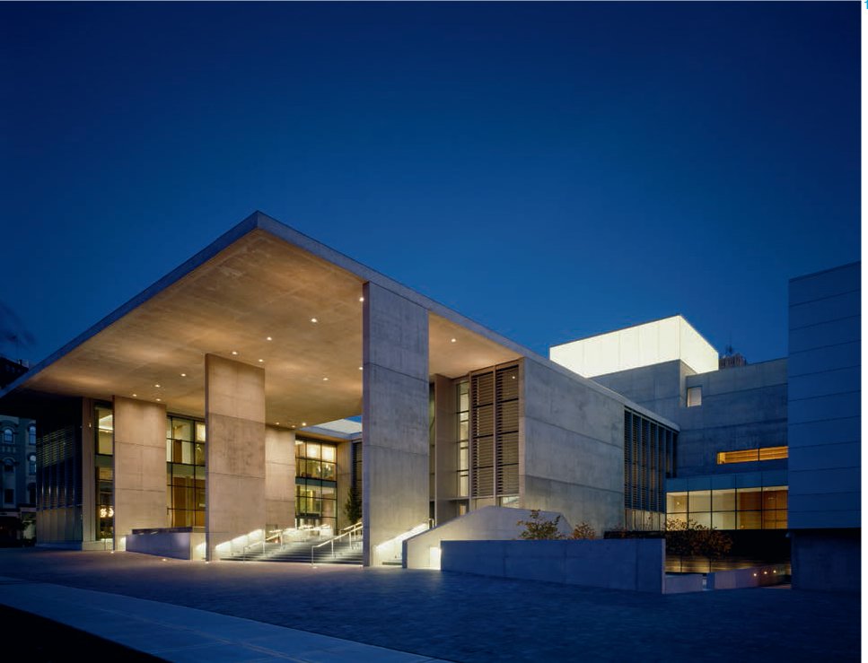
The new Grand Rapids Art Museum occupies a single city block in the centre of Grand Rapids. Its iconic role as a symbol of the city and of civic pride is tempered by the humanistic engagement with art that it affords its visitors.
A large canopy projects out, offering shelter while also capturing views of the city. The entrance facade extends in three sections into the park beyond, seeking to attract and capture visitors into a welcoming embrace. These projecting sections house a museum cafe and other areas with which the public can engage without necessarily visiting the museum’s galleries.
Behind the glass and translucent screens of the facade, the galleries are housed in a three-level tower. At the top of this tower are skylights, which allow filtered natural light to penetrate down into the galleries. At night these skylights become likw beacons, expressing the museum’s cultural activities across the city.
The Grand Rapids Art Museum has as one of its central design philosophies the conservation of energy. Natural light has therefore been used wherever possible throughout the structure. This and other energy conservation strategies have lead to the building obtaining LEED (Leadership in Energy and Environmental Design) certification.
1 At the museum entrance, a massive canopy protrudes into the city. Above, the brightly illuminated tower proclaims the cultural intentions of the building across the night sky.
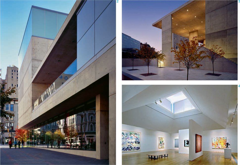
2 At the side, the monumental scale of the museum is broken down to address the urban grain of the surrounding streets.
3 Around the building, social spaces have been designed to encourage interaction and multiple uses.
4 The galleries focus on providing flexible space to display artworks. In all areas extensive use is made of natural light.

Second Floor Plan
1:1000
1 Gallery
2 Lift
3 Stair

15.02
First Floor Plan
1:1000
1 Gallery
2 Library
15.03
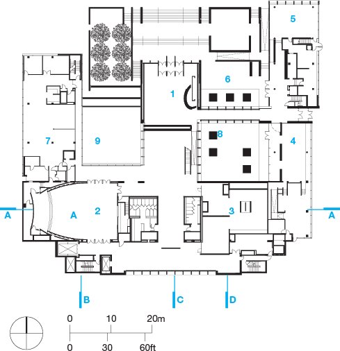
Ground Floor Plan
1:1000
1 Lobby
2 Auditorium
3 Gallery
4 Museum shop
5 Cafe
6 Dining court
7 Offices
8 Sculpture court
9 Reflecting pool

15.04
Lantern Section A–A
1:1000
1 Gallery
2 Auditorium

15.05
Reflecting Pool Section B-B
1:1000
1 Gallery

15.06
Lobby Section C-C
1:1000
1 Gallery
2 Lobby

15.07
Canopy Section D-D
1:1000
1 Gallery
2 Lobby
3 Sculpture court
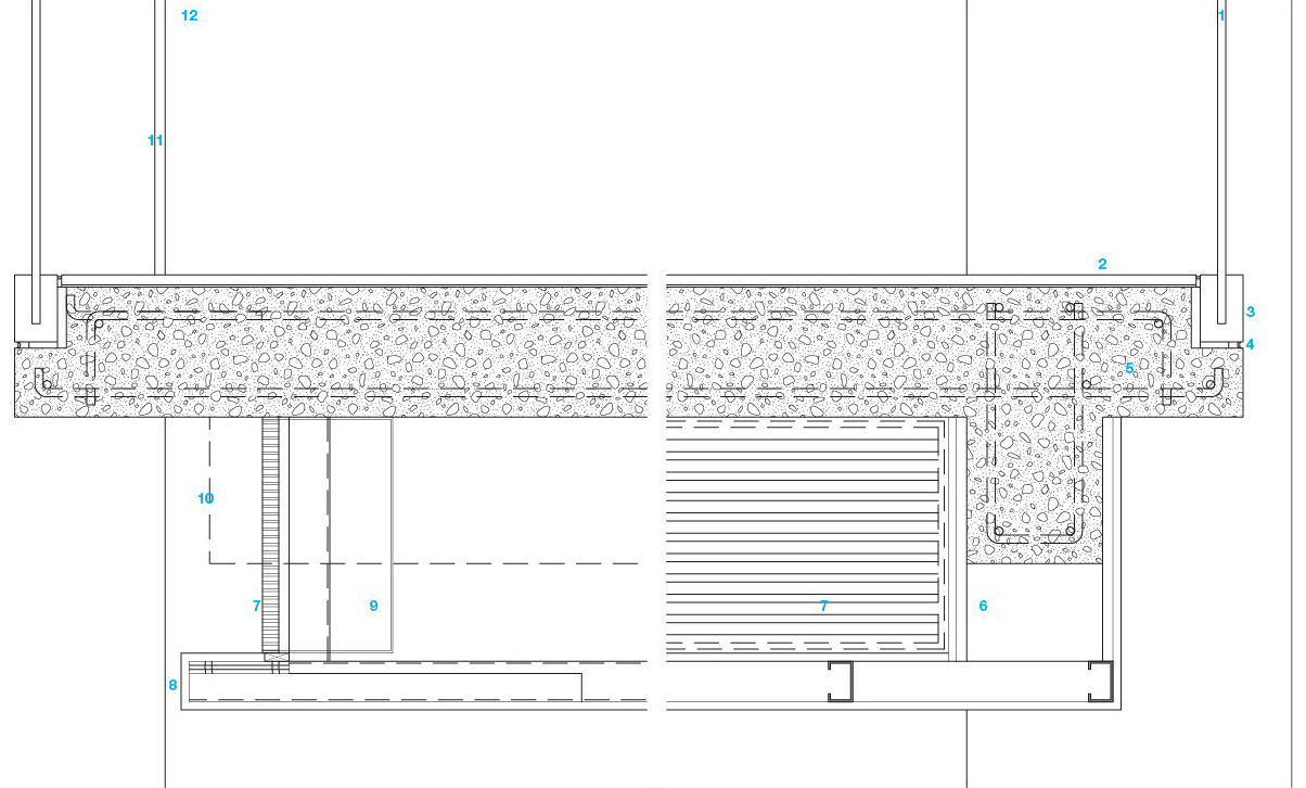
Balcony Detail
1:10
1 13 mm (1/2 inch) tempered glass guard rail
2 10 mm (3/8 inch) wood flooring directly adhered to 203 mm (8 inch) concrete structural floor slab
3 1010 mm (40 inch) wide aluminium guard rail shoe. Clear anodized aluminium brake. Metal cover sheet over
4 Sealant
5 Reinforced concrete slab and beam
6 Return gypsum board c.178 mm (c.7 inch) in at side returns at concrete beam
7 Mechanical grille and frame
8 Firr-out beam with 16 mm (5/8 inch) gypsum board over to align with face of gypsum-board wall finish beyond finish
9 Mechanical duct behind grille
10 Outline of cast-in-place concrete beam at south end of balcony, to align with masonry wall.
11 13 mm ( 1/2 inch) gap for glass and cap rail
12 Face of wall beyond
15.09
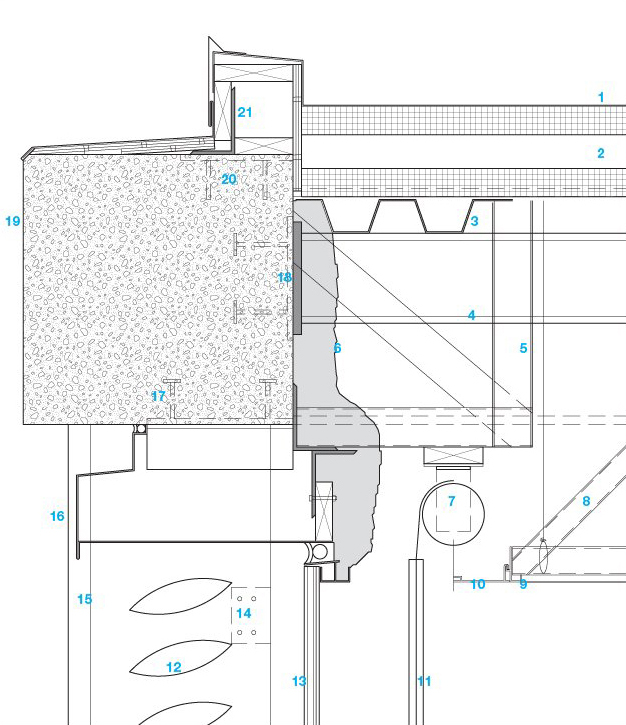
Concrete Roof / Curtain Wall Detail
1:20
1 Single-ply membrane over insulation
2 Two layers of 64 mm (2 1/2 inch) polyisocyanurate, with tapered expanded polystyrene insulations sandwiched between layers
3 76 mm (3 inch) steel roof deck
4 Steel roof beams at column locations with steel plates at ends
5 Framing at 406 mm (16 inch) on centre, bracing at 1220 mm (48 inch) on centre
6 51 mm (2 inch) 2# density polyurethane spray foam, with 25 mm (1 inch) cover coat over for exposed application
7 Motorized sunshade
8 Suspended glass-fibre reinforcedconcrete panel ceiling system. Brace suspension system to structure above
9 Permanent shade pocket edge moulding secured to edge of suspension system
10 127 mm (5 inch) removable closure cover strip
11 152 mm (6 inch) wide prefinished aluminium enclosure over sunshade ends at vertical mullion locations
12 Prefinished aluminium sun shades
13 33 mm (1 5/16 inch) insulated glass in prefinished aluminium curtain wall system
14 Outline of connector between steel tube column and curtain wall mullion
15 406 x 102 x 2840 mm (16 x 4 x 112 inch) steel tube columns secured at bottom of concrete beam above with steel L angles: 102 x 102 x 8080 mm (4 x 4 x 318 inch), one each side of column. L-angles welded to weld plate and to side wall of column
16 3 mm (1/8 inch) prefinished formed aluminium fascia panel. Closure at curtain wall
17 Embedded steel weld plate cast into bottom of concrete beams at centreline of tube column locations
18 Steel plate embedded in back side of concrete fascia beam. Plates located at centreline of roof beams
19 Concrete fascia beam
20 254 mm (10 inch) square embedded steel weld plates at 1200 mm (48 inch) maximum on centre
21 Continuous steel L: 152 x 102 x 8 mm (6 x 4 x 5/16 inch). Welded to weld plates in beam. Holes provided in 152 mm (6 inch) leg at 813 mm (32 inch) on centre for 6 mm ( 1/4 inch) diameter bolts used for blocking attachment
Exterior Concrete Guard Rail Detail
1:20
1 Roof flashing membrane over blocking and extended up aluminium shoe moulding. Concrete pavers on protective pad over flashing
2 Butt glazed aluminium curtain wall mullion
3 Base assembly components of prefinished aluminium curtain wall system
4 610 mm square x 51 mm thick (24 inch square x 2 inch thick) concrete pavers on pedestal system
5 83 x 241 mm (3 1/4 x 9 1/2 inch) recess in top of concrete wall along column
6 Reinforced concrete slab and beams
7 Suspended glass fibre reinforced concrete soffit panel
8 13 mm (1/2 inch) tempered glass guard rail system
9 25 mm (1 inch) insulated spandrel glass in corner panel
10 Prefinished aluminium flashing strip on ‘terrace’ side of rail system
11 105 x 64 mm (4 1/8 x 2 1/2 inch) aluminium shoe moulding screwed down at 305 mm (12 inch) on centre to 114 x 16 mm (4 1/2 x 5/8 inch) galvanized steel plate anchor plate into concrete sill beam with 13 x 105 mm (1/2 x 4 1/8 inch) headed stud at 305 mm (12 inch) on centre
12 Ends of flashing fitted into top inside grooves in vertical legs of alum. shoe moulding
13 Prefinished alum. composite panel system. Prefinished alum. sills above and below, with back frames, trims, etc.

15.11
Concrete Punched Opening Detail
1:10
1 10 mm (5/8 inch) white oak timber veneer
2 10 mm (5/8 inch) fire-treated plywood backer
3 152 x 508 mm (6 x 20 inch) galvanized steel studs at 406 mm (16 inch) on centre. Stud framing secured to 19 mm (3/4 inch) furring system
4 64 x 51mm (2 1/2 x 2 inch) two-component spray foam polyurethane insulation applied to exterior concrete wall
5 38 mm (1 1/2 inch) treated, non-combustible wood blocking, secured to concrete wall and to bottom track of 152 mm (6 inch) stud system
6 Recessed enclosure box for sun shade unit
7 White oak trims, head and jamb
8 6 mm (1/4 inch) reveal created between materials
9 White oak veneer and hardwood trim
10 Reinforced concrete exterior wall
11 Prefinished aluminium sections and mounting
12 Continuous backer rod and sealant
13 33 mm (1 5/16 inch) insulated glass panel in prefinished alum. curtain-wall system

15.12
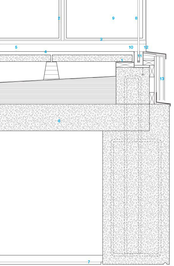
Window Head and Sill Detail
1:20
1 19 mm (3/4 inch) ACX plywood window sill with plastic laminate top surface and back edge
2 38 x 762 mm (1 1/2 x 30 inch) galvanized floor deck
3 203 mm (8 inch) masonry block walls
4 64 mm (2 1/2 inch) spray foam insulation
5 16 mm (5/8 inch) gypsum board over 16 mm (5/8 inch) non-combustible plywood on 92 mm (3 5/8 inch) steel studs at 406 mm (16 inch) on centre
6 Reinforced concrete exterior wall
7 Bentonite water plug strip
8 Layered drainage course strips over back of weep strip
9 Weep strip (CVS010 by Masonry Tech. Inc.)
10 Stainless-steel drip sill
11 105 mm (4 1/8 inch) concrete sill
12 Fluid-applied (or single sheet) waterproofing system with watercourse drainage layer over
13 41 mm (1 5/8 inch) insulated glass in curtain wall framing with four-sided butt glazing
14 Glass fibre reinforced concrete panel soffit
15 Continuous drip reveal