63
Create a 3D Touch Display for the Library
JUAN DENZER / LIBRARY SYSTEMS SPECIALIST
Binghamton University Libraries
Type of Library Best Suited for: Public or Academic
Cost Estimate: $500–$1,000
Makerspace Necessary? Yes
PROJECT DESCRIPTION
Binghamton University Libraries wanted to create an exhibit that would engage patrons through touch, sight, and sound. Their goal was to bring various departments and talents together to make an exciting display. Those involved included faculty from the medieval studies department, the emerging technology studio, student sculpture artists, and library staff.
Illuminated manuscripts were the focused theme of the exhibit. A large 45 × 55-inch printed manuscript image from the J. Paul Getty Museum was the base theme. The display was created using 3D scanning and printing technology. Arduino technology is used to bring touch and sound to the exhibit. In addition to 3D-printed objects, sculptures were made to capture the artist’s interpretation of the printed manuscripts. A custom frame made from a wood and vinyl lattice was built to house the touch print and Arduino technology.
Touch display
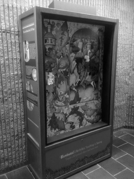
Courtesy of Binghamton University Libraries. Photo by Juan Denzer.
OVERVIEW
This project is designed to give your library step-by-step instructions on how to build an exciting 3D touch display that is 45 × 55 inches. The project can be scaled to fit just about any budget. The 3D touch display will help libraries promote their collections while providing a fun, informative, and interactive exhibit.
MATERIALS LIST
- ◦ Sculpey clay
- ◦ 18–20-gauge stranded electrical wire, 25 feet
- ◦ 18–20-gauge insulated ring terminals, 25+ count
- ◦ Tinfoil
- ◦ Bare Conductive electrically conductive paint, 50 ml (https://www.bareconductive.com/shop/electric-paint-50ml/)
- ◦ Bare Conductive Touch Board (https://www.bareconductive.com/shop/touch-board/)
- ◦ Black interior latex paint, 2 quarts
- ◦ White acrylic paint
- ◦ 45 × 55-inch foam poster board
- ◦ 3M spray adhesive
- ◦ Portable USB Bluetooth mini speaker bar, 4 × 17 × 4 inches or smaller
- ◦ 2-inch-wide Industrial 3M Velcro capable of holding 5 pounds or more
- ◦ #10 ¾-inch wood screws, 25+ count
- ◦ #10 1-inch wood screws, 25+ count
- ◦ 2 ½-inch exterior deck screws, 1 pound
- ◦ 1 inch × 6 inch × 6-foot wood, 2 pieces
- ◦ 1 inch × 6 inch × 4-foot wood, 2 pieces
- ◦ 48-inch × 8-foot vinyl lattice
- ◦ Large-format printed image, 45 × 55 inches
NECESSARY EQUIPMENT
- ◦ Electric miter saw or handsaw with miter box
- ◦ Cordless drill
- ◦ Impact cordless drill (optional)
- ◦ Multipurpose drill bit set
- ◦ Dremel or rotary saw with cutting disks
- ◦ Wire cutter/strippers
- ◦ Wire crimpers
- ◦ Pliers
- ◦ Set of quick grip clamps
- ◦ Laptop or PC with Windows 10
- ◦ iPad or iPad Air
- ◦ 3D printer
- ◦ PLA filament
- ◦ Slicing software
- ◦ Microsoft Kinect (Xbox 360 or Xbox One)
- ◦ Microsoft Kinect for Windows V2 adapter
- ◦ iSense 3D scanner
- ◦ Skanect software
STEP-BY-STEP INSTRUCTIONS
Step 1: Choose an Image
Begin by choosing a theme for your display. Choose something that will help promote a collection. For instance, suppose your library has a new collection of Superhero comic books. You could choose an image that has various superheroes from the Marvel Universe. Choose something that will capture the eye with lots of color. Be sure to choose an image that has multiple objects that stand out and are evenly spaced.
In our superheroes example, we would not choose an image of a single character posing because this would only have one object. Instead, we would select an image that would have several superheroes in an action scene. This might include explosions with cars, buildings, trees, and so on.
It is best to avoid images that are heavily filled with text. Since the goal of the display is to use sight, touch, and sound to interact with the patron, unnecessary text is not suited for it. Any accompanying text can be displayed outside the case, such as having a sign that reads, “For more information, please visit our collection in the children’s department.”
Other examples of images to choose are maps, the solar system, or still life art with fruit. Once you have chosen an image, it will need to be printed using a large-format printer. The display will be approximately 45 × 55 inches in size. You may choose to adjust the size by a few inches depending on the image selected. If a large-format printer is not available or if your budget is limited, a printed poster is an excellent alternative. Note that the standard poster size is 24 × 36 inches; this will make your display smaller than the one in this project. Mount your poster with spray adhesive to the foam board cut to the poster size.
Step 2: Choose and Create Relief Objects Using Clay
The objects that will be scanned should be carefully chosen. They should be key objects in the image that will help to either tell a story or draw the patron into the display. It is also important to avoid the clustering of objects. The display should have touch points that are spaced apart; this will not only help with the touch sensors’ accuracy, but it will also help make the display stand out.
Which objects are best? In our superheroes example, let’s imagine the image included Captain America, Thor, and Ironman. Choosing the entire character as a touch-point object is not a good choice. Instead, choose the iconic objects that the superheroes possess: Captain America’s shield, Thor’s hammer, and Ironman’s helmet. This will help create a more focused narrative when creating the audio file for playback. It also helps to focus on a specific object, so users don’t get confused and think touching a specific area will play additional sounds. Remember that each 3D object will only have one audio file associated with it.
Once the objects are chosen, 3D relief models must be made so they can be scanned in 3D. Use modeling clay such as Sculpey, which can be purchased at any crafts store, to create the models. It is best to start with a flat base and work up to build the relief. If you are not skilled at sculpting, it is better to choose objects that are easily done, such as planets, fruit, hand tools, and so on. The more detailed your object is, the more complex your sculpture will be. The model does not have to be exact, since it is an interpretation of what you are choosing for the display. Do not be too concerned with fine detail, since the scanner and printer might not be able to capture this with precision.
It is important that the models should not exceed the 3D printer’s print bed. Typically, the average size is 5 × 7 inches, so make sure to keep the selected objects to that size. Some objects might call for larger 3D prints. In this case you will have to create sections that will be pieced together.
Step 3: Scan and Print the Molded Objects
If your makerspace is equipped with a 3D scanner, use the scanner to make 3D scans of all the objects. If not, here are some low-cost 3D scan solutions. Each system is designed to achieve suitable scans for this project.
Solution 1: The original Microsoft Kinect for Windows, commonly known as the Xbox 360 version. Used Kinects can be purchased at any gaming store for under $50. This Kinect can be used with a free program called Skanect (http://skanect.occipital.com/). The website has tutorials on how to set up and use Skanect with the Kinect.
Solution 2: The newest Kinect for Windows V2 or the Xbox One version. This will require a PC adapter; both the Kinect and adapter can be purchased for under $150 from the Microsoft store online. Microsoft offers two free Windows 10 apps from the app store 3D Scan and 3D Builder. 3D Scan is designed to work with the Kinect V2. Scanning, editing, and saving 3D scans is easily done. The following link gives a detailed tutorial on how to use it: https://channe19.msdn.com/Blogs/3D-Printing/3D-Builder-Tutorial-Part-5-3D-Scanning-with-Kinect-V2.
Solution 3: Use an Apple iPad. iSense is a 3D scanning adapter that connects to your iPad and can be seen in these videos: http//www.3dsystems.com/shop/support/isense/videos. It allows you to scan objects in 3D and export the files for printing. The cost is around $100. Skanect also offers an iPad scanner for around $499, which includes the pro version of their software.
Once the scans are complete, edit and print them using your 3D printer. If your makerspace is not equipped with a 3D printer, the scans can be printed using online providers such as www.shapeways.com/.
Step 4: Build the Display Frame
Begin by laying out the 1 × 6-inch boards around the printed image. Leave a 1/8-inch gap between the edge of the print and the insides of the board. This will allow for easy removal of the print and make the frame reusable. After making the miter cuts, secure the frame with deck screws to make a portrait frame.
Next, cut the vinyl lattice to cover the back side of the frame. Secure the lattice using 1-inch wood screws. Once the lattice is attached, cut a 4 × 6-inch rectangle in the center of the lattice; this will be the access point for the Arduino board. Paint the entire frame black with interior latex paint. Make sure to include a 1-inch margin around the inside to cover the lattice. If the frame will be mounted on a wall, add three 1 × 4-inch boards to create a brace for the wall and frame.
Once the frame is dry, cut 3-inch strips of Velcro. Cover the corners and a few lattice pieces in the center with these strips. Drill tiny pilot holes in the Velcro and secure them to the lattice with wood screws. With the Velcro in place, carefully lay the print so the non-Velcro sections stick to the print. The end result will be a foam board print with fabric-side Velcro that will stick to the lattice Velcro.
Step 5: Record the Audio Files
The Arduino-based touch board by Bare Conductive (https://www.bareconductive.com/shop/touch-board/) is designed to be used right out of the box. No coding is needed. It includes a micro SD card that is preprogrammed for the project. Use any recording device to create MP3 audio files that will go with each 3D object. The board is capable of 12 touch points. Label the file for each point TRACK00.mp3, TRACK01.mp3, TRACK02.mp3 . . . TRACK11.mp3. Then overwrite the new files to the SD card and insert it into the board. Power the board using a micro USB cable, add a speaker, and test the audio by touching each contact on the board.
Step 6: Paint, Wire, and Secure the 3D Objects
Using the Bare Conductive electric paint, cover the flat side of each object with a thick coat. Take the white acrylic paint and fill in any micro holes on the front of the 3D print.
After the paint is dry, begin to wire and secure the objects onto the print. First place and hold the object on the printed side. Next, drill two to three tiny pilot holes from the back side of the print into the object. Do not drill all the way through the 3D print. Cut lengths of wire that are long enough to reach the holes and the center hole in the lattice. Strip the wire on each end, and attach a ring terminal to one end of each wire. The other ends will be twisted together with one ring terminal to be secured to the Arduino board.
3D print
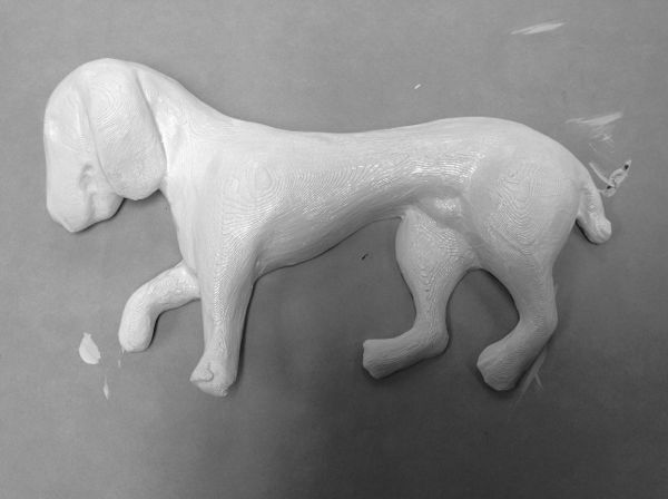
Courtesy of Binghamton University Libraries. Photo by Juan Denzer.
Take #10 wood screws and begin to attach the wires and object to the board. Pass the screw through the ring terminal and add a piece of tinfoil to the screw point. Hold the object on the board and carefully hand screw the ring terminal. It should be on the back side of the foam board and tapped into the 3D object. Do this for all the 3D objects. Once they are all in place, Velcro stick the print to the lattice. Pass all the wire leads through the hole in the lattice and secure them to the corresponding touch point using a wood screw. Secure the Arduino board to the lattice using a few wood screws. Take a micro USB cable, power, and test the display by touching the 3D objects. You will see an amber light when a point is activated. Finally, add the USB powered sound bar to the top of the frame and plug a male-male audio cable from the speaker to the Arduino.
Carefully mount or secure your display to a wall or in a bigger case. Supply power to the speaker and Arduino board, adjust the volume, and enjoy your new interactive 3D touch display.
LEARNING OUTCOMES
Through this project, participants will learn . . .
- ◦ How to select, scan, and print 3D objects
- ◦ Basic electrical wiring for circuits
- ◦ Basic wood framing skills
- ◦ Programming Arduino-based boards
RECOMMENDED NEXT PROJECTS
The case in this project is designed to be highly versatile. Images and objects can be easily swapped out for other themes. The capacitive touch, which is the same technology used in smartphones that enables interaction, can be used with other non-3D-printed objects. This includes items such as fabrics, paper, plastic, wood, and so on. Additional frames can be built in various sizes. Libraries can also use ready-made picture frames to create low-cost interactive displays.
In addition to creating various low-cost exhibits, libraries can invite the community to help make exciting displays. Additional touch boards can be purchased to offer community classes on how to create your own touching-is-seeing display.