Introduction
Freeport-McMoRan Inc. (FCX) owns and operates a copper smelter in Miami, Arizona that treats copper concentrates produced at the North American mine sites. The smelter utilizes ISASMELTTM technology for the smelting furnace , an ELKEM electric slag settling furnace , four Hoboken converters, two anode refining vessels, and a sulfuric acid plant. The smelter typically processes 680,000 dry metric tons (DMT) per year of copper concentrate.
A recent environmental upgrade at the smelter has allowed for an increase in permitted concentrate tonnage. There have been multiple constraints identified in the smelter and acid plant, one of the most significant is the 21 days of down time required to replace the refractory in the ISASMELTTM furnace , during which concentrate cannot be treated.
The refractory life of the ISASMELTTM furnace depends on a number of factors and as a result has varied throughout the life of the furnace . The refractory life was still lower than desired; despite the best efforts of the Miami Smelter staff to improve furnace control and optimize refractory selection. As a result, a project to design and install an intense refractory cooling system to enhance the refractory life of the furnace was initiated.
Project Background

ISASMELTTM Furnace component diagram

ISASMELTTM campaign length
Gradually lowered the furnace operating temperature to reduce thermal stress on the refractory .
Replaced the boiler-tube style splash block with a water-cooled copper splash block; as the old style was a source of leaks that caused downtime.
Performed extensive refractory testing to understand the mechanisms of failure and improve refractory specifications for subsequent brick purchases.
Made extensive improvements in lance control to reduce thermal cycling.
Gradually reduced blast volume down the lance to minimize bath turbulence and erosive brick wear.
Improved overall downstream plant equipment availability to reduce thermal cycling.
Elimination of cooling blocks in the roof with boiler panels, which is outside the scope of this paper
Redesign of the splash block
Replacement of flat billet copper bathline cooling bocks with copper castings
Installation of horizontal plate coolers in the sloped portion of the kettle
Installation of new bathline cooling blocks
Installation of new horizontal plate coolers in previously uncooled regions of the freeboard and the vertical half cylinder upper portion of the furnace
The original boiler tube splash block would last less than one year, due in part to the relatively high gas velocities in the FCX vessel. Large chunks of boiler accretion would also fall onto the block and cause premature failure. A new thick copper block was designed with intensive cooling , copper nickel pipe coils (MTI patent), pockets to retain castable or rammed refractory , and a weld overlay on the ‘nose.’ Installation was problematic as the vessel shell had distorted after installation of the original splash block due to the large horizontal hole in the steel shell. The shell was stiffened as part of the design for the new splash block, and a ‘table’ and trolley installed outside the furnace to slide the block in and out. The current design is expected to last for many years, thereby eliminating a significant maintenance issue.
The original bathline cooling blocks were 4500 mm tall flat copper billets with drilled water passages. Steam was generated intermittently at the top of the water passages due to the poor flow regime with drilled passages. This led to significant vibration and soldered copper joints failing. Several of these blocks were replaced with copper castings with internal pipe coils during an earlier campaign to both eliminate steam generation and the potential for leaking plugs inside the furnace . Internal pipe coils were used in subsequent designs due to their success here.
The flat shape of the bathline blocks did not fit well to the cylindrical steel shell and pattern of the brick. A gap of about 40 mm was present due to the mismatch, which was filled with mortar. As the mortar crushed, pressure on the brick became uneven which led to shorter refractory life. Further, the mortar is a relatively poor thermal conductor, which causes uneven heat removal from the brick, resulting in thermally induced strains in the refractory .
Heat loads are not uniform above the bath, which leads to uneven vertical growth and vertical pressure on the refractory . Such uneven pressure can lead to premature failure of a brick lining. Differential thermal expansion between the tall copper bath cooling blocks and the brick in front of it was the primary cause of premature failure of the refractory just above the coolers. This required a 21-day shutdown to completely reline the furnace .
Traditionally, there were also 10-day mid-campaign outages to reline the offtake area (i.e. kettle) area of the furnace . This was because large accretions would form in the offgas hood and fall onto the refractory in this area thus accelerating the wear.
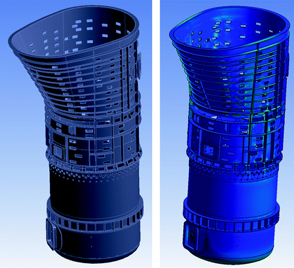
A three-dimensional (3D) model of the furnace shell, refractory , and cooling blocks (copper , pipes, thermowells) was developed for the preparation of all design drawings, analysis, and extraction of quantities.
The copper plate coolers utilized a ‘tulip’ shaped groove on the hot face to retain refractory . The grooves had radii to reduce stress concentrations associated with sharp edges in the refractory .
The number of shapes was minimized with a novel pattern to accommodate the complex shape of the slope profile in the kettle.
Hold backs were added on the copper tabs which extended through the shell to prevent any block from falling into the furnace either during operation or maintenance . Installation, operation, and maintenance all need to be included in the design of any furnace component.
Openings were cut in the steel shell as the furnace was bricked to accommodate the copper tabs with the inlet and outlet piping and thermowell.
The shell was stiffened on the outside due to the considerable number of holes. A check of the shell stresses was performed using finite element analysis (FEA).
A thermal analysis was performed on the cooled portion of the kettle; including the shell, refractory , and cooling blocks. Performance curves were developed for each cooler to establish appropriate thermocouple alarm limits.

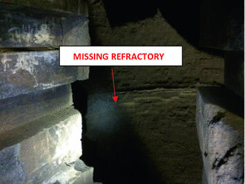
Missing refractory on bath zone copper cooler
Even though the cooled kettle area refractory was in good condition, it had to be removed three times during subsequent relines of the furnace as it created an overhead hazard when replacing brick below. This increased the reline time and lost production. Based on the measurements taken from the cooled kettle area refractory after 9-month campaigns, a 3-year campaign life appeared achievable if the intensive water cooling was expanded to the entire vessel. The design goals were to make the furnace cooling system modular to facilitate partial refractory replacement, eliminate the bath zone refractory failures, and incorporate heat loss/wear monitoring by zone.
The timing of the proposed refractory cooling project was such that it would coincide with a scheduled 24-day outage for a heat exchanger replacement at the sulfuric acid plant. After an extensive investigation of the timeline with the refractory installation contractor, MTI, and copper cooler manufacturers, it was determined that the cooling system could be designed, procured, and installed by the end of the planned outage.
Utilizing the existing furnace shell and bath zone cooling water connections
Incorporating an existing heat exchanger that wasn’t in service
Utilizing existing main cooling water manifolds to supply the new cooling system via smaller manifolds for each zone
Optimizing shell stiffening steel additions
Miscellaneous piping fabrication/installation prior to the outage
Optimizing cooler design for minimal shell cutting
Design of 2017 Cooling System Upgrade
The furnace at FCX posed several technical challenges to the design. It was also necessary to minimize both capital costs and shutdown duration.
Premature failure of brick at the top of the bathline cooling blocks, as it was a significant cause of short campaign life.
Rapid wear of brick in front of the bathline coolers.
Refractory wear above the bathline coolers, except for the sloped portion of the kettle where the recently designed system was performing very well.
Uneven pressure on the brick due to uneven vertical expansion and constraint from above.
Replace the flat vertical cooling blocks in the bathline with curved panels, to make heat removal from the brick uniform, and reduce stresses due to uneven radial grown between the brick and the cooler . The thick layer of mortar with the faceted flat panel layout was thus eliminated.
Retain the design for the splash block, including the system of mechanical fastening to the shell and expansion allowance.
Develop a pattern for plate coolers above the bathline based on expected heat loads and proven MTI designs used elsewhere.
Retain the recently installed horizontal plate coolers in the kettle and employ this pattern as the basis for the remainder of the upper portion of the vessel.
Employ a pocket pattern where possible to hold protective accretions; based on the successful performance on the splash block.
Install a minimum of dual cooling circuits in high wear areas.
Use existing openings in the steel shell wherever possible.
The design of an individual cooling block to remove the required heat load is a relatively straight forward task. Well established existing designs could be relied upon for most of the detailed design. However, the nagging issue of vertical expansion remained, both at the top of the bathline and for the remainder of the furnace .
A novel design approach with lintel coolers was adopted (MTI patent pending) to partition the furnace into three zones: the bath line, freeboard, and upper barrel/kettle. Each zone is supported independently to balance vertical expansion and pressure on the brick. Brick, cooling blocks and accretions within a zone can be supported by a lintel ring below with a backup steel shelf in close proximity to the lintel for redundancy. Brick in front of the bathline coolers are still supported by refractory below. The lintel ring design mates to the splash block, so that the same amount of expansion allowance material could be used below and above the ring. Further, the lower lintel ring is designed to accommodate the step change from the bathline coolers to the plate coolers.
The lintels and bathline coolers were designed to withstand high heat loads in case of refractory loss at the top of the bathline coolers.
The existing shell was retained to minimize the time for the shutdown. New holes needed to be cut for the additional plate coolers and lintels. A sizeable number of stiffeners were added to compensate for the new shell cutouts and as well as the need to carry forces from the lintel rings.
Refractory drawings were updated to reflect the changes in required expansion allowance within each ring of brick.

Model of Modified ISASMELTTM furnace with surrounding building Steel

3D model and shell stress analysis

Sample thermal analysis for part of the freeboard area
Installation
The project engineering was completed in phases to deliver items that could be fabricated or procured in advance of the actual outage. The cooling elements had the longest lead time and as a result took precedence; followed by piping, structural steel modifications, and lastly, instrumentation.

Plate cooler supply and return manifold assemblies
The piping for the plate cooler manifolds included temperature , pressure, and flow measurements with a bypass that would allow them to be serviced without shutting down the furnace . Each individual circuit services 8–11 plate coolers in series. These circuits include manual globe valves, flow indication, ball valves, drains, pressure indication, temperature indication, and a pressure relief valve. This allows for flow adjustment and pressure leak testing for individual circuits.

Bath zone cooler supply and return manifolds and circuits

Bath line cooler installation
Installing the plate coolers required measuring out the location inside the shell and cutting out the hole. This was done with one course of brick early so the bottom of the hole could be cut to have the required clearance for any expansion and contraction of the refractory during operation. The plate cooler was laid into the hole with the overhead crane after the next brick course was laid and a safety holdback was bolted to the cooler externally.

Plate cooler and inspection door installation
The shell stiffening steel was a point of complication as it was known that the furnace shell had been distorted over its life; however, there was no reasonable method to quantify it. All of the stiffening steel design and fabrication was based on a straight furnace shell so there was a fair amount of trimming anticipated prior to the outage. The stiffening steel could not be installed prior to the outage even though it was procured. Some of the steel was in close proximity to coolers protruding through the shell. Their exact positions could fluctuate as governed by refractory course work. Coordinating the cooler , stiffening steel , and flex hose installations in that order was a challenge.

Stiffening steel installation and fabrication

Plate cooler circuit piping runs and hose connections
The final aspect of the project was installing and connecting any remaining instrumentation to the new remote I/O racks and junction boxes built prior to the outage. This was done last because the hot work and congestion in the area would have damaged the wiring and instruments. The instrumentation is only intended to monitor the system so the furnace heat up could begin without it, as long as water flow was confirmed through all circuits. In addition to the cooling water instrumentation mentioned previously, every plate and bath cooler had a dedicated thermocouple with alarm set points based on the FEA results to prevent damage to the coolers.
Operation

Cooling system zones

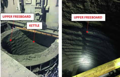
Upper freeboard and kettle condition

Freeboard condition

Freeboard heat loss variation during operation

Cooling system conditions during low (left) and high (right) heat losses

Bath block cooling heat loss comparison for new cooler design
Summary
The FCX Miami Smelter and MTI designed and installed an intense refractory cooling system in the ISASMELTTM primary smelting furnace . The intent of this cooling system was to prolong the refractory life of the furnace , which was the cause of frequent outages and lost production. The design was fashioned after the previously successful refractory cooling system in the ‘kettle’ area of the furnace .
The cooling system has been in operation for 9.5 months and has operated without any significant issues or cooler leaks. An inspection was conducted during an outage in November 2017 and the refractory and cooling system was found in good physical condition. The refractory in the plate cooler zones (kettle, upper freeboard, and freeboard) showed wear ranging from 25 to 100 mm. The bath zone refractory had some wear in the previous failure area at the top of the coolers, but the remaining refractory was in good condition and likely thicker than at the same time into the previous campaign as shown by Fig. 18.
The main factor to lower heat losses and wear rates is good operational control that establishes a stable slag coating. There has been no indication that higher concentrate throughput increases heat losses as long as temperature is held constant.
Based on the observations during the inspection and the FEA data, the plate cooler areas should find an equilibrium wear point and drastically slow down to provide a long refractory campaign. The bath zone refractory will likely wear back to the coolers later in the campaign. The bath zone coolers are designed for large heat loads and should be able to establish a slag coating and continue safe operation.
Acknowledgements
The authors would like to thank the FCX Miami management team, as well as Western Refractory Construction Inc. and FCX Miami Maintenance for installing the cooling system components. We would also like to thank the FCX Miami Instrumentation and Process Control groups for building and installing all associated electrical equipment, as well as making the final instrument connections. Lastly, thanks to Robert Brandt and Patrick Essay of the FCX Miami Smelter Metallurgy Department for their project management assistance.