This chapter looks at the interior of the Stage 2 models, and covers the dashboard, instruments and controls, the seats, the interior trim, and the tools supplied with the vehicle.
There were essentially two levels of interior specification for the Stage 2 models: a basic level intended for the utility models and fleet-specification Station Wagons, and a more luxurious one for the County Station Wagons. There were also several cosmetic changes over the years.
DASHBOARD
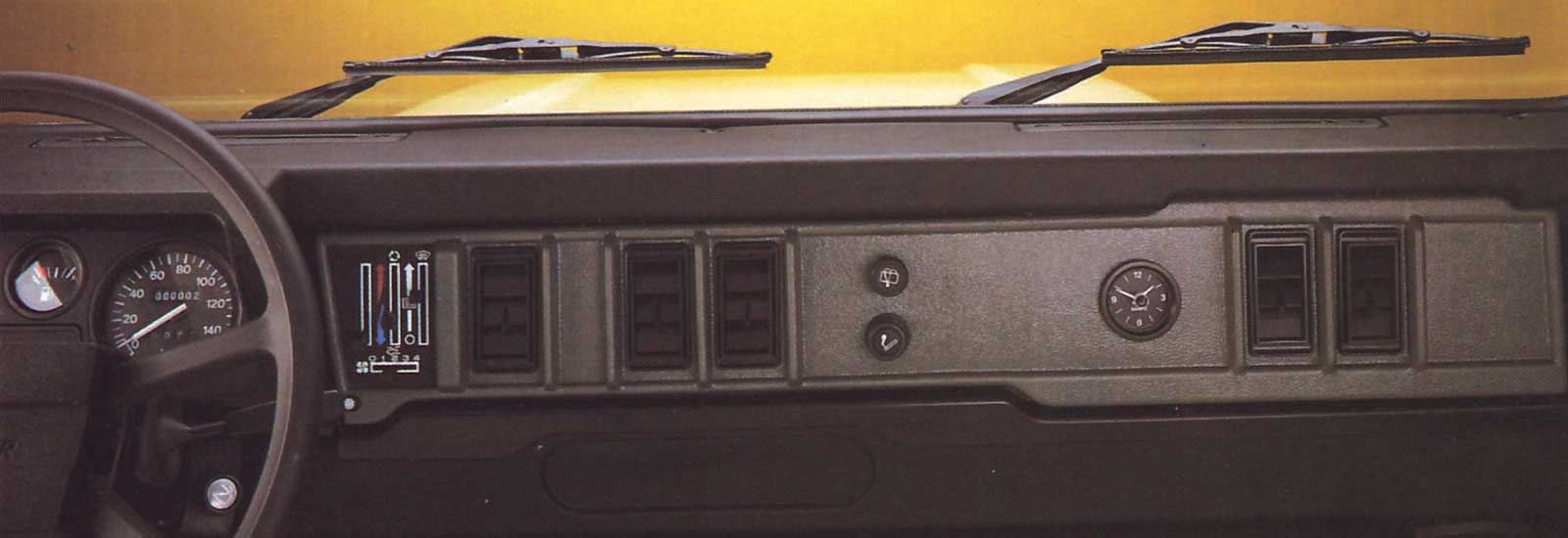
All the visible elements of the Ninety and One Ten dashboard were made of plastic, with a black facia rail, the main instrument panel ahead of the driver, and a black plastic lower rail. In between was an angled panel in grey plastic with two rows of vent slats in the centre, and with a cylindrical element to the passenger’s side of the centre, which took hot air up to the two windscreen demister vents in the top rail. Outboard of each set of ventilator slats was a lever that opened and closed the ventilator panels at the base of the windscreen.

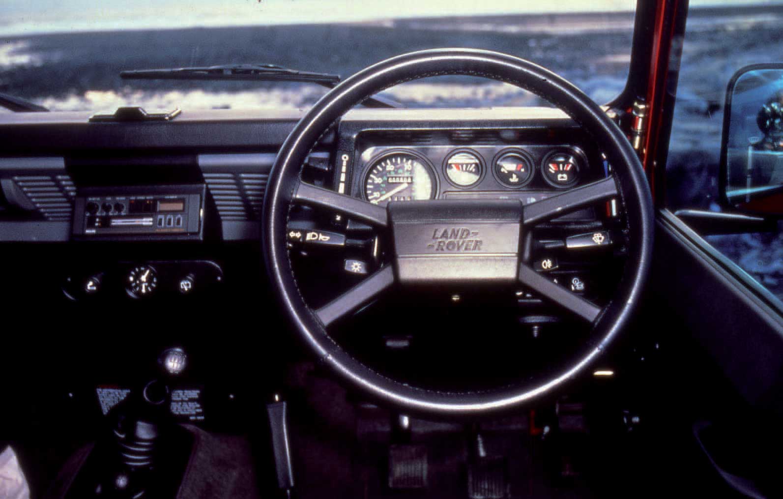
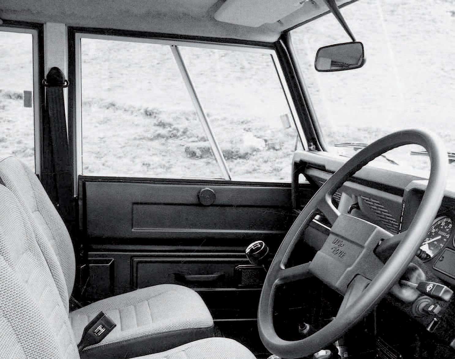
The dashboard of a 1983 4-cylinder County Station Wagon showing the instrument panel layout, the early type of steering-wheel hub, and the position of the clock. The optional ash tray is just visible under the centre of the dash, and the fire extinguisher in the footwell was another option. The gear levers and handbrake are also clear here.
There was a stowage section for small parcels in the centre of the lower facia rail, and a second one ahead of the passenger. There was an adjustable footwell vent under the bottom rail on the passenger’s side, but no equivalent for the driver. On the passenger’s side, the dashboard terminated in a vertical grab handle between top and bottom rails.
The centre of the bottom rail was recessed to accommodate small instruments, although none were standard initially except on the County Station Wagon, where there was a quartz analogue clock in the centre. This clock remained standard on County Station Wagons, but was always an optional extra on other models.
Additional controls could be fitted in the central panel next to the clock. A cigarette lighter became standard on all 1985 models and was fitted on the driver’s side of the panel, outboard of the clock (or the clock’s position). On models with a rear wash/wipe system, the control for this was fitted into the panel on the opposite side of the clock. There was an additional small control panel on the lower dashboard rail, outboard of the steering wheel. This contained three switch positions, of which just two were normally used. The central position was occupied by the hazard warning lights switch (when fitted), and the outboard one by a switch controlling the panel and interior lights. In May 1985, at VIN 233401, the hazard lights switch was modified with beryllium copper flexing contact material instead of phosphor bronze, which was prone to distortion.
The steering-wheel hub was changed for the 1987 model-year, and a new central mounting was introduced for the radio. This is a 1988-model County, with leather-bound steering-wheel rim.
Below the centre of the dashboard was a detachable black cover panel for the fusebox. (For details of the fuses, see Chapter 6.) This cover panel had a decal on the outside that provided operating details for the transmission. On the 1987 and later models, a bonnet release grip was located under the right-hand side of the facia (on earlier models the bonnet was released from the grille panel).
On early models, an ash tray below the dash was an optional extra (see Chapter 8). Then from some time in 1985 – either early in the year or during the summer – an ash tray with a hinged lid was fitted as standard into the centre of the dashboard top rail.
Air Conditioning
A fully integrated air-conditioning system made by ARA was optional from the start of production, and it came with a special version of the dashboard. A flat front panel with a grained finish covered the whole of the open stowage area on non-air-conditioned models. There was a control panel with vertical sliders just inboard of the instrument panel, and the refrigerated air was expelled through five louvred vents set into the main dashboard cover panel. The clock, if fitted, was mounted in that panel, just inboard of the two outer vents and in front of the passenger. When a cigarette lighter and wash/wipe control were fitted, they were mounted just inboard of the third (central) vent. They were arranged vertically, with the wash/wipe control above the cigarette lighter.

The cigarette lighter and the rear wash-wipe control were typically located alongside the clock when these items were fitted. This is a 1988 County model, with the DC550 radio-cassette then fitted to UK models.
INSTRUMENTS AND MINOR CONTROLS
Instrument Panel
The instrument panel was always made of black plastic, and there were different versions to suit RHD and LHD models. The speedometer was the largest of the dials and always mounted on the inboard side of the panel. Both miles-per-hour and kilometres-per-hour types were available, to suit the destination market. All speedometers had an overall mileage recorder, and a speedometer with a trip recorder was available as an option; this had a reset button at the six o’clock position of the speedometer face. There were then three smaller dials at the top of the panel, above a panel of warning lights.
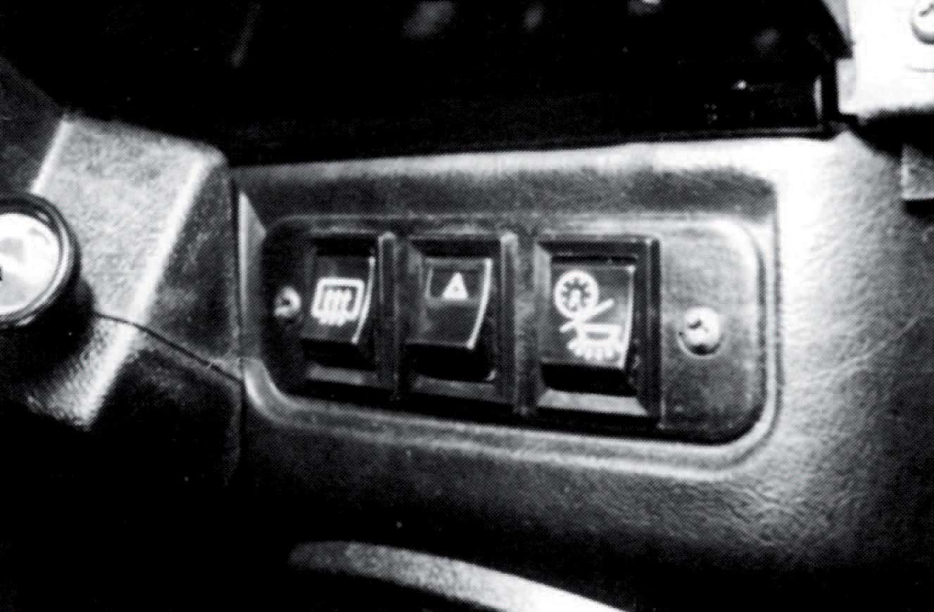
Minor controls were located in a panel outboard of the steering wheel. This one is on a RHD vehicle.
There was an additional air vent on the outer edge of the air-conditioning dashboard. The arrangement of the instruments on LHD models was a mirror image of the RHD layout.
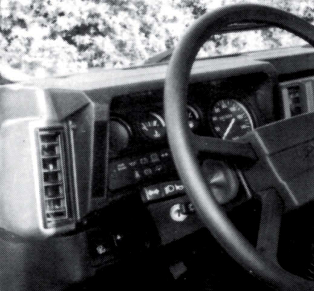
Pictured here on a LHD model is the dashboard used on air-conditioned models. The control panel for the heating and air conditioning is beside the instrument panel, and the choke control on the steering column is also visible here.
The three smaller dials consisted of a fuel gauge, temperature gauge, and battery condition indicator. The fuel gauge was always next to the speedometer, and the temperature gauge in the middle of the three. The bezels of these dials were always black, like that of the speedometer.
There were eighteen segments in the warning light panel, but not all were used for all vehicles; some were associated with options, and others with special features for export markets. When not needed, warning lights were simply not connected and were not fitted with bulbs. The lights were as follows:
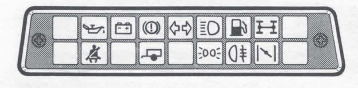
The warning light panel was located below the three smaller dials on the instrument panel, and is most easily illustrated with this drawing.
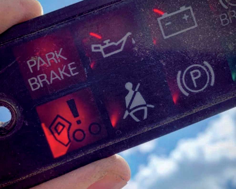
The redundant warning light for the tilt cab of the planned Llama model is seen here. This example was originally fitted to a 1991 Defender model. GREG KING
From 1987 there were changes to this warning light panel. The changes of lights are noted in the table on the previous page, but one deserves extra comment. This is the special light in the first (extreme left) position on the bottom row, which was never fitted with a bulb on production.
As Chapter 1 explains, in the mid-1980s Land Rover planned to produce a forward-control variant of the One Ten (known as Project Llama) with a cab that tilted forwards to give access to the engine. This model was to share its warning light panel with the One Ten, and the panel was modified appropriately. A new warning light was added to guard against the vehicle being driven with the cab not fully locked into its standard position, and this light was illustrated with a symbol showing the cab tilted forward. The Llama did not go into production, but it was too late to change the new warning light panels, so these were used up on Ninety and One Ten production, the actual light of course not being connected. These panels were still being used by the time of Defender production (1991 model-year, HA suffix).
Heater Controls
Controls for the air-blending heater were mounted alongside each end of the instrument panel. There were vertical sliders to control the temperature and air distribution (that is, to the screen or the footwells) on the outboard side, and another vertical slider for the blower fan on the inboard side.
The early heater-control cables could prove stiff to use, and from December 1985 they were re-routed and were pre-lubricated before assembly to give smoother operation.
Steering Wheel and Column
The steering wheel was always a four-spoke type, based on that used in Range Rovers between 1979 and 1986, and made of black polypropylene; the Range Rover wheel was grey. The central crash pad had the Land Rover zig-zag logo moulded into a central recess, and the rim was in plain plastic without any covering. Early steering wheels were sometimes misaligned, and improved production controls were introduced at VIN 251042 in February 1986 to overcome this.
From the 1988 model-year, a new style of centre finisher was fitted, still with the Land Rover zig-zag logo but now with two ‘tramlines’ to frame it instead of a recess. There was a special version of this wheel for County Station Wagons, with black leather trim around the rim.
The steering column had a grained plastic shroud, with a stalk switch and a smaller switch on each side. On the left side, the stalk switch controlled the direction indicators, horn, main beam and headlamp flasher, and the smaller switch was for the main lights. On the right side, the stalk was for the windscreen washers and wipers, while the smaller switch was for the rear fog guard lamps. These positions were for right-hand-drive models; on those with left-hand drive, the smaller switches swapped sides but the stalks remained unchanged.
The shape of the gaiter for the wiper stalk was changed slightly in August 1984 at VIN 213973 to give better clearance on the underside of the steering-wheel spoke. The headlamp stalk was modified in December 1984 at VIN 225943, with improved Lucar connectors to give a more positive harness location.
The keylock for the starter was always on the left-hand side of the steering column (inboard for RHD, outboard for LHD). On diesel models, the starter key also engaged the glow-plugs when necessary. A mechanical steering-column lock was optional on early models, and became standard from the start of the 1985 model-year.
From VIN 415403 in approximately November 1989, a new ignition switch was made standard on petrol models. This was designed to prevent the starter engaging the ring gear (with accompanying sounds of mechanical distress) while the engine was in ‘backrock’ after an unsuccessful attempt to start. The new switch required the key to be turned to the ‘off’ position before a second attempt could be made to start the engine. Land Rover also introduced a Service modification for earlier types; this involved fitting an electronic inhibitor into the existing starter circuit, so introducing a two-second delay before the starter would fire for a renewed attempt at starting the engine.
The choke control (on petrol models) was always mounted on the right-hand side of the column shroud, irrespective of LHD or RHD. At VIN 325751 in approximately February 1988, increased tinning of the engine end of the inner choke cable was introduced to improve reliability.
Keys and Locks
These Land Rovers were normally supplied with two sets of keys. Each set contained two keys, one for the ignition and the other for the doors and bonnet. From VIN 218241 in approximately June 1984, the spare set of keys was supplied on a plastic strap attached to the radiator support bracket on the right-hand side of the vehicle – although it is highly unlikely that any sets are still there now!
Additional locks were available for the fuel filler and for the centre cubby box. To avoid the need for too many keys, Land Rover rationalized the system in the mid-1980s so that each vehicle was still supplied with only two keys as standard. One key was for the ignition and the other covered all other functions – doors, fuel filler, and centre cubby when fitted.
Radio
Early models had no preparation for radio, but from the start of the 1985 model-year, County Station Wagons came with a radio preparation kit. This consisted of a power supply lead, two speakers with leads, and an aerial, although the radio itself still cost extra. The aerial lead lay coiled under the wing if not connected to a radio. The radio itself was typically fitted in one of two positions: one was on the underside of the parcel shelf on the passenger side between the fusebox cover and the footwell vent; the alternative position, suitable only for vehicles fitted with a centre cubby box, involved cutting away the ‘floor’ of the trinket tray in the cubby box and mounting the radio vertically inside the front of the box.
A dedicated radio mounting panel was made available on 1987 models, becoming standard on County models (which now had a radio as standard) and an option for others. It was added to the centre of the dashboard above the clock.
The radio fitted to County models in Britain was in fact a combined radio-cassette unit, a Philips DC550 with FM, MW and LW receptions, plus sixteen pre-set stations (eight for FM and four each for MW and LW).
There is more detail on radios, speakers and aerials in Chapter 8.
DRIVING CONTROLS
The steering wheel has been covered above, in the section on the dashboard.
Pedals
Brake, clutch and accelerator pedals were all pendant types with replaceable rubber pads. The ribbing on the brake and clutch pedal pads runs from left to right; that on the smaller accelerator pad runs vertically.
From VINs 267092 (Ninety) and 267365 (One Ten) in approximately August 1986, an improved accelerator cable was fitted, and on RHD models it was re-routed on the opposite side of the pedal box. From VIN 296250 in approximately May 1987 there was a completely new accelerator cable for the 4-cylinder petrol models.
Main Gear Lever
There were different main gear levers to suit the different gearboxes fitted.
The LT77 five-speed gearbox in 4-cylinder models came with a straight gear lever, and the ball-type gear-shift grip was marked in white with the five-speed gate. The bellows-type gaiter was made of black rubber, and was part of a larger moulding that also provided a gaiter for the transfer-box lever. There were some problems with the security of the gear lever on early models, and at VIN 233995 in approximately February 1985 the yoke bolt securing the gear-lever yoke to the selector rail was treated with Loctite to prevent it working loose in service. Then at VIN 238945 in approximately May 1985, a new lower gear lever was fitted, with solid pin rather than roll pin fixings. Again, the change was made to cure looseness in service.
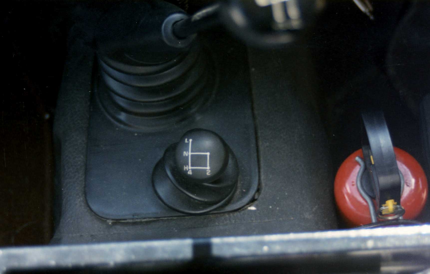
Another rarity was this version of the transfer-box lever, only used on early One Tens with selectable four-wheel drive. PETER HOBSON
The LT85 five-speed gearbox had a cranked gear lever, with a rubber bellows-type gaiter that covered only the base of this main lever. The shift grip had a flatter top than the LT77 type, with the five-speed gate marked on it in white.
The LT95 (and LT95A) four-speed gearbox had a cranked gear lever, with a flat-topped grip that showed the positions of the four-speed gate in white. The gaiter for this covered only the base of the main gear lever; the transfer-box lever was mounted on the heelboard of the seat box.
Transfer Lever
With the five-speed LT77 and LT85 gearboxes, the transfer-box selector lever was to the rear of the main gear lever, and was marked with six positions: on the left, the grip was marked ‘diff lock’ (because the differential lock was automatically engaged with low range), and on the right the positions were marked L-N-H (for low, neutral and high). On the rare 4-cylinder models with selectable four-wheel drive, the grip was marked L-N-H and 4 on the left, and N-H with a 2 on the right. (When the optional freewheeling front hubs were fitted, there was also a red instruction label on the dashboard; see Chapter 8.)
With the four-speed LT95 gearbox, the transfer box lever was mounted in the heelboard below the driver’s seat. The grip was marked L-N-H.
Differential Lock
The differential lock on models with the LT230 transfer box was controlled by the transfer-box lever (see above). However, there was a separate differential lock control on vehicles with the LT95 four-speed gearbox. This was mounted on the heelboard and operated the differential lock through a vacuum system; pulling the knob out engaged the differential lock, and pushing it in disengaged it.
Handbrake
The handbrake lever on all models was mounted to the floor on the driver’s side of the transmission tunnel. The shaped grip was in black plastic, and the release button at the end was white plastic. There was a rubber bellows-type gaiter.
In February 1986, at VIN 251575, a ‘P’ clip was added to the seat base on LHD models to secure the handbrake cable and prevent it from rattling.
SEATS AND UPHOLSTERY
Most utility models of the Ninety and One Ten came with three seats in the cab area. The Ninety Station Wagons and County Station Wagons had seven seats, made up of three in the cab area and four individual inward-facing seats in the load bay. The One Ten Station Wagons and County Station Wagons came with a ten-seat configuration outside the UK, but to avoid Purchase Tax in the UK they had a twelve-seat configuration. Both types had three individual front seats and a forward-facing ‘second row’ rear bench for three passengers. The ten-seaters had four individual inward-facing seats in the load bay, but the twelve-seaters had two inward-facing three-seater benches.
Seats in the Cab
There were three different types of seat in the cab. These were the basic (utility) type, the DeLuxe type (for standard Station Wagons and as an option on other utility models), and the County type (primarily for County Station Wagons but also available as an option).
Basic
The basic cab seats had no adjustment and flat cushions, and their lower cushions were removable to give access to the lockers in the seat box below. They were upholstered in plain black vinyl. Land Rover sometimes described these as ‘fleet only’ seats (that is, for fleet buyers), and they were withdrawn from the UK market at the start of the 1989 model-year.
De Luxe
The De Luxe seats came with fore and aft adjustment for the outer two seats only, and had some contouring at the sides. They were upholstered in pleated black vinyl. The centre seat was always fixed in place.
County
The original County seats were derived from those for the Leyland T45 truck, and were styled and contoured for support. The two outer seats had three-way adjustment, the backrest rake being adjustable manually and then locked by means of a lever on the outboard edge of the cushion. On County Station Wagons, the transverse grab rail fitted behind the front seats on standard Station Wagons was omitted, to permit backrest adjustment. Cushion height could be adjusted by removing the cushion and repositioning a spring-loaded bar. Matching headrests were available for the two outer seats. The original County seats were upholstered in foam-backed tweed cloth with a dot pattern, and had leathercloth sides.
County seats were available as an option for all One Tens except Truck Cabs (where there was not enough room), and on standard Station Wagons it was theoretically possible to order County front seats with standard vinyl seats behind – although this option was probably very rarely taken up.

Early County Station Wagon seats were upholstered in brown tweed. Head restraints were standard on the outer front pair.
From July 1987, County vinyl seats became standard on non-County models, which in effect meant the standard seats now enjoyed the same range of adjustment as the earlier County type. These were accompanied by head restraints on the outer pair, except on pick-ups.
There were some running modifications on assembly, in addition to the changes of upholstery recorded in the table below. At VIN 266922 in approximately July 1986, a stronger and more durable wooden support was supplied for the base of the seat cushion, giving better location on the seat base as well. Then in December 1988, for the 1989 model-year, the squab of the County front seats was modified to enable it to move 25mm further back.
From the start of production, the centre seat in the cab could be replaced by a lockable cubby box as an option. There are more details of this in Chapter 8.
Seats in the Rear
The standard rear seat on both Station Wagon and County Station Wagon models of the One Ten was initially a fixed three-seater bench. For the 1987-model One Ten ten-seat Station Wagon, this bench was replaced by a new asymmetrically split contoured seat. The four inward-facing rear seats were then repositioned to give more shoulder room in December 1988 for the 1989 model-year. Note, though, that neither of these changes affected the twelve-seat Station Wagons that were sold in the UK.

The arrangement of the rear folding seats in an early Ninety County Station Wagon.
Ninety Station Wagons came as standard with a fixed inward-facing bench seat for two on each side of the load area. On the Ninety County Station Wagons, these benches were replaced by four individual seats with cushions that could be folded up to increase the load area. Each seat had a retaining strap to hold the folded cushion in position.
UPHOLSTERY
There were several changes to the upholstery over the years, and the easiest way of understanding them is from a table.

When early County seats were specified as an option, they came in grey tweed.

All-grey interior trim became standard on 1988 models. This is a Ninety County Station Wagon, with the second type of cubby box. It also has air conditioning.
Although County-specification cab seats (contoured, and with headrests on the outer pair) were available as an option, the optional versions came with grey tweed cloth (with a black and white fleck) and grey vinyl side panels. The brown ones were reserved strictly for the County Station Wagons. This option was discontinued at the end of the 1987 model-year.
The standard grey seats on 1988– 1989 models had the same dark grey colour as the door trims, and the vinyl upholstery had welded seams to improve durability. The cloth seats were in grey with grey vinyl backs and borders.
SAFETY BELTS
All models were provided with safety-belt mountings as standard, but the legal requirement for belts differed from one country to another. What was standard in some countries may therefore have been an extra-cost option in others.

The 1987 models had mini-reel inertia belts, which gave a tidier appearance and a little more foot room in the rear.
Notes:
County brown tweed cloth was also known as Brushwood/Berber cloth.
When belts were fitted to the front seats, they were inertia-reel types for the two outboard seats, but a static lap-strap only for the centre seat. The inertia reels themselves were mounted in different ways on different models. They could be mounted behind the seat to its base; on truck cab models they were mounted to a reinforcing rail at the bottom of the cab base; and on models with a full-length hood they were attached to the transom panel at the front of the body tub. From autumn 1986 for the 1987 model-year, new mini-reel inertia belts were fitted for the front outboard seats.
Second-row belts in Station Wagons and County Station Wagons were static lap and diagonal types on the two outboard seats, with a static lap strap for the centre seat. There were ‘keeps’ on the door pillars for the buckles of the belts on the outboard seats. For the 1987 model-year, the new mini-reel inertia belts were made available as an option for the two outboard seats.
It appears that early One Ten Crew Cab models could not be fitted with belts for the rear seat, as the anchorages had been designed and tested but not certificated by the British Department of Transport by November 1987.
The four inward-facing rear seats came with static lap straps only. No belts were available for the bench-type inward-facing seats in UK-market twelve-seat Station Wagons and County Station Wagons.
BODY TRIM
Door Cards
Land Rover referred to ‘trimmed’ and ‘untrimmed’ models, the untrimmed ones having bare metal inside the doors and no door cards. Station Wagons always had door cards, and these were optional on other models.
Early One Ten door trims were foam-backed with moulded black plastic facings. The grab handle and door-release lever were mounted quite low down, there was a document pocket, and there were separate cover panels for the door check strap and the lock.
New door cards were introduced on 1985 model-year vehicles, and were therefore fitted to all ‘trimmed’ production versions of the Ninety. The casings were restyled, and the grab handle and door release were mounted higher up. These door trims now incorporated sill locking buttons for the first time on a Land Rover. On County models, an ICE speaker with a plastic faceplate was mounted at the lower front section of each front trim.

The early door trim is seen here on a 4-cylinder One Ten County Station Wagon.
There were further revisions to the door casings for the 1987 model-year, and then for the 1988 and 1989 model-years the trim colour was changed to dark grey. The existing black door furniture – for the winder, grab handle, lock button and door release – was retained unchanged.
Station Wagons of all types had a simpler tail door-trim panel, with a tubular metal grab handle and a cover for the lock. This changed to dark grey for the 1988 model-year, along with the other trim in the vehicle. Tail doors on hardtop models were not normally trimmed.
Door Locks
All door locks were manufactured by Kiekert, and all were manually operated (central door locking would not reach the utility Land Rovers until the 2002-model Defender).
Two types of door lock were used over the years. Early models had a direct lock, similar to the type used on the Series III models. In this case, the lock assembly was exposed on the inside of the door and had an integral operating handle. A small lever had to be moved down to lock the door, or up to unlock it.
From the start of the 1985 model-year in summer 1984, a remote lock was fitted. This was operated on the inside of the door by a letter-box style release with a plastic escutcheon, a ribbed finger grip and a separate locking tab at its front edge.
All doors except for the driver’s door could be locked from the inside, slam locked or key locked. To prevent a driver becoming inadvertently locked out, however, the driver’s door could only be locked with a key.
Headlining
Truck cab, hardtop and all Station Wagon models had a headlining that was at least partially designed to reduce noise. Headlinings were held in place by plastic drive fasteners, and to a lesser extent by some pieces of upper body trim.
There was a single-piece headlining for truck-cab models. Hardtops had a headlining over the cab area only, but it was not the same as the truck-cab type because the shape of the roof was completely different. Station Wagon headlinings were moulded from resin-impregnated felt, and came in separate front and rear sections for the Ninety models. There was also a matching lining section for the top hoop of the tail panel above the door. The One Ten Station Wagons had a three-piece headlining. The front section was the same as that for the Ninety, but there was a different rear section to suit the differently located Alpine lights, and then a centre or intermediate section fitted between them.
Early headlinings had a cream/beige flecked finish and were not very resistant to staining by water and condensation, particularly where early models had roof leak problems. So a new headlining material was introduced at VIN 232402 in approximately February 1985. This was a slightly different colour from the earlier type. From VIN 263725 in approximately June 1986, the intermediate section of the Station Wagon headlining was modified to improve its fit around the Alpine light area.
Further changes were made for the 1988 model-year. There was a new front headlining section for Ninety and One Ten County Station Wagons with a cut-out section for the new sunhatch. The interior light was relocated further back to allow for this. Standard Station Wagons of course had this headlining when fitted with the sunhatch as an option.
Sun Visors and Interior Mirror
All models came with two sun visors, which were trimmed with vinyl and incorporated ticket holders. For the 1988 model-year, the colour of the visors changed to grey to match the new grey interior colour scheme.
County Station Wagons had a moulded headlining and sun visors in matching material. The rear-view mirror was screwed to a mounting above the windscreen.
The interior rear-view mirror had a black plastic body and was mounted on a stem that was screwed to the cantrail. On 1983–1984 models the mirror was a non-dipping type, but with the 1985 model-year facelift a dipping mirror became standard on all models.
Upper Body Trim
Only truck cabs, Station Wagons and County Station Wagons had trim on the upper body sides, and the early models had panels backed with hardboard and trimmed in a cream/beige colour to match the headlining.
For the 1988 model-year, new dark grey moulded plastic trim sections were standardized, and there was a new moulded full-height centre pillar trim for all One Ten Station Wagons.
Floor Trim
Floor trim was not standard in utility models, but Station Wagons came with a black rubber tunnel cover and front footwell mats, plus black ribbed flooring in the rear and in the load area. All these mats were held in place by finishers.
From the start of the 1985 model-year, County models gained floor carpets as standard, with matching material on the seat bases. The carpets were held in place by plastic drive fasteners. These carpets were Brushwood brown to match the upholstery. When grey upholstery was introduced on the 1988 models, the County models changed over to grey carpets.
With effect from VIN 312900 in approximately October 1987, all Diesel Turbo models were given additional insulation pads to reduce heat transfer into the passenger cabin. These were made of an adhesive-backed PVC foam with a metallized polyester film on the outer surface. They were fitted to the engine side of the bulkhead, to the toeboxes, the centre panel and the diaphragm panel. They were also added to the underside of the floor panels, the transmission tunnel, the seat base and the battery lid.
TOOLS
All models were supplied with a set of wheel-changing tools and with a set of hand tools contained in a tool roll. The tool roll was generally made of black hessian and was held closed by laces.
Wheel-Changing Tools
Most models were supplied with a screw pillar jack contained in a black stowage bag. However, One Ten HCPU models came with a bottle jack because the overhang of the body made use of a standard jack impracticable at the rear.
Standard on most models was a screw-pillar jack for wheel changing.
All models also had a wheelbrace with a hinged handle, a wheel chock, and a tyre pump.
There was no dedicated place to store any of these tools, and their location within the vehicle was down to the owner’s preference.
Hand Tools
The standard set of hand tools was as follows:
Combination pliers
Drainplug box spanner
Spanner, 3⁄16×1⁄2in BSF
Spanner, 5⁄16×7⁄16in BSF
Spanner, 1⁄2×7⁄16in AF
Spanner, 6×8mm
Spanner, 10×12mm
Adjustable (King Dick) spanner (to mid-1986 approximately)
Adjustable pliers (from mid-1986 approximately)
Box spanner, 6mm
Tommy bar for box spanner
Screwdriver (double-ended shank with spade and cross-head ends)
Tyre pressure gauge
Petrol models only:
Distributor screwdriver/feeler gauge
Box spanner for spark plugs
Plug spanner extension
Diesel models only:
Spanner, 5⁄16×3⁄8in AF (for distribution pump bleed screw)

