12
CHAPTER
Gas Appliance Parts
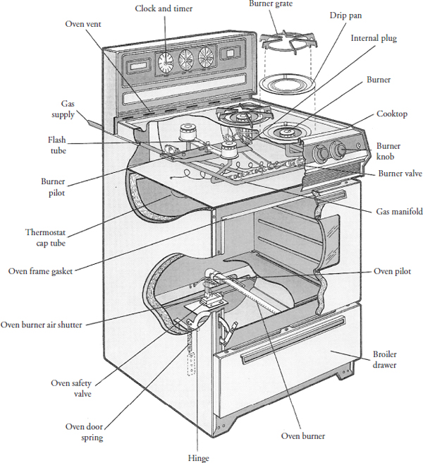
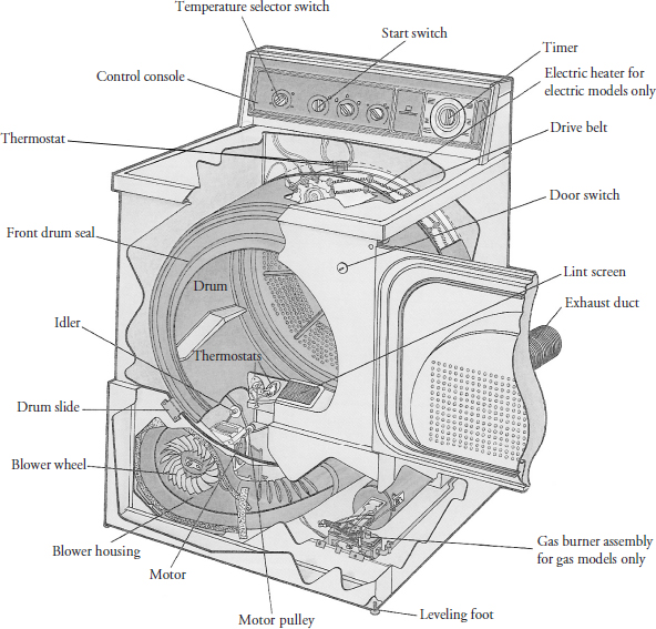
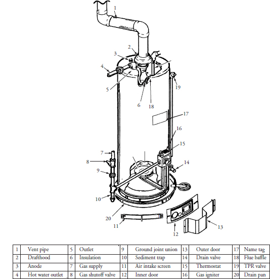
This chapter explains how to identify, locate, and understand the operation of gas appliance parts. In addition to electrical parts, the gas components play an important role in the proper operation and safety of gas appliances. Figures 12-1, 12-2, and 12-3 will help you to identify and locate the parts in a gas range, gas dryer, and gas water heater, respectively. Gas parts are divided into the following groups:
• Control parts: Manual and automatic controls used in gas appliances to turn the gas supply on or off or to regulate the flow of gas in the appliance.
• Safety parts: Gas controls that prevent a hazardous condition.
• Combination parts: Gas controls that act as both control parts and safety parts.
• Sensing parts: Sensing devices that are used to activate or deactivate a control.
• Ignition parts: Gas appliances require an ignition source to ignite the burners.
FIGURE 12-1 Typical gas range parts identification.
FIGURE 12-2 Typical gas dryer parts identification.
FIGURE 12-3 Typical gas water heater parts identification.
Gas appliance parts are factory-set upon installation and manufacture of the product. These settings should not be tampered with, unless it is determined that the setting was improperly set. It is recommended that you adjust the factory setting according to the manufacturer’s recommendation.
Controls
Manual and automatic controls are the two types of controls used in major appliances. Manual controls are operated by the consumer and are adjusted by eyesight. For example, a consumer will manually turn on a gas burner and adjust the flame height with the burner knob. Automatic controls require three elements to control the gas flow:
• A device to sense the operating conditions
• A device to regulate the flow of gas
• A means to actuate the control
Over the years, controls have evolved from simple controls to complex electronic systems using microprocessors that provide integrated control over all of the components in an appliance.
Pressure Regulator Controls
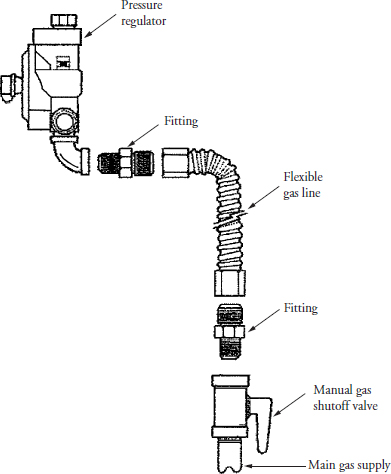
The pressure regulator (Figures 12-4, 12-5, and 12-6) is either a mechanical or electric control that regulates and maintains gas flow. This device reduces the incoming gas pressure to a level that is desired for a particular application. It is recommended that a main shutoff valve be installed between the pressure regulator valve and the main gas supply entering the appliance (Figure 12-7). With the shutoff valve located near the appliance, the technician will be able to shutoff the gas supply to the product before beginning repairs.
FIGURE 12-4 A gas pressure regulator valve.
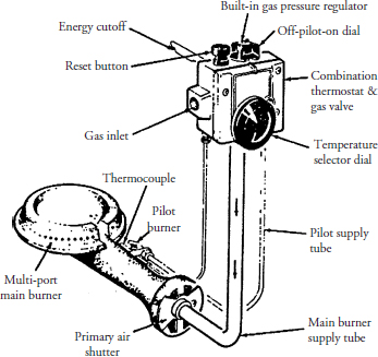
FIGURE 12-5 A water heater combination control. This control includes a gas pressure regulator valve, thermostat, and ignitor.
FIGURE 12-6 Two types of dryer gas valves.
FIGURE 12-7 The main gas supply line to an appliance should include a manual gas shutoff valve. If you intend to use a flexible gas line, you must check local building codes first.
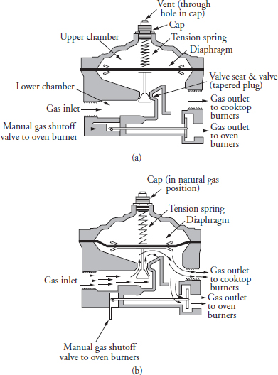
As the gas enters the pressure regulator valve (see Figure 12-4 and Figure 12-8a), the gas pressure pushes against the spring-loaded diaphragm, forcing the valve to close and shutting off the supply of gas to the appliance. When the consumer turns on the appliance, or when the appliance itself is calling for more gas, the pressure within the pressure regulator valve (Figure 12-8b) decreases, allowing the spring tension to push down on the diaphragm and forcing the valve to open, allowing more gas to the burner(s). The design of the tapered plug and diaphragm allows for metering and maintaining a constant pressure of gas to the burner(s). Another feature incorporated into the pressure regulator is an air vent in the upper chamber. The main purpose of this air vent is to allow air to enter and leave the upper chamber during the operation of the pressure regulator. As a secondary feature, the vent will allow gas to escape at a predetermined amount if the diaphragm ever ruptures.
FIGURE 12-8 (a) An illustration of a gas pressure regulator valve in the closed position. (b) An illustration of a gas pressure regulator valve in the open position.
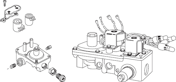
Dryer gas valves (see Figure 12-6) contain a pressure regulator and two solenoid-operated gas valves. During normal operation, both solenoid valves are energized simultaneously to allow gas to flow to the burner.
When diagnosing a pressure regulator failure, common causes to consider include:
• The valve portion within the regulator may have worn out or may be broken.
• Accumulation of dirt and debris around the valve seat can cause erratic operation or a complete shutdown of the regulator valve.
• The air vent might be plugged or restricted.
• The diaphragm has ruptured and gas is venting into the atmosphere.
• With LP gas, corrosion can occur within the regulator valve if water enters the gas supply.
• An electrical component may have failed.
Pressure regulator valves and dryer gas valves are not serviceable and should be replaced with a duplicate of the original if they fail.
Water Heater Thermostat/Regulator Combination Control
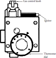
Water heaters use a combination control that incorporates a thermostat and a gas pressure regulator in one control (see Figure 12-9). In addition, the control has a gas cutoff device incorporated into the control in the event that the thermostat fails to shut off the gas supply. The combination valve is activated by a thermocouple that opens the gas inlet to the pressure regulator. The temperature probe will actuate a lever from within the pressure regulator to open or close the valve to the main burner. On top of the control is a knob that you will depress or turn, depending on the type of control, to begin the process to light the pilot light. If any part of this control fails, it is not serviceable and should be replaced with a duplicate of the original.
FIGURE 12-9 A water heater combination control valve.
Safety Valve
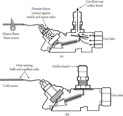
Ovens with a standing pilot-light ignition system have a safety valve (Figure 12-10) that controls the gas flow. The safety valve’s main function is to allow the gas coming from the thermostat to enter the oven burner. In Figure 12-10a, as the pilot flame heats up the safety valve sensor, the mercury-filled sensor expands and forces the switch to open the safety valve, allowing the gas to enter the oven burner. When the temperature in the oven is satisfied, the sensor begins to cool down, closing the safety valve (Figure 12-10b), stopping the gas flow to the oven burner. The safety valve and the oven thermostat must work together to operate the oven burner correctly. Further discussion on the thermostat and safety valve operation will be covered in a later chapter.
FIGURE 12-10 (a) The single gas safety valve in a standing pilot system in the open position. (b) The single gas safety valve in a standing pilot system in the closed position.
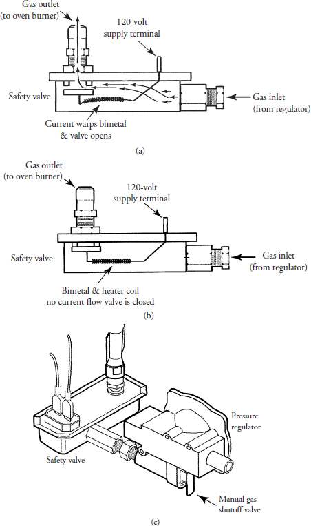
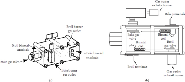
Ovens that have a glow-bar ignition system use a bimetal-operated safety valve (Figure 12-11). This type of valve has one gas inlet and one gas outlet. It is used for the bake burner and the broil burner combination. At the outlet end of the safety valve, there is an electrically operated bimetal strip with a rubber seat that covers the outlet, preventing the flow of gas at room temperature. When current is applied to the bimetal strip, it will warp, allowing the safety valve to open. Gas ranges with the self-cleaning feature in a single oven cavity have a dual safety valve (Figure 12-12). This valve will allow the gas to flow to the bake and broil burners separately when needed. It will not operate both burners at the same time. The operation of the dual safety valve is similar to the single safety valve.
FIGURE 12-11 (a) The single gas safety valve in a glow-bar ignition system in the open position. (b) The single gas safety valve in a glow-bar ignition system in the closed position. (c) A bimetal single safety gas valve and gas regulator connected together in an automatic ignition system.
FIGURE 12-12 (a) A dual safety gas valve. (b) An internal view of a dual safety gas valve.
When diagnosing a safety valve failure, common causes to consider include:
• A broken capillary tube
• Loss of voltage to the safety valve
• Bimetal and heater coil failure from within the safety valve
• Debris buildup around orifice
• Mechanical failure
Safety valves are not serviceable and should be replaced with a duplicate of the original if they fail.
Dryer Gas Valve
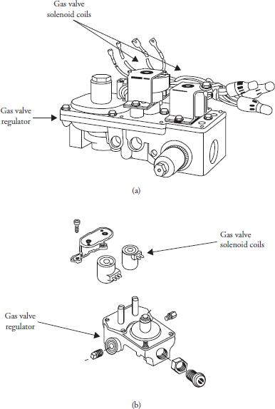
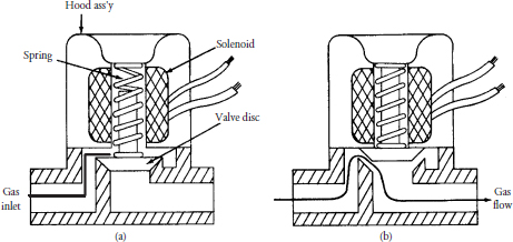
The dryer gas valve in Figure 12-13 is a combination control consisting of a pressure regulator and dual shutoff valves, housed in one body to regulate the gas flow when the thermostats call for more heat. The solenoid coils (Figure 12-14) will activate by means of electrical power and open the gas valves by electromagnetism, allowing gas to flow to the burner. When the temperature is satisfied, the electrical power is turned off and the solenoid coils deactivate, allowing the internal spring pressure to close the valve. Dryer gas valves are not serviceable; only the solenoid coils are serviceable. The gas valve body should be replaced with a duplicate of the original if it fails.
FIGURE 12-13 Two different designs of a dryer gas valve combination.
FIGURE 12-14 (a) A de-energized solenoid coil in a dryer gas valve assembly indicating no gas flow. (b) An energized solenoid coil in a dryer gas valve assembly indicating the flow of gas.
Sensing Devices
A sensing device can be a temperature-responsive or pressure-responsive device that transmits a signal or motion to activate or deactivate a control device. In electrical control circuits, resistive coils, resistance temperature detectors (RTD), and thermistors are used in a circuit to activate or deactivate the controls. The electrical resistance of these devices varies by temperature change to control current flow.
Resistance Temperature Detector
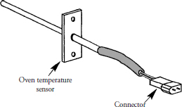
The resistance temperature detector (RTD) sensor operates on the principle that as the temperature increases, the resistance in the metal increases. With a constant voltage, the current through the metal will drop off as the temperature increases. Ovens with electronic control circuits use an oven temperature sensor (Figure 12-15) to activate or deactivate the bake, broil, and self-clean functions. This sensor is an RTD composed of a stainless steel tube coated with platinum at one end, and two wires connected to a connector that plugs into the electronic circuitry. The location of the sensor is in the upper corners of the oven cavity. This device is neither adjustable nor repairable, and should be replaced with a duplicate of the original if it fails.
FIGURE 12-15 A resistance temperature detector (RTD).
Thermocouple
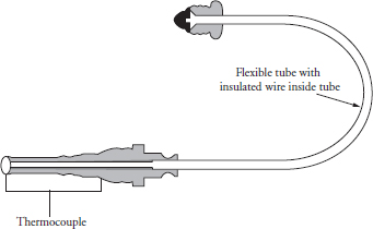
A thermocouple (Figure 12-16) is a measuring device consisting of two dissimilar metals, which produces a low DC voltage when heated by a gas pilot flame that is measured in millivolts. This thermoelectric device is commonly used in gas appliances to power automatic-pilot safety devices. The average output voltage for a single thermocouple is between 20 to 30 millivolts. If the thermocouple voltage drops below 5 millivolts, which can vary in design from manufacturer to manufacturer, the pilot safety device will shut off the gas supply to the burner. This device is neither adjustable nor repairable, and should be replaced with a duplicate of the original if it fails.
FIGURE 12-16 A thermocouple.
Flame Sensors
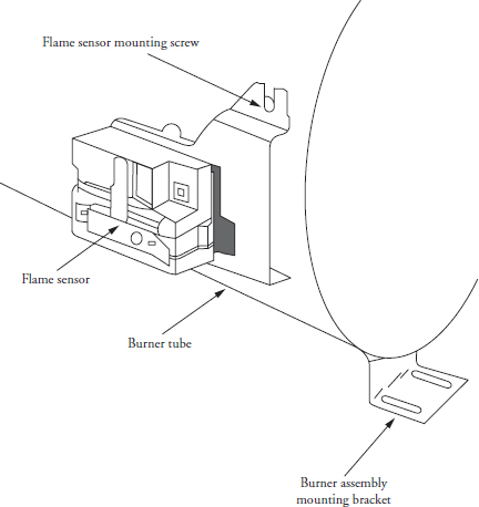
Flame sensors (Figure 12-17) are used in gas appliances to detect the presence of a pilot flame or the main burner flame. For safety reasons, in an automatic ignition system, it is required that a flame sensor be installed to detect the presence of a flame in the gas pilot or the main gas burner. Before the gas valve can open in an automatic pilot system, the flame sensor must detect the presence of the pilot flame. In an electronic ignition system (pilotless ignition), the flame sensor must be mounted over a window cut out in the burner tube to ensure that the burner flame is present or it will not allow the gas valve to open. The switch will open within 15 to 90 seconds if a flame is detected. Also, the ignitor temperature must be within 1800 to 2500 degrees Fahrenheit to open the gas valve. This device is neither adjustable nor repairable, and should be replaced with a duplicate of the original if it fails.
FIGURE 12-17 A flame sensor is a thermostatically controlled single pole, single throw, normally closed switch.
Ignition
There are two ways to ignite a gas burner: using matches or using an automatic ignition source. Many appliances manufactured today have some type of automatic ignition source. This automatic system can be continuous, intermittent, interrupted, or a combination of these things.
Glow-Bar Ignitor
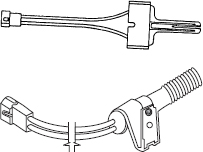
To achieve direct ignition, a silicon carbide glow-bar device (Figure 12-18) is positioned in the path of the burner flame. The reason for this positioning is to achieve the best performance for ignition and flame sensing. Line voltage is applied to the ignitor. When it reaches a temperature between 1800 and 2500 degrees Fahrenheit, in about 15 to 100 seconds (depending on design), a signal is sent to open the gas valve, allowing gas to flow to the burner, and gas ignition occurs. When using the glow-bar as a sensor, if the temperature of the glow-bar begins to drop below the ignition temperature, the gas valve will close, shutting off the gas supply to the burner.
FIGURE 12-18 Two types of a silicon carbide glow-bar device (ignitor) used in gas appliances.
There are times when the glow-bar ignitor will appear to glow properly and be reddish in color, but the gas burner will not light. In addition, there are times when the ignitor will not light at all. If this happens, you will need to perform a visual inspection and test the ignitor with a clamp-on multimeter. This ignitor is neither adjustable nor repairable, and should be replaced with a duplicate of the original if it fails.
Spark Electrode Ignitor
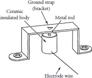
The spark electrode ignitor replaces the standing pilot flame system with electrodes and a spark module. The ignitor (Figure 12-19) consists of a metal rod embedded into a ceramic insulating body that is wired to a spark module located in the gas appliance. The spark module will send a number of pulses to the spark electrode ignitor, which will begin to arc between the metal rod and the grounding strap bracket. This device is neither adjustable nor repairable, and should be replaced with a duplicate of the original if it fails.
FIGURE 12-19 Type of ignitor used to light the gas burner(s) on a gas range.
Spark Module
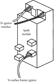
The spark module (Figure 12-20) is an electronic device that delivers a high-voltage pulse to the spark electrode ignitor. These pulses are delivered by a repeatable timing sequence from within the module every few seconds (depending on design) and operate at very low amperage. When a flame is detected, the spark module will stop transmitting pulses to the ignitor. Some gas appliance models are designed with automatic flame recovery and/or automatic lockout of the gas valve. This device is neither adjustable nor repairable, and should be replaced with a duplicate of the original if it fails.
FIGURE 12-20 A spark module.
