17
CHAPTER
Gas Water Heaters
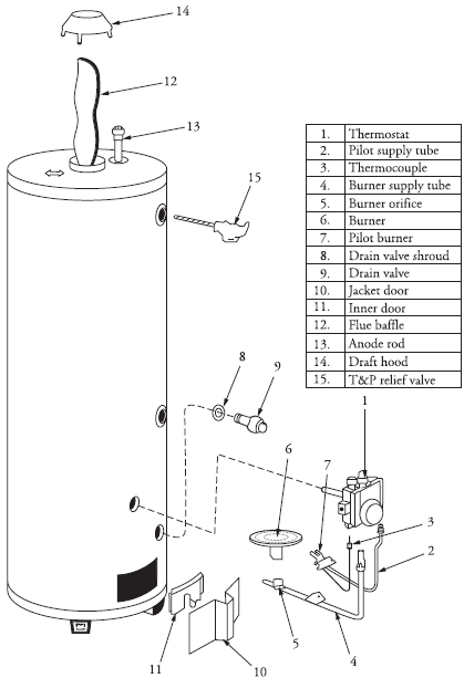
Gas water heaters are similar to electric water heaters, with the exception of how the water is heated. They use liquefied petroleum gas (LP or LPG) or natural gas to heat the water. The tank is constructed in such a way that it allows for a vent (chimney) up the middle of the tank, along with a gas burner on the bottom of the tank to heat the water (Figure 17-1). The thermostat that controls the water temperature and gas flow is mounted on the outside of the tank, with the temperature probes inserted into the tank to sense the water temperature. A temperature and pressure-relief valve, which is mounted on the outside of the tank, is a device applied to a water heater that will open to pass water or steam if excessive pressure or temperature occurs in the water heater tank.
FIGURE 17-1 Exploded view of a gas water heater.
Gas water heaters are available in many different sizes. When purchasing a gas water heater, it is important to specify the type of gas fuel that will be used to heat the water.
Principles of Operation
The gas water heater fills up in the same way as an electric water heater. Water enters the cold-water inlet port through a dip tube, filling the tank from the bottom up. Once the tank is full of water, the gas supply is turned on and the consumer or technician can begin the process of lighting the burner according to the manufacturer’s use and care manual. Once the pilot light is lit, the thermocouple, which is near or in the gas flow, will begin to heat up and send a signal to the gas combination valve to open the gas inlet to the pressure regulator section of the combination control valve. At the same time, the thermostat senses the cold water and sends a signal to the combination control to actuate a lever from within the pressure regulator to open the gas valve, allowing the gas to enter the burner for ignition. While the gas flames are heating the water, the thermostat begins monitoring the water temperature. When the water temperature reaches a preset temperature, a signal will be sent to the combination valve to Shutoff the gas flow.
Safety First
Any person who cannot use basic tools or follow written instructions should not attempt to maintain or repair any gas water heaters. Any improper installation, preventive maintenance, or repairs could create a risk of personal injury, death, or property damage.
If you do not fully understand the preventive maintenance or repair procedures in this chapter, or if you doubt your ability to complete the task on your gas water heater, please call your service manager.
These precautions should also be followed:
• Before servicing the water heater, turn off the gas supply.
• Never turn on the gas to the water heater if the tank is empty; do so only after it is full of water.
• At least once a year perform maintenance on the water heater according to the manufacturer’s recommendations.
• If a water heater needs to be replaced, it is strongly recommended that all gas connections, plumbing, ventilation, and placement of the tank be done by qualified personnel. Observe all local codes and ordinances for gas fuels, venting, plumbing, and installation procedures.
Before continuing, take a moment to refresh your memory concerning the safety procedures in Chapter 2. In addition, please follow the manufacturer’s recommendations for safety as outlined in the use and care manual.
Do not store any flammable materials near a gas water heater, and avoid ignition sources in the event you smell gas leaking. Make sure you have proper ventilation when servicing the water heater to prevent carbon monoxide (CO) poisoning.
Gas Water Heaters in General
Much of the troubleshooting information in this chapter covers gas water heaters in general, rather than specific models, in order to present a broad overview of service techniques. The pictures and illustrations that are used in this chapter are for demonstration purposes only, to clarify the description of how to service these heaters. In no way do they reflect on a particular brand’s reliability.
Gas Water Heater Maintenance
Maintenance on gas water heaters must be performed annually. The following checklist will assist you in performing the maintenance procedures:
1. A visual inspection must be made to the following components:
• The venting system A properly working ventilation system will prevent toxic fumes from entering the home. Check the venting system for leakage, corrosion, obstructions, sooting, and rust forming on top of the water heater. If any of these conditions are present, you must take action to correct these problem areas to protect the health and lives of the people living in the home. Most important, check the fitting (vent cap) on the end of the vent pipe for obstructions.
A properly designed and working vent system will convey the combustion gases from the water heater environment to the atmosphere outside of the home. It will also protect the home from fire hazards due to overheating of walls and other surfaces, prevent condensation of hot combustion gases, and provide clean air circulation and adequate oxygen supply for the water heater.
Check for adequate air supply to the area in which the water heater is located. A gas water heater will consume about 12.5 cubic feet of air (at sea level) for every 1000 BTUs of heat generated.
• The burner components Inspect the burner assembly and the pilot assembly. If your inspection reveals that the burner, pilot, or base assemblies need cleaning, turn off the gas supply and remove the burner and pilot assemblies for cleaning. Some models have a removable screen at the bottom of the tank that keeps dust, lint, and oils from entering the combustion chamber. This filter screen must also be cleaned.
• Surrounding area Clean the area surrounding the water heater of dust, lint, and debris. Make sure that combustible materials are removed completely from the area.
2. Inspect the temperature and pressure-relief valve (T&P) for leaks. If it is leaking water, you must replace it. Make sure that the valve is connected to a drain line that terminates to a drain or to the outside of the residence. Next, you will manually operate the T&P valve and check for proper operation. Be careful—the discharged water is very hot. Lift the T&P lever gently and then release it—the lever should return to its normal closed position. If the water is still leaking out of the valve after you release the lever, replace the valve.
3. Once a year, the water heater tank should be drained and flushed out. This procedure will increase the life expectancy of the tank by removing the unwanted sediment. Before you begin draining the tank, turn off the gas supply to the water heater. To drain the water heater tank, turn off the water supply to the tank. Connect a garden hose to the draincock, and open the valve. To increase the water flow draining out of the tank, open the hot water faucet—this will increase the flow of water draining out of the tank. When you are ready to refill the tank, close the draincock, turn on the water supply to the water heater, and begin to refill the tank.
Leave the closest hot water faucet open during refilling; the air that is trapped in the tank will escape through the hot water faucet. When all of the air is out of the tank and water lines, close the hot water faucet. Go to all of the other hot water faucets, and open them to remove the air in the lines. Close all water faucets. Now you are ready to turn on the gas supply to the water heater. Light the pilot light according to the manufacturer’s use and care guide for the model you are servicing.
Thermal Expansion
When water is heated in the water heater tank, it will expand. There is a physical law that states that as the water temperature rises, the water will expand in volume. For example, heating 40 gallons of water to the temperature setting on the thermostat will cause it to expand to 40.5 gallons when the temperature is reached. In the old days, before backflow preventers, water meter check valves, and pressure reducing valves, the excess water flowed back to the city main water supply where it was dissipated. Today, with the added controls and safety valves, the water cannot return to the city water supply. The water in the tank is in a “closed loop system” and has nowhere to go. The thermal expansion of the heated water causes a serious problem to the tank and the residence. The internal pressures in the water heater tank during recovery periods can stress the tank, causing the tank welds and fitting connections to the tank to weaken and fail, in turn causing flooding in the residence and possibly even bodily injury.
WARNING Water + heat + pressure + closed loop system = potential explosion and water damage!
As the pressure builds up in the water heater tank, the temperature pressure relief valve (T&P valve) will open and the excess water will be released from the water heater tank, either on the floor or drained to the outside of the residence. Even though the T&P valve opens during every recovery period, this action will weaken the tank and shorten its life. A good indicator of thermal expansion is when the T&P valve releases about one cup of water for every ten gallons of water in the tank for each heating period.
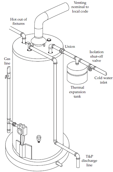
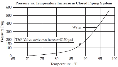
The best way to control thermal expansion in a water heater tank is to install a thermal expansion tank, shown in Figure 17-2. The thermal expansion tank will accept the excess water and pressure away from the water heater tank, store it, and return the excess water back to the water heater tank in the “closed loop system” as the water is used. This will prolong the life of the water heater tank. Also, the expansion tank will prolong the life of the temperature pressure relief valve. Figure 17-3 illustrates that water at 70° F in a water heater tank, with no pressure on the tank, will begin to rise in pressure when heated.
FIGURE 17-2 A thermal expansion tank installed to prevent water heater damage and flooding.
FIGURE 17-3 This figure points out the danger of what happens to the water pressure when heated in a closed loop system.
Water Hammer
When the hot or cold water valve is turned off quickly, a loud banging noise can be created. This noise is called a water hammer. If you close the water valve slowly, you will not hear a water hammer noise. A water hammer noise occurs when the water in a closed loop system comes to an abrupt stop at the water valve; a high-pressure shockwave reverberates within the piping system until the energy has been spent in frictional losses.
To prevent a water hammer condition, a water hammer arrestor device will have to be installed. These are designed so the water in the closed loop system will not contact the air cushion in the arrestor. This phenomenon is not a water heater issue; it is a plumbing issue. If a water hammer arrestor needs to be installed, contact a certified plumber.
Negative Air Pressure
Air pressure in a residence is affected by different forces, such as blowing wind, forced-air furnaces, clothes dryers, bathroom fans, range hoods, fireplaces, ceiling fans, and even the central vacuum cleaner. When the air pressure inside a residence is greater than the outside pressure, it’s called positive pressure. When the pressure in a residence is less than the outside pressure, it’s called negative pressure. Any device that can pull air out of a residence can create a negative pressure inside.
Over the past two decades, construction techniques have improved the energy efficiency of buildings, making them tighter and resistant to air leaks. The tighter the building, the greater potential for negative air pressure. This might leave you with a problem: combustion and ventilation air is not able to infiltrate into the building and combustion appliances and heating furnaces will be starved for air. There may be no air left in the building to operate the other devices such as exhaust fans. When this happens, the negative air pressure inside the building draws air in through every crack and crevice it can find to equalize the inside pressure.
Under normal conditions with positive air pressure in the building, the gas water heater will be able to vent the combustible by-products (flue gases) and the heat from the gas burner through the vent system to the outside of the building. When you have negative air pressure in the building, the combustible by-products (flue gases) and the heat from the burner will not vent to the outside. Instead, the vent system will act as a fresh air intake source. The flue gases and heat will stay in the structure, causing poor water heater performance and harmful gases to the occupants. Symptoms of negative air pressure problems are:
• The pilot flame will not stay lit.
• There will be flame rollout at the bottom of the water heater.
• Around the bottom of the heater there will be sooting.
• Slow recovery of the water heater.
The only places to find negative air pressure in a residence are the kitchen and laundry area. In the kitchen there might be an exhaust fan over the range venting air to the outside of the structure. In the laundry area, a gas dryer will vent moist air to the outside of the building.
Draft Test
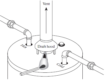
To check and see if the gas water heater is venting properly, perform a draft test (Figure 17-4). This test only applies to a natural vent system, and does not apply to the forced vent system water heater. Symptoms of a blocked vent include:
FIGURE 17-4 To determine if the vent system is working in an atmospherically vented gas water heater, perform a draft test.
• There are smells of combustion gases in the room.
• There is melted pipe insulation around the cold and hot nipples on the tank.
• Around the draft hood there are burn or scar marks, as well as paint peeling on the top of the tank and directly under and around the draft hood.
To conduct a draft test, perform the following:
1. Turn the thermostat up high on the combination valve until the burner comes on.
2. Wait 3 to 5 minutes until the venting system gets warm.
3. Place a smoke source halfway between the bottom of the draft hood and the top of the water heater. A smoke source can be a match or an incense stick.
4. Observe how the smoke behaves. If the smoke is drawn into the vent system, then the vent system is okay. If the smoke blows toward you, then there is a venting problem that has to be corrected.
5. When you complete the test, return the thermostat back to its original position (around 120° F).
Step-by-Step Troubleshooting by Symptom Diagnosis
In the course of servicing an appliance, don’t tend to overlook the simple things that may be causing the problem. Step-by-step troubleshooting by symptom diagnosis is based upon diagnosing malfunctions, with their possible causes arranged into categories relating to the operation of the water heater. This section is intended only to serve as a checklist to aid you in diagnosing a problem. Look at the symptom that best describes the problem that you are experiencing with the water heater and then proceed to correct the problem.
Gas Odors
1. Check the pilot light.
2. Check for a gas leak in the supply line.
3. Check the ventilation system.
The Burner Will Not Ignite
1. Make sure that the gas supply to the water heater is turned on.
2. Check the gas line for debris. Also, check the pilot line for debris.
3. Check the line to the burner for a blockage. If blocked, locate the source and correct.
4. Check the thermostat setting. It may be set too low.
5. Test the value of the thermocouple; replace if necessary.
6. Test the thermostat; replace if necessary.
7. Check the installation and fresh air supply.
The Pilot Will Not Light or Stay Lit
1. Make sure that the gas supply to the water heater is turned on.
2. Check the gas pressure to the water heater.
3. Check for air or debris in the lines. Purge the gas line.
4. Check the pilot line and orifice for debris.
5. Test the thermocouple, thermostat, and ignitor. Replace if necessary.
6. Check for drafts that can extinguish the pilot.
7. Check the intake air for obstruction. This is the air that is needed for combustion.
8. Check for flammable vapors.
Not Enough Hot Water
1. Check the thermostat; it might be set too low.
2. Check the installation for correct piping connections. Is the tank adequate for the size of the household and usage?
3. Check the home for hot water leaking from the faucets. Did you notice any wasting of hot water? If so, speak to the consumer.
4. Where are the water pipes located? Are the pipes exposed to the elements? Are they insulated? Check on the length of the piping.
5. Check the tank for sediment or lime. You may have to flush out the tank.
Slow Hot Water Recovery
1. Check for insufficient secondary air supply. Check the venting system and the burner.
2. Check the gas pressure. Is the type of gas correct for the water heater?
3. Check the thermostat setting. Is it out of calibration?
4. If this is a new installation, check the piping connections.
5. Check for wasting of water.
6. Is the water heater the correct size for the household?
The Burner Flame Is Too High
1. Is the orifice too large? You can change the orifice and retest the burner.
2. Check for sufficient secondary air supply. Check the venting system and the burner.
The Flame Burns at the Orifice
1. Check the thermostat. Replace if necessary.
2. Check the gas pressure to the water heater.
The Pilot Flame Is Too Small
1. Check the pilot line and orifice for debris.
2. Check the gas pressure to the water heater.
The Burner Flame Floats and Lifts Off the Ports
1. Is the orifice too large? You can change the orifice and retest the burner.
2. Check for high gas pressure.
3. Check the flue and burner. Locate the source and correct the problem.
4. Check for drafts that can blow the flame off the burner.
A Yellow-Lazy Burner Flame
1. Check for sufficient secondary air supply.
2. Check the gas pressure.
3. Check the venting system. Is the flue clogged?
4. Check the burner line for debris.
5. Check the water heater installation. Is the tank installed in a confined space?
6. Check the burner orifice for obstruction.
The Formation of Soot (Smoke and Carbon)
1. Check for sufficient secondary air supply.
2. Check the flue way, flue baffle, and burner.
3. Test the draft hood for proper ventilation.
4. Check for a yellow-lazy burner flame.
5. Check for low gas pressure to the water heater.
6. Check the thermostat. Replace if necessary.
7. Is the water heater installed in a confined space?
Condensation
Check the thermostat setting. Is it set too low?
The Water Has an Odor
Check for sulfides in the water. If necessary, replace the anode.
The Water Heater Jacket Is Discolored Above the Combustion Area
1. Check that the burner orifice is the proper size.
2. Is the flue clogged?
3. Check for high gas pressure.
Combustion Odors
1. Check for sufficient secondary air. Check the flue way, flue baffle, and the burner.
2. Is the flue clogged?
3. Is the water heater installed in a confined space?
Repair Procedures
Each repair procedure is a complete inspection and repair process for a single water heater component. It contains the information you need to test a component that may be faulty and to replace it, if necessary.
Burner/Manifold Assembly
The typical complaints associated with the burner/manifold assembly are:
• No gas to the burner.
• Yellow-lazy burner flame.
• The flames lift off the burner ports.
• The burner will not ignite.
• High temperatures. Some models have a thermal cutoff device installed to prevent the gas flow if the temperature in the combustion chamber exceeds its limit.
• Poor maintenance. It’s time to clean the burner/manifold assembly.
To handle this problem, perform the following steps:
1. Verify the complaint. To verify the complaint, run the hot water. Does the burner come on? Check the thermal cutoff device. What color is the burner flame? Does the burner/manifold assembly need cleaning?
2. Check for external factors. You must check for external factors not associated with the water heater. Is the gas supply turned on? Is the water heater installed properly? Is there sufficient air supply? Is the surrounding area clear of debris?
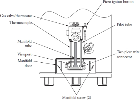
3. Shut off the gas supply. Before you begin servicing any gas components, shut off the supply of gas to the water heater. Turn the gas control knob on the combination gas control to the off position (Figure 17-5a). See the use and care guide for the model you are servicing.
FIGURE 17-5a Component identification and location on a gas water heater.
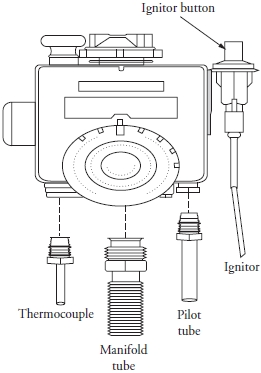
4. Remove the burner/manifold. Remove the screws that secure the manifold door to the skirt (see Figure 17-5a). At the combination gas control, disconnect the following: thermocouple, ignitor wire from the ignitor button, pilot tube, and the manifold tube (Figure 17-5b). Gently push down on the manifold tube to free the manifold, thermocouple, and pilot tube. Next, carefully remove the burner/manifold assembly from the burner compartment. Try not to damage any of the internal parts.
FIGURE 17-5b The combination control valve. The ignitor, thermocouple, manifold tube, pilot tube, and ignitor will have to be disconnected in order to remove the valve assembly.
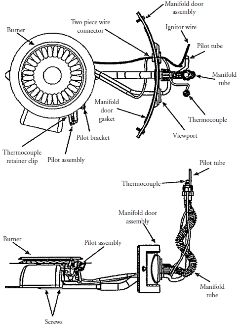
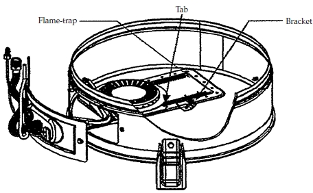
5. Clean the burner. Now that the burner/manifold assembly is removed from the water heater, you can inspect the burner and clean it. Disassemble the burner from the manifold assembly by removing the two screws that secure it to the manifold (Figure 17-6). To clean the burner, use soap and hot water, rinse, and let it dry. Clean the remainder of the manifold assembly with a brush, and blow off any debris from the flame trap. Inspect the pilot tube and the manifold tube for a blockage. Before reinstalling the burner/manifold assembly, clean out the combustion chamber (Figure 17-7) with a shop vacuum, making sure that you remove all of the loose debris. Some models are manufactured with a flame arrestor to prevent flames from escaping the combustion chamber. This component must also be cleaned with a vacuum to remove debris.
FIGURE 17-6 The top and side view of the burner/manifold assembly.
FIGURE 17-7 The burner/manifold assembly located in the combustion chamber.
6. Reinstall the burner/manifold assembly. To reinstall the burner/manifold assembly, just reverse the disassembly procedure. Before you get started, inspect the gaskets for wear and tear, and replace them if necessary. Reconnect the pilot tube, manifold tube, thermocouple, and ignitor wire. Next, turn on the gas supply and light the burner according to the manufacturer’s recommendations for the model you are servicing. Check for gas leaks by using a chloride-free soap solution. Do not use a flame to check for gas leaks. The soap solution will begin to bubble if a leak is present. If no leaks are found, you are ready to reinstall the outer door.
7. Test the water heater. Once assembled, run the water heater for a number of cycles by letting the hot water run for a while and then shutting it off. The water heater will begin cycling. Inspect the flame—it should be a blue flame. Adjust the air shutter as needed. On some models, you will have to remove the burner/manifold assembly to adjust the air shutter.
Combination Control Valve
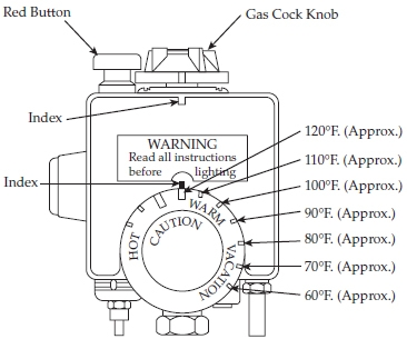
The combination control valve consists of a gas pressure regulator valve, thermostat, and ignitor. The combination control valve also has a gas cutoff device incorporated into the valve to shut off the gas supply in the event that the thermostat fails. In Figure 17-8, the thermostat does not have numbered temperature markings only notches that indicate 60 degrees and up.
FIGURE 17-8 The notches on the thermostat dial indicate approximately 10-degree increments starting from 60° F to the first index mark as shown.
The typical complaints associated with the combination control valve are:
• The burner will not ignite.
• Unable to control the water temperature.
• Slow hot water recovery.
• Smoke and carbon buildup (sooting).
• The combination control will not shut off the gas to the burner.
• Some models have a thermal cutoff device installed to prevent gas flow if the temperature in the combustion chamber exceeds its limit.
To handle this problem, perform the following steps:
1. Verify the complaint. To verify the complaint, check the burner operation. Test the water temperature and the thermostat setting. Does the burner cycle at the predetermined temperature? Check the thermal cutoff device. Check for sooting. Can you shut off the burner with the thermostat control knob?
2. Check for external factors. You must check for external factors not associated with the water heater. Is the water heater installed properly? Is there sufficient air supply? Is the surrounding area clear of debris? Is the ventilation system clear of debris?
3. Shut off the gas supply. Before you begin servicing any gas components, shut off the supply of gas to the water heater. Turn the gas control knob on the combination gas control to the “off” position (see Figure 17-5a). See the use and care guide for the model you are servicing.
4. Remove the combination gas control valve. Turn off the combination gas control valve according to the use and care guide for the model you are servicing. Turn off the main gas supply to the water heater. Before you can remove the control valve, you first have to drain the water heater tank. To drain the water heater tank, turn off the water supply to the tank. Connect a garden hose to the draincock, and open the valve. To increase the water flow draining out of the tank, open the hot water faucet—this will increase the flow of water draining out of the tank. While the tank is draining, disconnect the ignitor wire from the ignitor, and remove the ignitor button and bracket. Remove the manifold tube and pilot tube, and disconnect the thermocouple (see Figures 17-5a and 17-5b). Next, disconnect the ground joint union located between the gas shutoff valve and the combination valve. Disconnect the remaining pipe from the combination gas control valve. When the water heater tank is empty, you are ready to remove the control valve. Turn the valve counterclockwise and remove it from the tank.
5. Install the combination gas control valve. To install a combination gas control valve, just reverse the order of disassembly. Make sure that you use approved pipe joint compound or Teflon yellow tape on the pipe connections (according to local codes) and on the threads of the control valve before you install the valve into the water heater tank. This will prevent water from leaking out of the tank. Close the draincock and turn on the water supply to the tank, allowing it to fill up. Keep a faucet open near the tank to allow air to escape from it. As for the gas lines, you will perform a leak check using a chloride-free soap and water solution when the gas supply is turned back on. Finally, check for any water leaks before lighting the burner.
Thermocouple
A thermocouple is a measuring device consisting of two dissimilar metals, which produces a low DC voltage when heated by a gas pilot flame that is measured in millivolts. The average output voltage for a single thermocouple is between 20 and 30 millivolts.
The typical complaints associated with the thermocouple are:
• The burner will not ignite.
• The pilot light will not remain lit.
To handle this problem, perform the following steps:
1. Verify the complaint. To verify the complaint, check the burner operation. Does the burner come on? Check the pilot light. Is it lit?
2. Check for external factors. You must check for external factors not associated with the water heater. Is the water heater installed properly? Check the gas supply line. Is it turned on? Is there sufficient air supply? Is the surrounding area clear of debris?
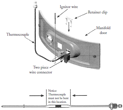
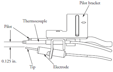
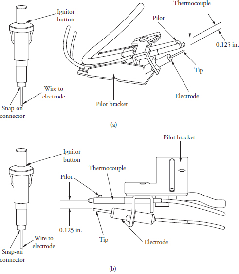
3. Remove the burner/manifold. Remove the screws that secure the manifold door to the skirt (see Figure 17-5a). At the combination gas control, disconnect the following: thermocouple, ignitor wire from the ignitor button, pilot tube, and the manifold tube (see Figure 17-5b). Gently push down on the manifold tube to free the manifold, thermocouple, and pilot tube. Next, carefully remove the burner/manifold assembly from the burner compartment. Try not to damage any of the internal parts. Remove the thermocouple two-piece connector by removing the retainer clip that secures the thermocouple connector to the manifold door (Figure 17-9). Disconnect the thermocouple from the pilot bracket (Figure 17-10).
FIGURE 17-9 The thermocouple assembly. Do not bend the thermocouple as indicated; it has an internal thermal fuse that could be damaged.
FIGURE 17-10 The thermocouple bracket assembly. The electrode must be positioned 0.125 inches from the pilot.
4. Install the new thermocouple. To install a new thermocouple, just reverse the order of disassembly. Insert the new thermocouple into the bracket holes until it clicks into place. Now you are ready to reinstall the burner/manifold assembly and test.
Ignitor
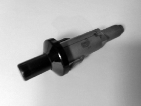
The typical ignitor that is used on gas water heaters is the piezoelectric ignitor (Figure 17-11). When the button on the ignitor is pushed down, it produces a spark at the burner.
FIGURE 17-11 A piezoelectric ignitor. This type of ignitor is used to ignite the gas burner.
The typical complaint associated with the ignitor is that the burner will not light or remain lit. To handle this problem, perform the following steps:
1. Verify the complaint. To verify the complaint, check the burner operation. Does the burner come on? Check the pilot light. Is it lit? Turn off the gas supply and observe the ignitor electrode when activating the ignitor. Do you see a spark at the ignitor?
2. Check for external factors. You must check for external factors not associated with the water heater. Is the water heater installed properly? Check the wiring connections and wiring. Is the ignitor electrode broken?
3. Remove the burner/manifold. Remove the screws that secure the manifold door to the skirt (see Figure 17-5a). At the combination gas control, disconnect the following: thermocouple, ignitor wire from the ignitor button, pilot tube, and the manifold tube (see Figure 17-5b). Gently push down on the manifold tube to free the manifold, thermocouple, and pilot tube. Next, carefully remove the burner/manifold assembly from the burner compartment. Try not to damage any of the internal parts. Remove the ignitor electrode from the pilot bracket (Figure 17-12a and b).
FIGURE 17-12 (a) The natural gas ignitor assembly. (b) The LP gas ignitor assembly.
4. Install the new ignitor. To install the new ignitor, just reverse the order of disassembly. When positioning the ignitor electrode in the pilot bracket, the spark gap should be 0.125 inches. Reinstall the burner/manifold assembly and test.
Water Heater Leakage Inspection Points
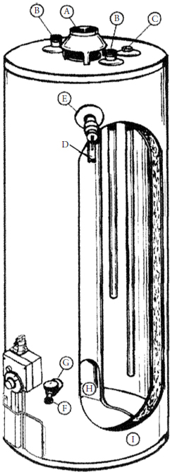
A technician must check the following areas for leakage when servicing the water heater (Figure 17-13):
FIGURE 17-13 Leakage inspection points on a gas water heater.
A. Check the draft hood for condensation. Water vapor that has formed from combustion products is an indication of a problem in the vent system. If this problem is not corrected, the top of the water heater will begin to rust.
B. On humid days, condensation may appear on the pipes and connections.
C. Check the anode rod fitting for leakage.
D. Check for leakage at the temperature and pressure-relief valve and piping. The leakage could be from thermal expansion or high water pressure to the household. If there is a steady stream of water coming from the valve, the temperature and pressure-relief valve may be defective.
E. Check for leakage from the temperature and pressure-relief valve fitting at the tank.
F. The drain valve may be leaking. Check if the valve is slightly open.
G. Check for leakage from the drain valve fitting at the tank.
H. Check for leakage in the combustion chamber. Combustion products that contain water vapor could form droplets in that area. When cold water enters the tank, condensation may form droplets in that area, too. These droplets can fall on the burner/manifold area, causing damage to the component. In addition, the droplets can run onto the floor. This usually happens on new installation startups.
I. Check the rim around the outside of the water heater tank for leakage, the water heater bottom, and on the floor. Check for leakage at all pipe connections and at the temperature and pressure-relief valve. Check and see if the temperature and pressure-relief valve discharge line is directed over a drain or runs to the outside of the residence. In some cases, I found the discharge line was draining on the floor and was not piped correctly.
Other possibilities for water leakage around the water heater tank can come from other appliances (for example, an automatic washer or air conditioner), water lines, and ground water seepage.
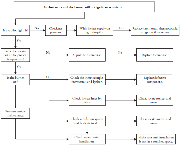
Diagnostic Charts
FIGURE 17-14 The diagnostic flowchart: No hot water and burner will not ignite or remain lit.
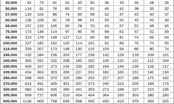
Table 17-1 illustrates how to figure the hot water recovery rate by hand when you know the BTU input located on the data tag:
TABLE 17-1 Recovery Rates in Gallons per Hour for Gas Water Heaters
Hourly input (BTU’s)
11.0 x temperature rise °F
Formulas and Facts
1 gallon of water weighs 8.33 lbs
1 gallon of water has a volume of 231 cubic inches
I cubic foot of water weighs 62.38 lbs and contains 7.48 gallons of water
100 feet of ¾-inch copper pipe contains 2.5 gallons of water; 1-inch pipe contains 4.3 gallons
8.33 BTU will raise 1 gallon of water 1°F at 100 percent efficiency (electricity)
11 BTUs are required to raise 1 gallon of water 1°F at 75 percent efficiency (gas)
3412 BTU equals 1 kilowatt hour (Kwhr)
1 Kwhr will raise 410 gallons of water 1°F at 100 percent efficiency
1 BTU × 0.293 = watts
1 KW = 1000 watts
2.42 watts are required to raise 1 gallon of water 1°F
1 Kwhr will raise 10.25 gallons of water 40°F at 100 percent efficiency
1 Kwhr will raise 6.8 gallons of water 60°F at 100 percent efficiency
1 Kwhr will raise 5.1 gallons of water 80°F at 100 percent efficiency
1 Kwhr will raise 4.1 gallons of water 100°F at 100 percent efficiency
Electric Water Heaters
Energy Costs:
Kwhr × fuel costs = energy costs
If I use 100 kilowatt hours of electricity, how much will it cost if each kilowatt hour costs $.05?
100 × .05 = $5.00
To obtain gallons per hour (GPH) recovery:
I have a 30-gallon electric heater, nonsimultaneous operation, 4500 watt elements. What is the recovery GPH if my cold water is 40° F and my thermostat is set to 120° F?
Temperature Rise (°F)
I have a 30-gallon electric heater, nonsimultaneous operation, 4500 watt elements. What is the maximum temperature rise if the heater can recover 23 gallons per hour?
Gas Water Heaters
Energy Costs:
Cubic feet × fuel costs = energy costs
If I use 100 cubic feet of gas, how much will it cost if each cubic foot costs $.075?
100 × .075 = $7.50
To obtain gallons per hour (GPH) recovery:
I have a 30-gallon gas heater rated at 40,000 BTUs. What is the recovery GPH if my cold water is 40° F and my thermostat is set to 120° F?
Temperature Rise (°F)
I have a 30-gallon gas heater rated at 40,000 BTUs. What is the maximum temperature rise if the heater can recover 45 gallons per hour?
Formula for Mixing Hot Water
where M = mixed water temperature, C = cold water temperature, H = hot water temperature. For example: How much of a shower is hot water and how much is cold water? My shower temperature is 105° F, my water heater thermostat is set on 120° F, and the cold water inlet temperature is 50° F.
This formula for mixing hot water is important when explaining to a customer why there might not be enough hot water when the water heater is functioning properly.
Electric Working Formulas That Apply to Water Heaters
To verify circuit breaker or amperage draw on the water heater:
Amperage draw = 18.8 amps (circuit breaker should be 20% higher or 25 amp breaker)
Now that you have solved amperage, what is the resistance (Ohms) of the heating element? (If a heating element has no resistance, then it is open, or broken.)
Resistance = 12.8 Ohms
Help on the Internet
To obtain additional technical help or information on selecting a gas water heater, you can go to the following websites:
