6
CHAPTER
Electricity
The technician must be knowledgeable in electrical theory to be able to diagnose and repair major appliances and air conditioners properly. Although this chapter cannot cover all there is to know about electricity, it provides the basics. In the field of major appliances and air conditioners, the greatest number of potential problems is in the electrical portions of the product.
Electrical Wiring
The flow of electricity from a power source to the home can be made easier to understand by comparing it to a road map. Electricity flows from a power source to a load. This is similar to a major highway that runs from one location to another.
High-voltage transformers are used to increase voltages for transmission over long distances. The power lines that go to different neighborhoods are like the smaller roads that turn off the major highway. The electricity then goes to a transformer that reduces the voltage going into the home. This is the intersection between the small roads and the medium-sized highways. The small road that goes into the neighborhood, and all the local streets, are like the wiring that goes inside the home.
When all the streets, roads, and highways are connected together, the city is accessible. This is similar to having electricity flowing from the power source to all of the outlets in the home.
Imagine driving down a road and coming to a drawbridge (in this case, the switch), and it opens up. This stops the flow of traffic (electricity). In order for traffic (or electricity) to flow again, the drawbridge must close.
What Is a Circuit?
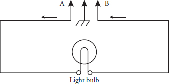
A circuit is a complete path through which electricity can flow and then return to the power source. Figure 6-1 is an example of a complete circuit. To have a complete path (or closed circuit), the electricity must flow from Point A to Point B without interruption.
FIGURE 6-1 The complete circuit. Current flows from Point A, through the light bulb, and then back to Point B.
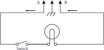
When there is a break in the circuit, the circuit is open. For example, a break in a circuit is when a switch is turned to its “off” position. This will interrupt the flow of electricity, or current, as shown in Figure 6-2. When a broken circuit is suspected, it is necessary to discover the location of the opening.
FIGURE 6-2 With the switch open, the current flow is interrupted.
Circuit Components
In an appliance or air conditioner, an electric circuit has four important components:
• Power source This source might be a battery or the electricity coming from the wall outlet. Without the applied voltage, current cannot flow.
• Conductors A conductor will usually be a wire and sometimes the metal chassis (frame). The function of the wire conductor is to connect a voltage source to a load.
• Loads These are the components that do the actual work in the appliance or air conditioner. A load is anything that uses up some of the electricity flowing through the circuit. For example, motors turn the belt, which turns the transmission. That, in turn, turns the agitator in a washing machine. Other examples are heating elements and solenoids.
• Controls These control the flow of electricity to the loads. A control is a switch that is either manually operated by the user of the product or operated by the appliance or air conditioner itself.
Three Kinds of Circuits
You will come across three kinds of circuits: series circuits, parallel circuits, and series-parallel circuits (a combination of series and parallel circuits).
Series Circuit
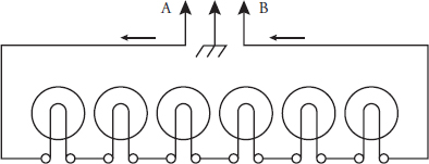
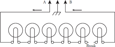
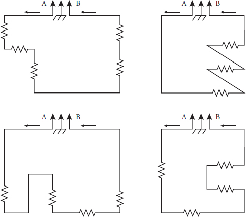
The components of a series circuit are joined together in successive order, each with an end joined to the end of the next (Figure 6-3). There is only one path that electricity can follow. If a break occurs anywhere in the circuit, the electricity, or current flow, will be interrupted and the circuit will not function (Figure 6-4). Figure 6-5 shows some of the many different shapes of series circuits, all of which are used in wiring diagrams. In each series circuit, there is only one path that electricity can follow. There are no branches in these circuits where current can flow to take another path. Electricity only follows one path in a series circuit.
FIGURE 6-3 A series circuit.
FIGURE 6-4 If there is a break in the wiring, all of the light bulbs will be off.
FIGURE 6-5 When you look at wiring diagrams, you will find series circuits in all sorts of shapes.
Parallel Circuits
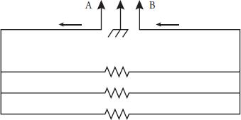
The components of a parallel circuit are connected across one voltage source (Figure 6-6). The voltage to each of these branches is the same. The current will also flow through all the branches at the same time. The amount of current that will flow through each branch is determined by the load, or resistance, in that branch.
FIGURE 6-6 Parallel circuit.
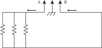
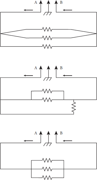
Figure 6-7 and Figure 6-8 show examples of parallel circuits. If any branch has a break in it, the current flow will only be interrupted in that branch. The rest of the circuits will continue to function.
FIGURE 6-7 Another parallel circuit.
FIGURE 6-8 Notice that as in series circuits, the same parallel circuit can be drawn in many different ways.
Series-Parallel Circuits
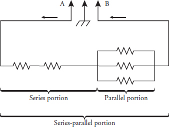
A series-parallel circuit is a combination of series circuits and parallel circuits. In many circuits, some components are connected in series to have the same current, but others are in parallel for the same voltage (Figure 6-9). This type of circuit is used where it is necessary to provide different amounts of current and voltage from the main source of electricity that is supplied to that appliance.
FIGURE 6-9 Series-parallel circuit.
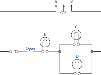
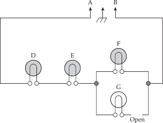
Series and parallel rules apply to this type of circuit. For example, if there is a break in the series portion of the circuit (Figure 6-10), the current flow will be interrupted for the entire circuit. If the break is in the parallel portion of the circuit (Figure 6-11), the current will be interrupted for only that branch of the circuit. The rest of the circuits will still function.
FIGURE 6-10 Series-parallel circuit with open in the series portion of the circuit. No current flow in the entire circuit.
FIGURE 6-11 Series-parallel circuit with open in the parallel portion of the circuit. Current flows through D, E, and F, but not through G.
Types of Shorts in a Circuit
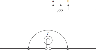
When a short occurs in a series circuit, it means there is zero resistance across an electrical source. Figure 6-12 shows a wire across load C. This short, which is the path of least resistance, allows the current to flow through the wire instead of the load.
FIGURE 6-12 A wiring short in a series circuit.
A short can be added to part of the series circuit to bypass one or more of the loads in the circuit. This type of short is referred to as a “shunt.” Manufacturers can design this shunt into a circuit. The difference between a “short” and a “shunt” is as follows:
• With a short, there is no resistance to the flow of current in a circuit.
• A shunt will form a bypass around the load(s), but the circuit will still offer resistance to the flow of current.
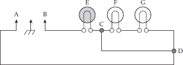
In Figure 6-13, if a short is connected in the series circuit between C and D, the loads E, F, and G would by bypassed because they are shorted out of the circuit. Electricity takes the path of least resistance.
FIGURE 6-13 A series circuit with a short across loads E, F, and G.
In Figure 6-14, if a permanent shunt was connected in the series circuit between points C and D, loads F and G would be bypassed because they were shorted out of the circuit.
FIGURE 6-14 A series circuit with a permanent shunt across loads F and G.
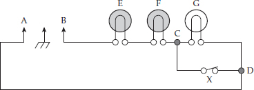
In Figure 6-15, if the manufacturer designed a load to be turned on and off, they will install a switch to act as a shunt across a load. When switch X is closed, load G is turned off, allowing loads E and F to remain on.
FIGURE 6-15 A series circuit with a switch acting as a temporary shunt across load G.
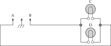
In Figure 6-16, the parallel circuit will allow current to flow from point A through the loads C and D, and back to point B.
FIGURE 6-16 A parallel circuit with two loads.
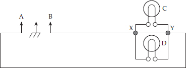
In the parallel circuit in Figure 6-17, a short was placed between points X and Y, shorting out loads C and D. The current will flow from point A through the loads and through the shorted wire back to point B. Remember, electricity takes the path of least resistance.
FIGURE 6-17 A parallel circuit with a short between loads C and D.
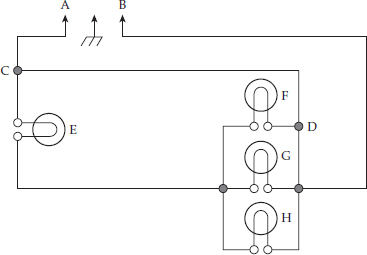
In the series-parallel circuit in Figure 6-18, the current will flow from point A, through the short beginning at point C, to point D, and back to point B, bypassing loads E, F, G, and H. Keep in mind that electricity takes the path of least resistance.
FIGURE 6-18 A series-parallel circuit with a short.
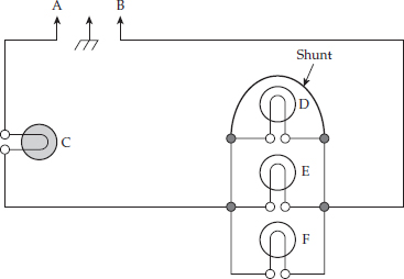
In Figure 6-19, current will flow through the series portion of the circuit from point A through the load C. In the parallel portion of the circuit, current will flow from load C through the wire (shunt) across load D, and back through point B. The three loads would be bypassed. Electricity takes the path of least resistance.
FIGURE 6-19 A series-parallel circuit with a shunt.
Strip Circuits
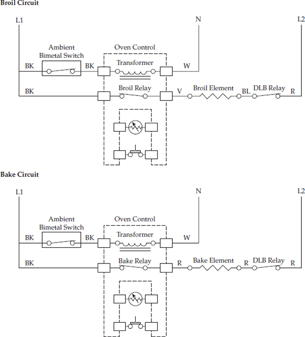
A strip circuit is a piece of the whole circuit; it is easy to use as a diagnostic tool. When you compare a strip circuit (Figure 6-20) to a complete standard wiring diagram, you will notice many different components. In the wiring diagram, it can be confusing to figure out the active circuits to diagnose. In the strip circuit in Figure 6-20, only the circuits needed for an active broil and bake circuit are shown. You read a strip circuit from left to right, which makes it easier to read and to diagnose the circuit.
FIGURE 6-20 A broil and bake strip circuit.
Types of Electric Current
There are two types of electric current:
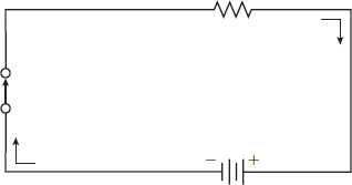
• Direct current (DC) flows continuously in the same direction (Figure 6-21).
FIGURE 6-21 A simple DC electrical circuit. Current flows from the negative side of the battery through the switch and load, and back to the positive side of the battery.
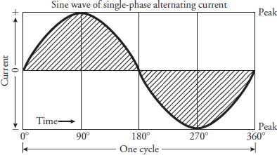
• Alternating current (AC) flows in one direction and then reverses itself to flow in the opposite direction along the same wire. This change in direction occurs 60 times per second, which equals 60 Hz (Figure 6-22).
FIGURE 6-22 A waveform of a single-phase alternating current.
Direct current (DC) is used in automobile lighting, flashlights, and cordless electric appliances (such as toothbrushes, shavers, and drills), and in some major appliances and air conditioners.
Alternating current (AC) is used in most homes. This current can be transmitted more economically over long distances than direct current can. Alternating current can also be easily transformed to higher or lower voltages.
Theory of Current Flow
When servicing electronic solid-state circuits in major appliances or air conditioners, the technician should be aware that explanation of the circuit is often given assuming conventional current flow as opposed to electron flow. Conventional current flow theory states that current flow is from positive to negative. Electron current flow theory states that current flows from negative to positive.
Ohm’s Law
Ohm’s Law states (I = E/R): The current that flows in a circuit is directly proportional to the applied voltage and inversely proportional to the resistance. So, an increase in the voltage will increase the current as long as the resistance is held constant. Alternately, if the resistance in a circuit is increased and the voltage does not change, the current will decrease.
The second version states (E = I × R): It can be seen from this equation that if either the current or the resistance is increased in the circuit (while the other is unchanged), the voltage will also have to increase.
The third version states (R = E/I): If the current is held constant, an increase in voltage will result in an increase in resistance. Alternately, an increase in current while holding the voltage constant will result in a decrease in resistance.
In any of the three formulas, when two elements of the electric circuit are known, the unknown factor can be calculated.
Ohms
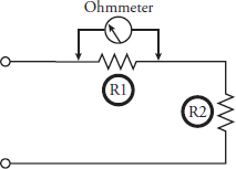
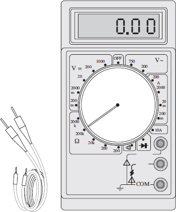
Resistance is measured in ohms and opposes the flow of electrons (current). An instrument that measures resistance is known as an ohmmeter. Figure 6-23 is a schematic showing an ohmmeter connected to read the resistance of R1. The resistance of any material depends on its type, size, and temperature. Even the best conductor offers some opposition to the flow of electrons. Figure 6-24 shows another type of meter, the digital multimeter, used for measuring ohms. The fundamental law used to find resistance is stated as follows: The resistance (R) in ohms is equal to the potential difference measured in volts (V), divided by the current in amperes (A). The equation is: R = V ÷ A.
FIGURE 6-23 An ohmmeter connected to read resistance.
FIGURE 6-24 A digital multimeter for measuring ohms.
Amperes
Current is measured in amperes. The term ampere refers to the number of electrons passing a given point in one second. When the electrons are moving, there is current. The ammeter is calibrated in amperes, which we use to check for the amount of current in a circuit.
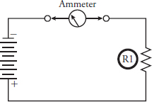
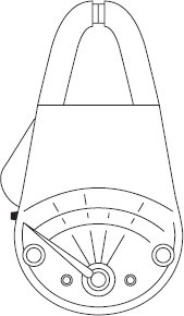
An instrument that measures amperes is known as an ammeter. Figure 6-25 is a schematic showing an ammeter connected in a circuit to measure the current in amperes. Figure 6-26 shows an ammeter that is used in diagnosing electrical problems with appliances. Current is the factor that does the work in the circuit (light the light, ring the buzzer). The fundamental law to find current is stated as follows: The current in amperes (A) is equal to the potential difference measured in volts (V), divided by the resistance in ohms (R). The equation is: A = V ÷ R.
FIGURE 6-25 An ammeter connected in a circuit, measuring amperes.
FIGURE 6-26 In the ammeter, the jaws clamp around a wire to measure the amperage of a circuit.
Volts
Electromotive force is measured in volts. This is the amount of potential difference between two points in a circuit. It is this difference of potential that forces current to flow in a circuit. One volt (potential difference) is the electromotive force required to force one ampere of current through one ohm of resistance.
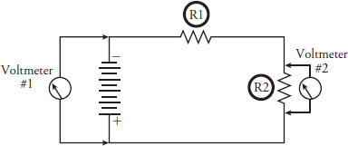
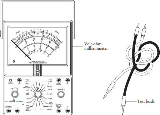
An instrument that measures voltage is known as a voltmeter. Figure 6-27 is a schematic showing a voltmeter connected in the circuit to measure the voltage. Voltmeter #1 is connected to read the applied (or source) voltage. Voltmeter #2 is connected to measure the voltage drop, or potential difference, across R2. Figure 6-28 shows an actual volt-ohm-milliammeter (VOM) that is used in measuring voltage.
FIGURE 6-27 A voltmeter connected in a circuit to measure voltage.
FIGURE 6-28 The volt-ohm-milliammeter with test leads.
The fundamental law to find voltage is stated as follows: The potential difference measured in volts (V) is equal to the current in amperes (A) multiplied by the resistance in ohms (R). The equation is: V = A × R.
Watts
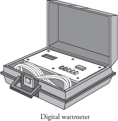
Power is measured in watts, and an instrument that measures watts is known as a wattmeter (Figure 6-29). One watt of power equals the work done in one second, by one volt of potential difference, in moving one coulomb of charge. One coulomb per second is equal to one ampere. Therefore, the power in watts (W) equals the product of amperes (A) times volts (V). The equation is: W = A × V.
FIGURE 6-29 The wattmeter is used to measure watts.
Ohm’s Law Equation Wheel
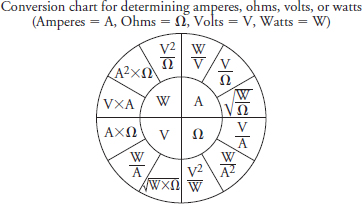
The Ohm’s Law equation wheel in Figure 6-30 shows the equations for calculating any one of the basic factors of electricity. Figure 6-31 shows the cross-reference chart of formulas as used in this text. If you know any two of the factors (V = voltage, A = amperage, R = resistance, W = power), you can calculate a third. To obtain any value in the center of the equation wheel for direct or alternating current, perform the operation indicated in one segment of the adjacent outer circle.
FIGURE 6-30 The Ohm’s Law equation wheel.
FIGURE 6-31 The cross-reference chart of formulas.
Example 1: A 2400-watt heating element is connected to a 240-volt circuit. How many amps does it draw?
When finding amperage, the formula will be found in the Amperes section of the wheel.
Then, solving for amperage:
What is the resistance (ohms)?
Then, solving for resistance:
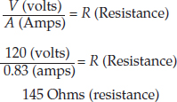
Example 2: What is the resistance of a 100-watt resister if the voltage is 120 volts and the current is 0.83 amps?
When finding resistance, the formula will be found in the Ohms section of the wheel.
Example 3: What is the voltage of a circuit if the resistance of the load is 48 Ohms and current is 5 amps?
A (Amps) × R (Ohms).= V (Volts)
5 (amps) × 48 Ohms = 240 Volts
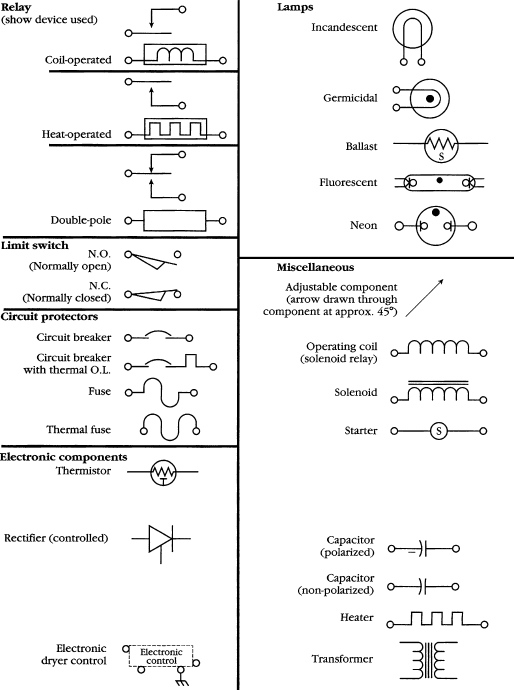
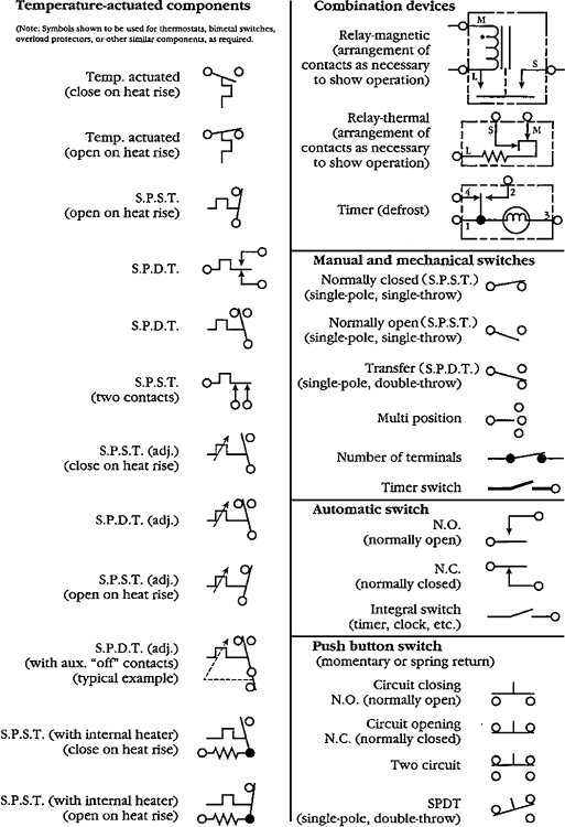
Wiring Diagram Symbols
TABLE 6-1 Wiring Diagram Symbols
TABLE 6-2 Wiring Diagram Symbols
TABLE 6-3 Wiring Diagram Symbols
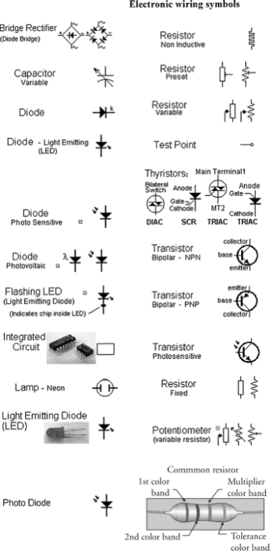
TABLE 6-4 Electronic Wiring Diagram Symbols
Terminal Codes
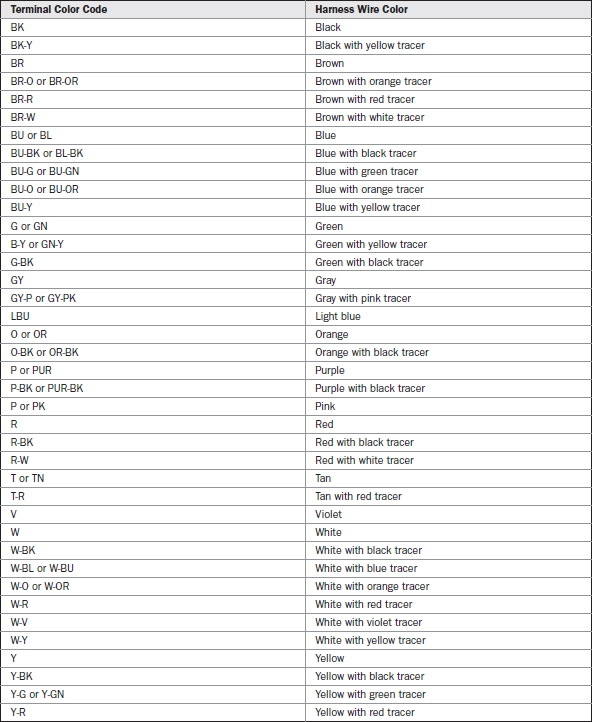
Terminal codes are found on all wiring diagrams. To help you identify the color codes, they are listed in Table 6-5.
Timer Sequence (Esterline) Charts
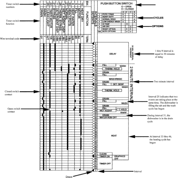
Figure 6-32 represents a sample timer sequence chart. Dishwashers, washers, and dryers have an Esterline Chart, which is also known in the appliance industry as a Timer Sequence Chart, and is part of the technical data sheet along with the wiring schematic, and other helpful information for the technician to use in diagnosing the appliance. This chart indicates the switch contacts that are open or closed at a specific time (interval) during the operating cycle. It is another diagnostic tool that is used in conjunction with the wiring schematic by technicians to assist in diagnosing problems with the appliance.
FIGURE 6-32 A sample timer sequence chart.
The timer sequence chart is divided into the following:
• Overview of all of the columns on the chart.
• Correspondence between the timer dial and the intervals on the timer sequence chart.
• The consumer selects the additional options through the push button switch that will affect the switch contacts opening and closing on the wiring schematic.
• At a certain interval in the operating cycle, the timer sequence chart will show the technician the position of the switch contacts that are open or closed on the wiring schematic.
• The timer sequence chart will indicate which components are energized at any time interval.
Wiring Diagrams
In this section, each of the four examples presented will take you through a step-by-step process in how to read wiring diagrams.
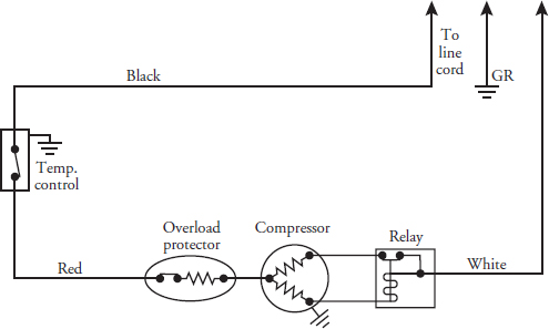
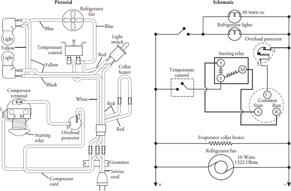
Example 1: Take a look at a simple wiring diagram for a refrigerator (Figure 6-33). Note the black wire on the diagram. This is the wire that goes to the temperature control. The circuit is not energized when the temperature control is in the “off” position. When the temperature control knob is turned to the “on” position (switch contacts closed) and the circuit is energized, current will flow through the temperature control, through the red wire, through the overload protector, through the compressor and the relay, and back through the white wire to the line cord.
FIGURE 6-33 A simple wiring schematic of a refrigerator circuit.
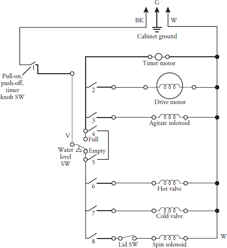
Example 2: In the wiring diagram in Figure 6-34, trace the active circuits with your finger. Note switch number 1. This is the first switch in the line, and it is the main switch that supplies voltage to the timer. No circuits are energized when the timer dial is in the “off” position (as the diagram indicates). When the user selects the wash cycle with a warm wash and turns on the timer, switch contacts 1, 2, 3, 6, and 7 are closed. (Use a pencil to close the switches on the diagram.) Voltage is supplied to the water level switch and to the hot and cold water valves. Warm water is now entering the washing machine tub. When the water level reaches the selected position, the water level switch contacts close from V to number 4, indicating that the water in the tub has reached the selected water level. When the water level switch is in this position, the water is turned off. Voltage is now supplied to the timer motor, drive motor, and the agitate solenoid. The washing machine is now agitating and cleaning the clothes. As the timer advances to the spin cycle, timer switch contacts 2 and 3 open, thus turning off the agitate solenoid and the drive motor. Switch contacts 8 and 2 now close, thus supplying voltage to the drive motor and the spin solenoid. The timer motor advances to the end of the cycle, and timer switch contacts 1, 2, and 8 will open. The washing machine is now off, and no circuits are energized.
FIGURE 6-34 The wiring schematic of an automatic washer circuit.
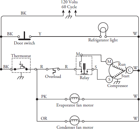
Example 3: The wiring diagram in Figure 6-35 is for a refrigerator. Assume that the thermostat is calling for cooling and the compressor is running. With your finger, trace the active circuits. The thermostat in the wiring diagram for the refrigerator is closed. The evaporator fan motor and the condenser fan motor are running. Voltage is supplied through the overload to the relay. Current is flowing through the relay coil to the compressor-run-winding. Also notice that the door switch is open and the refrigerator light is off. When the temperature in the refrigerator satisfies the thermostat, the thermostat switch contacts will open, thus turning off the compressor, the evaporator fan motor, and the condenser fan motor.
FIGURE 6-35 The wiring schematic of a refrigerator circuit.
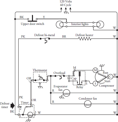
Example 4: The wiring diagram in Figure 6-36 is for a no-frost refrigerator. Note the defrost timer in the lower-left part of the diagram. The defrost timer switch contact is closed to contact 4, the thermostat is calling for cooling, and the compressor is running. Trace the active circuits with your finger. Voltage is supplied to the defrost timer terminal 1. Current will flow through the defrost 2 timer motor to the white wire and then back to the line cord. At the same time, current flows through contact 4 in the defrost timer to the thermostat. At this point, the current passes through the thermostat to a junction and splits in two directions. Current will flow through the temperature control, through the overload protector, through the compressor and the relay, and back through the white wire to the line cord. At the same time, the compressor is running and current will flow through the evaporator and condenser fan motors.
FIGURE 6-36 The wiring schematic of a no-frost refrigerator circuit.
When the defrost timer activates the defrost cycle, the defrost timer switch contact is closed to contact 2, and the compressor is not running. The evaporator and condenser fan motors will also stop running. The current will flow from terminal 2, through the defrost bi-metal, through the defrost heater, and back through the white wire to the line cord. With your finger, trace the active circuits.
Sample Wiring Diagrams
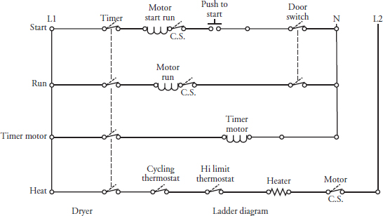
The diagram in Figure 6-37 is known as a ladder diagram. It is a simplified diagram using symbols for parts and control components attached to wires. The timer is represented by a dotted line running vertically through the switch contacts. To read and understand this type of diagram, assume that the complaint is that the dryer is not heating. Look at the section of the diagram marked HEAT. Starting on the left side of the diagram, trace the circuit with your finger. You will notice that L1 goes to one side of the timer switch. As your finger moves from left to right, you will pass over the cycling thermostat, high-limit thermostat, heater, motor centrifugal switch (CS), and on to L2. These are the components that make up the heating circuit. You must also include the motor and the door switch. If the door switch should fail, the motor will not run, thus opening the motor centrifugal switch (CS). If the motor fails, the high-limit thermostat will open, shutting off the heater element. If any of these components fail, the dryer will not dry the clothing.
FIGURE 6-37 A simple ladder diagram.
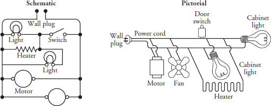
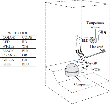
The diagrams in Figure 6-38 and Figure 6-39 illustrate a pictorial diagram and a schematic diagram. The pictorial diagram shows the actual picture of the components, and the schematic diagram uses symbols for the components. Figure 6-40 shows a pictorial diagram of a refrigerator. In this type of diagram, you can see where the components are actually located.
FIGURE 6-38 A pictorial diagram and a schematic diagram. Both show the same components.
FIGURE 6-39 A pictorial diagram and schematic diagram.
FIGURE 6-40 A pictorial diagram of a refrigerator, showing where the components are located.
How to Read the Volt-Ohm-Milliammeter Test Instrument
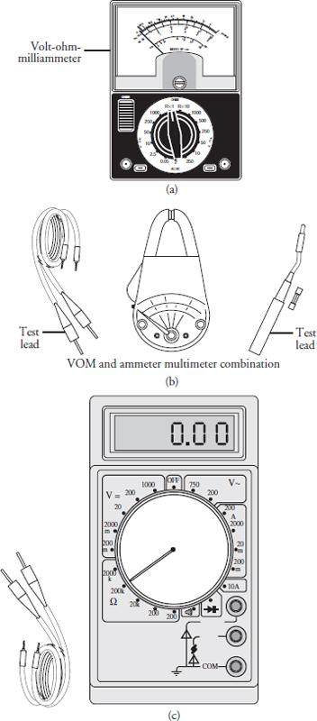
The volt-ohm-milliammeter (VOM) is sometimes called a multimeter because it can perform more than one function. A typical VOM will allow you to measure voltage, resistance, and current:
• Voltage equals electromotive force.
• Resistance equals the amount of resistance holding back the flow of current (measured in ohms).
• Current equals the amount of electricity flowing through a wire or circuit component (measured in amperes). There are many different types and brands of VOMs (Figure 6-41). However, all VOMs are used in the same way to measure voltage, current, or resistance. Most VOMs will have the following:
FIGURE 6-41 (a) Volt-ohm-milliammeter, (b) VOM and ammeter multimeter combination, (c) digital multimeter.
• Test leads These are the wires coming from the meter to the part being tested.
• Meter scales and pointer (or a digital display on a digital meter) These show the amount of whatever value you are measuring.
• Function switch This allows you to select whether you will be measuring AC or DC voltage (volts), current (amps), or resistance (ohms).
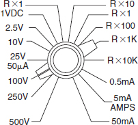
• Range selector switch This allows you to select the range of values to be measured. On many meters, you can select functions and ranges with the one switch (as in the meter pictured in Figure 6-41a and Figure 6-41c).
Measuring Voltage
If you don’t have the right voltage in an appliance or air conditioner, the product won’t function properly. You can find out whether the product is getting the right voltage by measuring the voltage at the wall outlet (receptacle). If an appliance or air conditioner isn’t getting the proper voltage, nothing else you do to fix it will help.
For your safety, before using any test instrument, it is your responsibility as a technician to read and understand the manufacturer’s instructions on how the test instrument operates.
Making the Measurement
Making voltage measurements is easy once you know how to select and read the scales on your meter. When measuring voltage, you should perform the following steps:
• Attach the probes (another term for test leads) to the meter. Plug the black probe into the meter jack marked negative or common. Plug the red probe into the positive outlet.
• Set the function switch to AC VOLTS.
• Select a range that will include the voltage you are about to measure (higher than 125 Vac if you are measuring 120 volts; higher than 230 Vac if you are measuring 220 volts). If you don’t know what voltage to expect, use the highest range, and then switch to a lower range if the voltage is within that amount.
• Touch the tips of the probes to the terminals of the part to be measured.
• Read the scale.
• Decide what the reading means.
Selecting the Scales
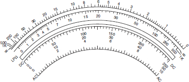
To measure the voltage in appliances and air conditioners, use the AC/DC scales (Figure 6-42). These same scales are used for both AC and DC readings. The numbers on the right side of the AC/DC scales tell you what ranges are available to you. The meter face in Figure 6-43 has three scales for measuring voltage: one is marked 10, another 50, and the third is marked 250. Remember—the scale you read is determined by the position of the range switch.
FIGURE 6-42 An example of scales used on some VOMs.
FIGURE 6-43The meter face of an analog meter.
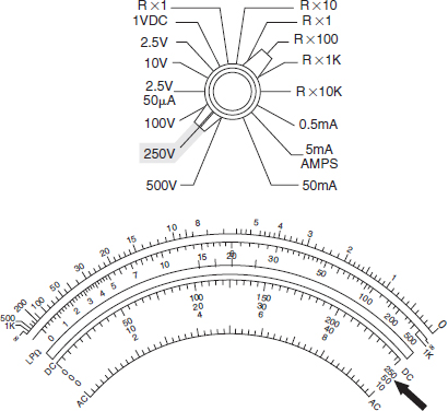
EXAMPLE If the range is set on 250 V, as in Figure 6-44, you read the 0- to 250-V scale.
FIGURE 6-44 The range is set on the 250-V scale.
Reading the AC Voltage Scale
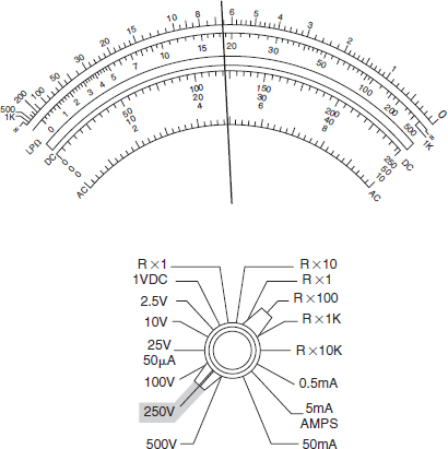
When reading the pointer position, be sure to read the line marked AC (Figure 6-43). The spaces on the voltage scales are always equally divided. When the pointer stops between the marks, just read the value of the nearest mark. In Figure 6-45, the pointer is between 115 and 120 volts on the 250 scale. Read it as 120 volts. With an analog meter, you’re not gaining anything by trying to read the voltage exactly.
FIGURE 6-45 The range is set on the 250-V scale, and the pointer reads 120V.
Measuring Line Voltage
Measuring line voltage is the first, and most important, part of checking out an appliance or air conditioner that does not operate. Line voltage is the voltage coming from the wall outlet. There should be approximately 120 volts AC at the outlet under “no-load” conditions. No-load means that no appliance or air conditioner is connected or that an appliance or air conditioner is connected but it is turned off.
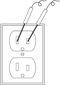
To measure line voltage under no-load conditions at 120 volts (Figure 6-46):
1. Set the meter to measure AC volts.
2. Set the range selector to the range nearest to but higher than 120 volts.
3. Insert either test lead into one slot of an empty wall receptacle.
4. Insert the other test lead into the other slot of the same outlet. (Disregard the ground terminal for this test.) Warning: Do not touch or handle the test leads by the metal portion of the probe. Hold the probe by the plastic grips that are attached to the test leads to avoid electric shock.
5. Read the meter. The reading should be between 115 and 120 volts.
6. When testing for 240 volts, be sure that the range selector is set to the nearest range higher than 240 volts. Note: Most appliances and small BTU-sized air conditioners are rated at 120 volts, but will work on voltages ranging from 110 to 125 volts. If the voltage drops more than 10 percent, the appliance or air conditioner will not operate, and most likely will damage some electrical components if the appliance or air conditioner keeps running.
FIGURE 6-46 Measuring line voltage with no load.
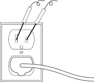
To measure line voltage under load at 120 volts (Figure 6-47):
1. Be sure that the appliance or air conditioner is plugged into one of the receptacles and that the product is turned on.
2. Follow steps 1–5 for no-load conditions, inserting the test leads into the empty receptacle next to the one into which the product is plugged.
3. Under load conditions (appliance or air conditioner is turned on), your reading will be slightly less than under no-load conditions.
4. When testing for 240 volts, be sure that the range selector is set to the nearest range higher than 240 volts. Note: Products with drive motors and compressors, such as automatic washers, dishwashers, trash compactors, refrigerators, air conditioners, and microwaves, should also be tested at the moment of start. If the voltage drops more than 10 percent of the supplied voltage when the motor is started, there is a problem with the electrical supply.
FIGURE 6-47 Measuring line voltage under load.
Testing for Ground and Polarity
When a component is grounded to a chassis, there is no voltage between the two. When a chassis is grounded to the earth, there is no voltage between the chassis and the earth. If there is voltage between a chassis and the earth, it’s dangerous. If you stand on the earth (dirt, concrete slab, etc.) and touch the chassis, electricity will flow through your body. You could injure yourself, or even someone else, and death could occur. It is important to be sure that the electrical outlets in the home from which appliances or air conditioners are powered are correctly wired. That will protect the users from electrical shock.
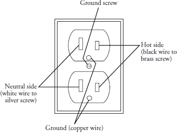
If an outlet is wired “backward” (that is, the black or red “hot wire” is connected to the long slot of the outlet), the appliance or air conditioner connected to that outlet might be unsafe to operate, blow the fuse, or trip the circuit breaker. Appliances and air conditioners with solid-state controls will not function properly if the outlets are wired backward.
To test for ground:
1. First, test for line voltage. (If there is no voltage, you can’t test for ground.)
2. Notice that the receptacle has a longer and a shorter slot (Figure 6-48). If the outlet has been mounted right-side up, the longer slot will be on the left.
FIGURE 6-48 Receptacle identification points.
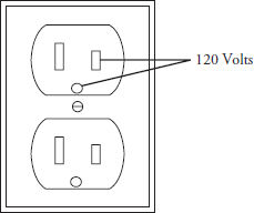
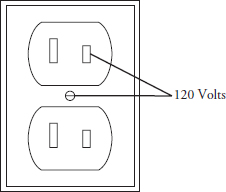
3. Test for voltage between the short slot and the ground receptacle (the round hole), as shown in Figure 6-49. If there is line voltage between these two points, the receptacle is grounded.
FIGURE 6-49 Testing for ground.
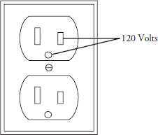
4. If there is no round hole (ground prong receptacle), touch one of your probes to the screw that fastens the coverplate to the outlet (Figure 6-50).
FIGURE 6-50 Testing for ground again.
To test for polarity:
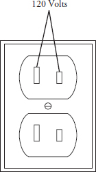
1. Test to be sure that there is line voltage between the longer and shorter slots (Figure 6-51).
FIGURE 6-51 Testing for ground again.
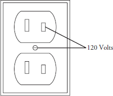
2. Test to be sure that there is line voltage between the short slot and the center screw or the round hole (ground prong receptacle) (Figure 6-50 and Figure 6-51).
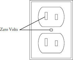
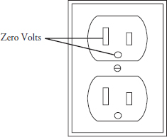
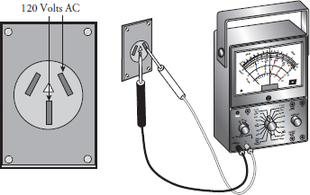
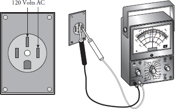
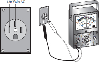
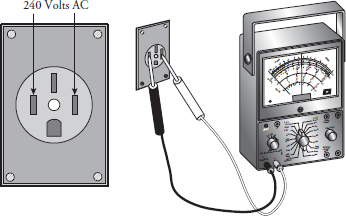
3. Test to be sure that there is no voltage between the longer slot and the center screw or the round hole (Figure 6-52 to Figure 6-55). Note: If these three tests don’t test out this way, the outlet is incorrectly wired and should be corrected by a licensed electrician.
FIGURE 6-52 Testing the polarity of a receptacle.
FIGURE 6-53 Testing the polarity of a receptacle.
FIGURE 6-54 Testing the polarity of a receptacle.
FIGURE 6-55 Testing the polarity of a receptacle.
Measuring 240-Volt Receptacles
Warning: When testing a three-wire or four-wire receptacle for 240 volts, the technician must be extremely careful not to touch or handle the test leads by the metal portion of the probe. Hold the probe by the plastic grips that are attached to the test leads to avoid electric shock. The multimeter must be set on the AC scale to 240 volts or higher. Do not use the ohms scale—the voltage will damage your meter.
Testing a Three-Wire Receptacle for 240 Volts
To test the voltage on a three-wire receptacle with a no-load condition:
1. Select the correct AC range on your multimeter.
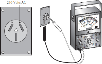
2. Insert the test leads into the receptacle as shown in Figure 6-56. You might have to move the probes around a little to make contact within the receptacle. Check the meter reading—there should be approximately 240 volts. If no voltage is present, check the fuse or circuit breaker.
FIGURE 6-56 Testing the voltage of a three-wire receptacle for 240 volts.
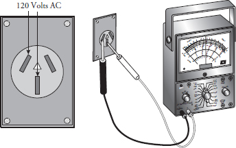
3. Insert the test leads into the receptacle as shown in Figure 6-57. Check the meter reading—there should be approximately 120 volts. If no voltage is present, check the fuse or circuit breaker.
FIGURE 6-57 Testing the voltage of a three-wire receptacle for 120 volts.
4. Next, insert the test leads into the receptacle as shown in Figure 6-58. Check the meter reading—there should be approximately 120 volts. If no voltage is present, check the fuse or circuit breaker.
FIGURE 6-58 Testing the voltage of a three-wire receptacle for 120 volts.
Testing a Four-Wire Receptacle for 240 Volts
The red and black wires attached to the receptacle will each carry 120 volts. The white wire attached to the receptacle is the neutral wire, and the bare wire is the ground wire. This type of receptacle adds additional safety for the consumer and to the product.
To test the voltage on a four-wire receptacle with a no-load condition:
1. Select the correct AC range on your multimeter.
2. Insert the test leads into the receptacle as shown in Figure 6-59. You might have to move the probes around a little to make contact within the receptacle. Check the meter reading—there should be approximately 120 volts. If no voltage is present, check the fuse or circuit breaker.
FIGURE 6-59 Testing the voltage of a four-wire receptacle for 120 volts.
3. Insert the test leads into the receptacle as shown in Figure 6-60. Check the meter reading—there should be approximately 120 volts. If no voltage is present, check the fuse or circuit breaker.
FIGURE 6-60 Testing the voltage of a four-wire receptacle for 120 volts.
4. Next, insert the test leads into the receptacle as shown in Figure 6-61. Check the meter reading—there should be approximately 240 volts. If no voltage is present, check the fuse or circuit breaker.
FIGURE 6-61 Testing the voltage of a four-wire receptacle for 240 volts.
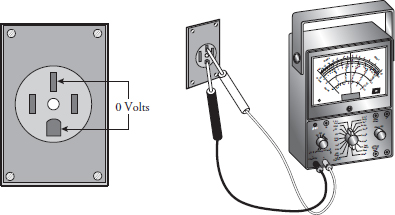
5. Now, insert the test leads as shown in Figure 6-62. The meter should read 0 volts.
FIGURE 6-62 Testing the voltage of a four-wire receptacle for 0 volts.
Measuring Resistance (OHMS)
Electrical appliances and air conditioners need a complete path around which electricity can flow. If there is infinite resistance to the flow of electricity, you have an open circuit or infinite resistance between the two points being measured. When there is a complete path, you have continuity in the circuit. When you test to find out whether there is a break in the path, you say you are making a continuity check.
Continuity checks are made by measuring the amount of resistance there is to the flow of electricity. If there is so much resistance that it is too high to measure (called “infinite”), then you say that the circuit is open (there is no complete path for the electricity to follow). If there is some resistance, it means that there is continuity, but that there is also one (or more) load on the line—a light, a motor, etc. Note: A load is an electrical component that uses electricity to work (for example, a light bulb, a motor, or a heater coil).
If there is no resistance between the two points, it means that the electricity is flowing directly from one point to the other. If the electricity flowed directly from one point to the other by accident or error, then you say you have a short circuit or a “short.”
Setting Up the Meter
Measuring resistance (ohms) is like measuring voltage, except that the measurements are made with the electricity turned off. The steps for measuring ohms are as follows:
1. Attach the leads to the meter. Plug the black lead into the negative outlet and the red lead into the positive outlet.
2. If your meter has a function switch, set the function switch to OHMS.
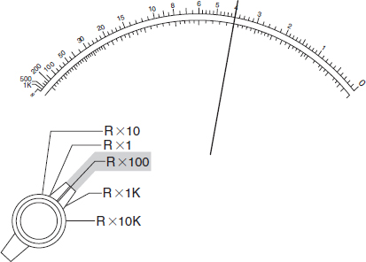
3. If your meter has a range switch, set the range. The range selector switch will have several ranges of resistance (ohms) measurements (Figure 6-63). The ranges are shown like this:
• R × 1: The actual resistance shown on the meter face times 1.
• R × 10: The resistance reading times 10 (add one zero to the reading).
• R × 100: The resistance reading times 100 (add two zeros to the reading).
• R × 1K: The resistance reading times 1000 (add three zeros to the reading).
• R × 10K: The resistance reading times 10,000 (add four zeros to the reading).
4. Set the range so that it is higher than the resistance you expect. If you don’t know what measurement to expect, use the highest setting and adjust downward to a reading of less than 50. The left side of the scale is too crowded for an accurate reading.
5. Zero the meter. You should do this each time you set it. To “zero the meter” means to adjust the pointer so that it reads 0 when the two test leads are touched together. Use the Ohms Adjust knob on the front of the VOM to line up the pointer over the zero on the ohms scale.
6. Attach the test leads to the component you are measuring.
7. Take the measurement. In Figure 6-63, the range selector switch is on R × 100, and the measurement is 400 ohms.
FIGURE 6-63 Testing the voltage of a four-wire receptacle for 0 volts.
Electrical Safety Precautions
Know where and how to turn off the electricity to your appliance or air conditioner—for example: plugs, fuses, circuit breakers, or cartridge fuses. Know their location in the home and label them. When replacing parts or reassembling the appliance or air conditioner, you should always install the wires on their proper terminals according to the wiring diagram. Then check to be sure that the wires are not crossing any sharp areas, are pinched in some way, or are between panels or moving parts that might cause an electrical problem.
These additional safety tips can help you and your family:
• Always use a separate, grounded electrical circuit for each major appliance or air conditioner.
• Never use an extension cord for major appliances.
• If you have to use an extension cord for a room air conditioner, make sure to use one that is properly rated for the size air conditioner installed.
• Be sure that the electricity is off before working on the appliance or air conditioner.
• Never remove the ground wire of a three-prong power cord, or any other ground wires from the appliance or air conditioner.
• Never bypass or alter any appliance or air conditioner switch, component, or feature.
• Replace any damaged, pinched, or frayed wiring that might be discovered when repairing the appliance or air conditioner.
Operating Appliances and Room Air Conditioners on a Generator
There are times when we have to seek alternate sources of electricity to run appliances and room air conditioners. Many people are installing auxiliary power generators as an alternative. In the 2004-2005 hurricane season, my family and neighbors were without electricity for up to three weeks per each hurricane. Luckily, we had a generator to power our home. When I purchased the generator, I had to take into account what appliances I intended to run off it.
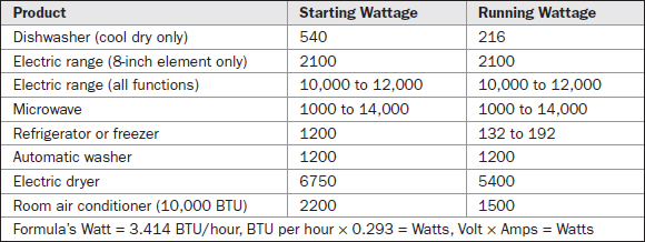
When you consider running lights, appliances, and room air conditioners on a generator, you must calculate how much wattage is needed for each product, including the start-up wattage. In addition, the voltage (120 or 240) and cycles (60) are critical for proper operation of appliances and air conditioners. If the voltage is less than 10 percent of the operating voltage, refrigerators, freezers, and room air conditioners will not operate properly, which might cause damage to the components in the product. Any variation in the cycles could speed up the clocks or slow them down. It is also important when searching for a generator that it has the ability to regulate the voltage and has surge protection for use with appliances and room air conditioners. Table 6-6 provides a guide for the average wattage requirements for some products when choosing the appropriate size generator to purchase.
TABLE 6-6 Wattage Requirement Chart
Flowcharts
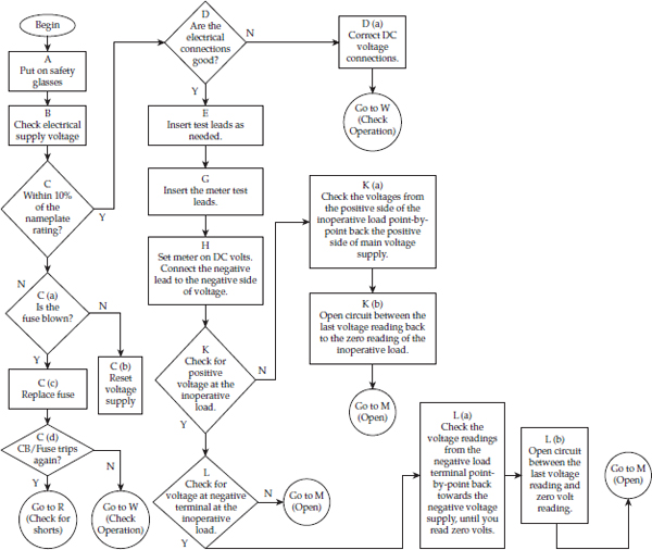
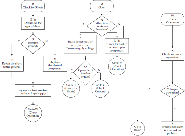
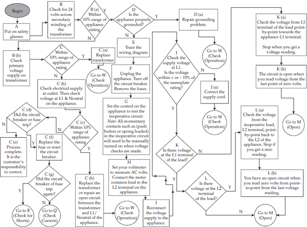
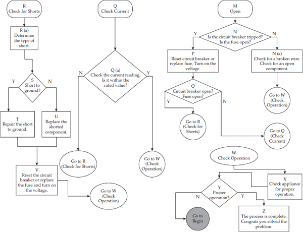
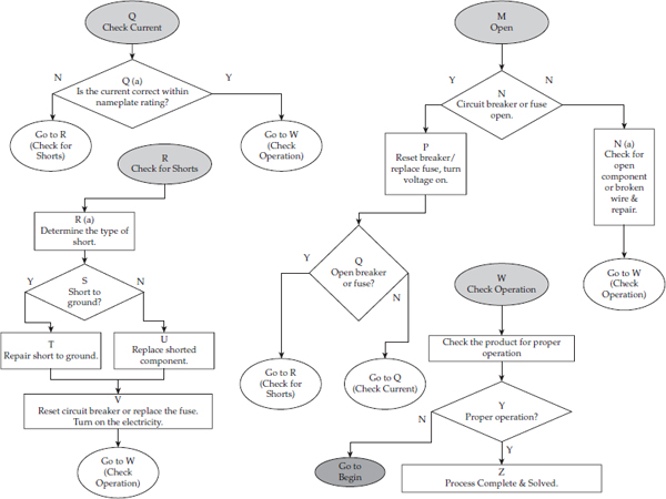
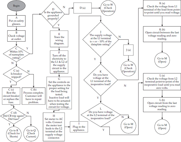
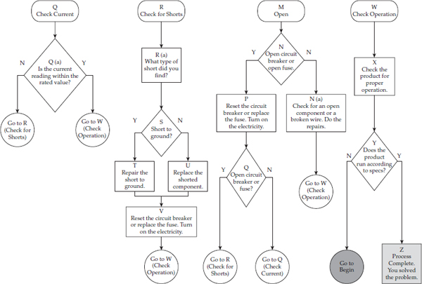
A flowchart is a diagnostic tool that helps the technician to diagnose an appliance or air conditioner. It provides you with a step-by-step process to solve the problem. Choose the flowchart needed, start at the beginning, follow the arrows to the next box, and so on, until you solve the problem. The following are for diagnosing the electrical circuits of a product:
FIGURE 6-64a Direct current diagnostic flowchart.
FIGURE 6-64b Direct current diagnostic flowchart.
FIGURE 6-65a 24-volt AC diagnostic flowchart.
FIGURE 6-65b 24-volt AC diagnostic flowchart.
FIGURE 6-66a 120-volt AC diagnostic flowchart.
FIGURE 6-66b 120-volt AC diagnostic flowchart.
FIGURE 6-67a 240-volt AC diagnostic flowchart.
FIGURE 6-67b 240-volt AC diagnostic flowchart.
