7
CHAPTER
Electronics
When servicing major appliances and air conditioners, you will also encounter electronic parts and/or integrated circuit boards within them. Manufacturers introduced electronic parts for a number of reasons, such as reliability, miniaturization, standardization, and maintainability. Here are some more basic reasons for electronic integrated circuit boards:
• Electronic integrated circuit boards will cost less to produce than their mechanical counterparts.
• You can program the electronic integrated circuit board to save the customer money during operation.
• The customer can choose more programs that come with the component.
• To make the appliance more efficient, the electronic control can use the feedback circuits.
• Electronic integrated circuit board displays are easier to read and set than the old-fashioned mechanical timers.
• During power outages, some electronic integrated circuit boards have a battery backup to keep track of what was programmed into the board, including the time.
• Electronic integrated circuit boards have built-in self-diagnostics and error codes.
When troubleshooting these electronic parts or integrated circuit boards, the technician will determine that an integrated circuit board has failed and will change the entire circuit board rather than repair the electronic components on the board. Although this chapter cannot cover all there is to know about electronics, it provides the basics. With the influx of electronic components into appliances and air conditioners, it is imperative that service technicians be able to troubleshoot them.
In order to troubleshoot electronic circuits, the technician will need the following:
• The technical data sheet or wiring diagram.
• An understanding of the appliance’s or air conditioner’s operation.
• Knowledge of how the controls were set and usage of the product prior to your arrival.
• Knowledge of how to access and use the diagnostic service mode. Each product has a different way to access the service mode.
• An understanding of how to read wiring diagrams and other circuit charts.
In order to properly diagnose a problem in an appliance or air conditioner, you will have to determine if the problem is any or all of the following:
• Electrical
• Mechanical
• Customer related
Before you can replace an electronic component, you must rule out everything else.
Simplified Circuits
When compared to mechanical timers, the electronic integrated circuit board, also known as the electronic control board, has wiring circuits that are more simplified and easier to read. Figure 7-1 shows two wiring strip circuits of a range set on bake. The top circuit illustrates a mechanical timer and a mechanical thermostat. The bottom circuit illustrates the electronic control board. You can see in both strip circuits that the bottom circuit is easier to read and easier to diagnose.
FIGURE 7-1 Wiring strip circuit for a range with the bake mode on. Mechanical components vs. electronic control components.
Electronic Controls
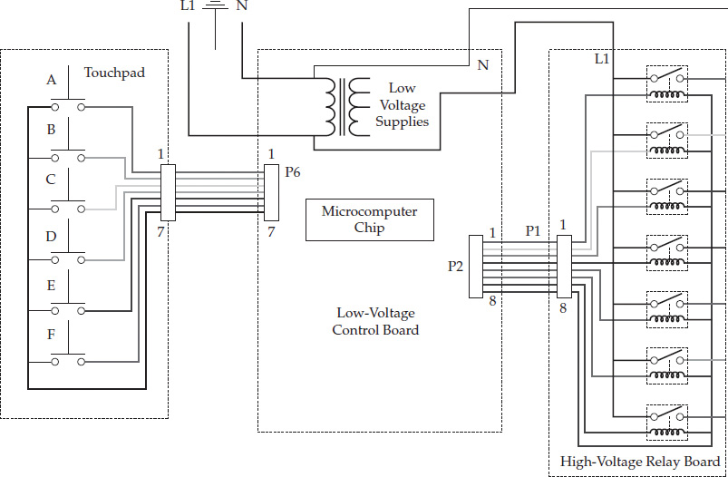
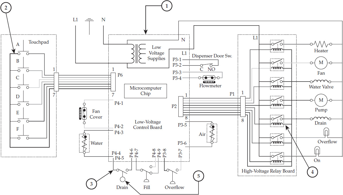
In an appliance or air conditioner, in theory, the electronic control system could use a low-voltage control to run a high-voltage control. There are three main areas in the basic electronic control system (Figure 7-2). These areas are
• The low-voltage control board
• The high-voltage relay board
• The touchpad (customer interface)
FIGURE 7-2 Basic electronic control system.
Low-Voltage Board
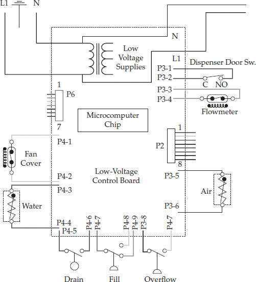
The low-voltage board (Figure 7-3a) consists of the following components:
• Transformer
• Microcomputer chip (the brain)
• Sensor inputs
• Control outputs
• Ribbon connectors
FIGURE 7-3a The low-voltage board, sometimes called the main computer board.
The electronic control board has a 120-volt step-down transformer attached to it. It converts the high voltage to smaller voltages consisting of 24 volts, 10 volts, 5 volts, 3 volts, etc. The smaller voltages will operate the circuits on the control board, including other circuits in the appliance or air conditioner. These other circuits include input from sensors and touchpad circuits. The microcomputer chip on the integrated circuit board is the brain that controls and interprets the inputs and the outputs of the circuit, and decides what components should be operating according to the preprogrammed instructions from the customer.
High-Voltage Relay Board
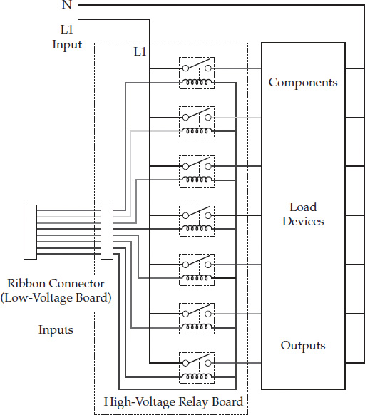
The components and functions of the high-voltage relay board are
• Inputs from the power supply
• The relays
• Component/load outputs
On the high-voltage relay board (Figure 7-3b), there are two different types of inputs:
• The main voltage supply to the relay board, usually 120 volts.
• The control voltage. This is a lower-voltage AC or DC originating from the electronic control board. These lower voltages operate the relay coils, closing the switch contacts, allowing the load to operate. These loads can be motors, water valves, or even heating elements.
FIGURE 7-3bThe high-voltage relay board.
Touchpad (Customer Interface)
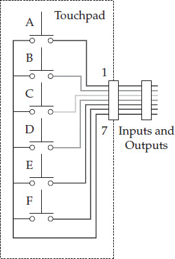
The customer interface, also known as the touchpad (Figure 7-3c), consists of the following items:
• The touchpad itself
• Input
• Output
• Ribbon connector
FIGURE 7-3c The touchpad assembly.
In order for the electronic control board to operate, it must receive inputs (commands) from the touchpad. This device contains switches in a plastic overlay. Every time the customer touches a keypad, it closes a switch temporarily. When the customer touches the keypad, they are programming the microcomputer on the electronic control board by sending low-voltage signals back and forth from the low-voltage board through the ribbon cable that is connected between them.
Three-Board Electronic Control System
A three-board control system consists of the touchpad, the electronic control board, and the relay board (Figure 7-4). Here is how the system operates. When electricity is applied to the circuit, 120 volts goes to the low-voltage transformer (Figure 7-4, circle #1). The transformer will step down (lower) the secondary voltage to be used as a control voltage for the other circuit boards. Also, the transformer supplies different voltage levels to the other areas of the control circuits.
FIGURE 7-4 The three-board electronic control system, consisting of a touchpad, low-voltage board, and the relay board: (1) transformer, (2) touchpad, (3) sensor circuits, (4) relay assigned to a load, (5) sensor circuits still monitoring.
When the touchpad (Figure 7-4, circle #2) is programmed by the customer, a signal is transmitted to the microcomputer chip on the electronic control board. The microcomputer chip will then check with the sensor circuits (Figure 7-4 circle, #3) for feedback. If the microcomputer receives a signal from the sensors that a load needs to be turned on, it will then send a low-voltage supply to the relay coil assigned to that load, a switch will then close (Figure 7-4, circle #4), and the load will operate. On the electronic control board, the microcomputer chip continues to monitor the sensing circuit (Figure 7-4, circle #5); when the preprogrammed instructions are met, the low-voltage supply to the relay coil is turned off, causing the switch to open up and turning off the load.
Troubleshooting Circuits
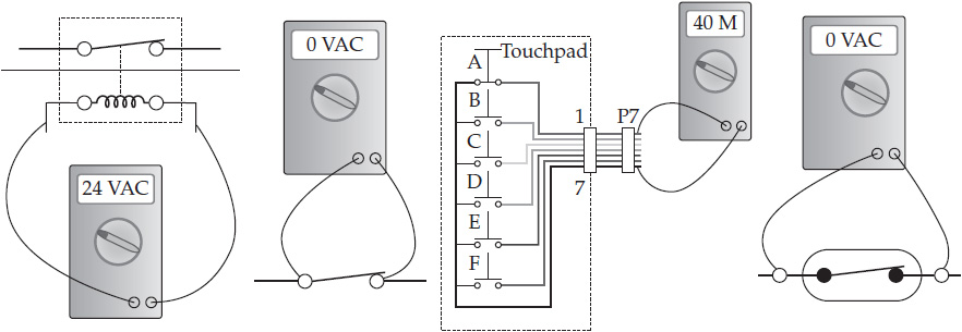
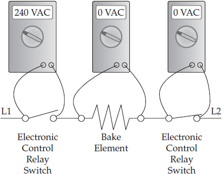
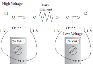
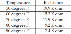
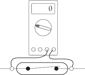
Troubleshooting electronic control system circuitry will depend on the type of method that is used to test the areas of the circuit, which needs to be checked (Figure 7-5). High-voltage circuitry can be tested by using the same procedures as for nonelectronic circuits and components. For example, Figure 7-6 represents a simple range circuit, where voltage testing will be performed. The switches on the electronic control board will be tested the same way as any other standard mechanical switch. The load devices attached to the three-board system will be tested in the same manner as the loads in a mechanical controlled system. The method used to test the low-voltage circuits will depend on what type of circuit is involved. For example, in Figure 7-7, low-voltage checks can be performed on the relay coil if the circuit goes to the high-voltage relay board. How the sensor input circuits are tested will depend on what type of circuit is involved. For example, in Figure 7-8, for a sensor to measure the correct temperature, you will need to perform a resistance check on the sensor. Then you will compare the resistance reading to the corresponding temperature reading on the chart that is on the technical data sheet that comes with the appliance or air conditioner. When the sensor acts as a switch in a circuit (Figure 7-9) you can test the component using resistance readings or voltage checks. The touchpad (Figure 7-10) that programs the microcomputer on the electronic control board is a set of switches. When a keypad is pressed, signals are transmitted. Test the touchpad using resistance checks. In order to do this, you will need the technical data sheet.
FIGURE 7-5 Testing the following components: (1) relay coil, (2) switch, (3) touchpad circuit, (4) sensor circuit.
FIGURE 7-6 A simple range circuit, also known as a strip circuit, for the bake element.
FIGURE 7-7 Testing the low-voltage control circuit on the high-voltage board.
FIGURE 7-8 Temperature-to-resistance chart. For instance, if the thermistor is supposed to be reading 70 degrees Fahrenheit, your ohmmeter reading for the thermistor should be 11.9 k-ohms.
FIGURE 7-9This is the symbol for a sensor that acts like a switch.
FIGURE 7-10 Using the ohmmeter to test the keypad switches on the touchpad assembly.
Two-Board Electronic Control System
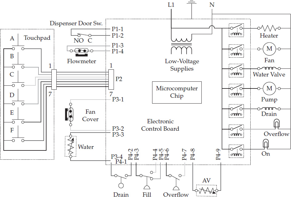
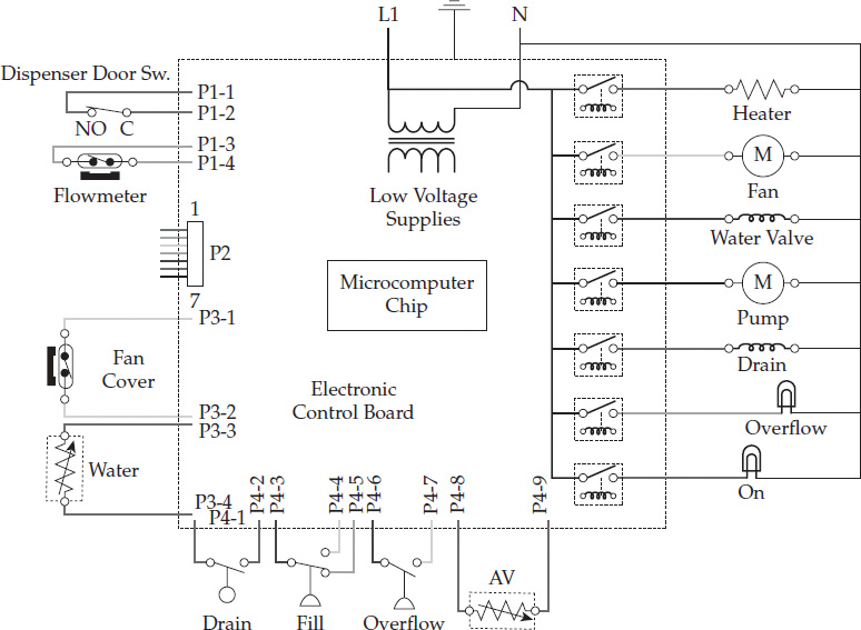
Some manufacturers’ products use a two-board control system (Figure 7-11) instead of a three-board control system. The two types of control systems may be different, but the theory of operation is the same. They simply combine some of the components on a single board, which drives down the production cost. The components forming the low-voltage control board and the high-voltage relay board are combined into one board (Figures 7-12 and 7-13), and include the following:
• Low-voltage transformer
• Microcomputer chip
• Inputs from the sensors
• Inputs from the power supply
• Outputs from the loads
• Relays
FIGURE 7-11 A two-board electronic control system.
FIGURE 7-12 The low-voltage board combined with the relay board to make one combination board.
FIGURE 7-13 Another type of two-board electronic control system. This combination board includes a touchpad assembly.
All of the sensors and load devices operate the same on both systems. The second board will be the touchpad.
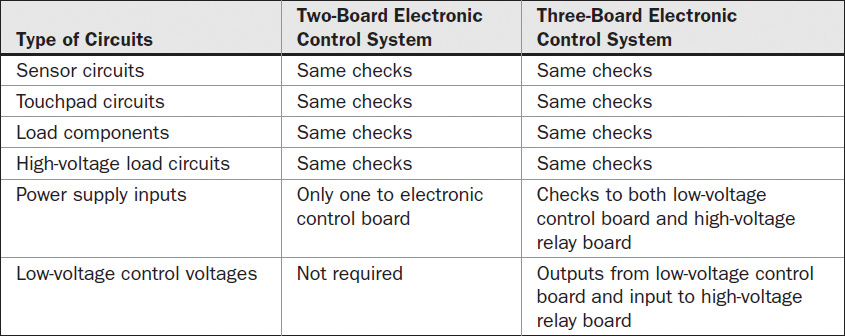
When troubleshooting the two- or the three-board electronic control systems, there are fewer test points (see Table 7-1).
TABLE 7-1 Compare the Testing of a Two-Board Electronic Control System vs. Three-Board Electronic Control System
Motor Board Electronic Control System
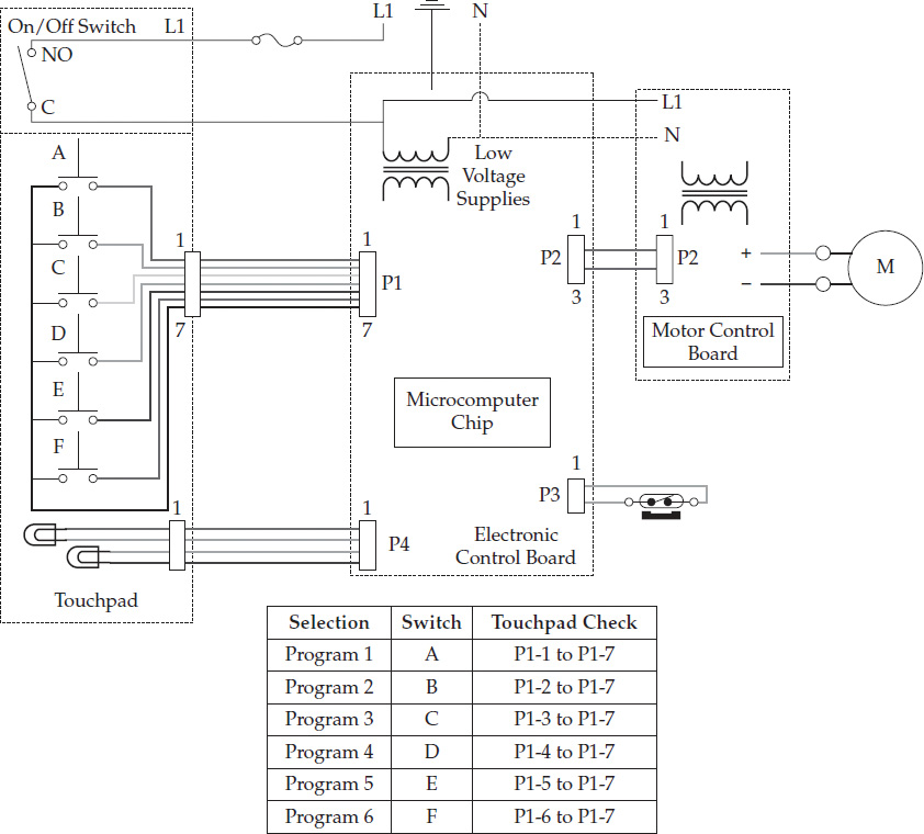
If you take a motor control board system and add it to a two-board control system, you will have another version of a three-board electronic control system. The motor control board is used to run a variable-speed motor. This type of control system (Figure 7-14) incorporates a touchpad, an electronic control board, and a sensor circuit.
FIGURE 7-14 Another version of a two-board electronic control system that incorporates a motor control board.
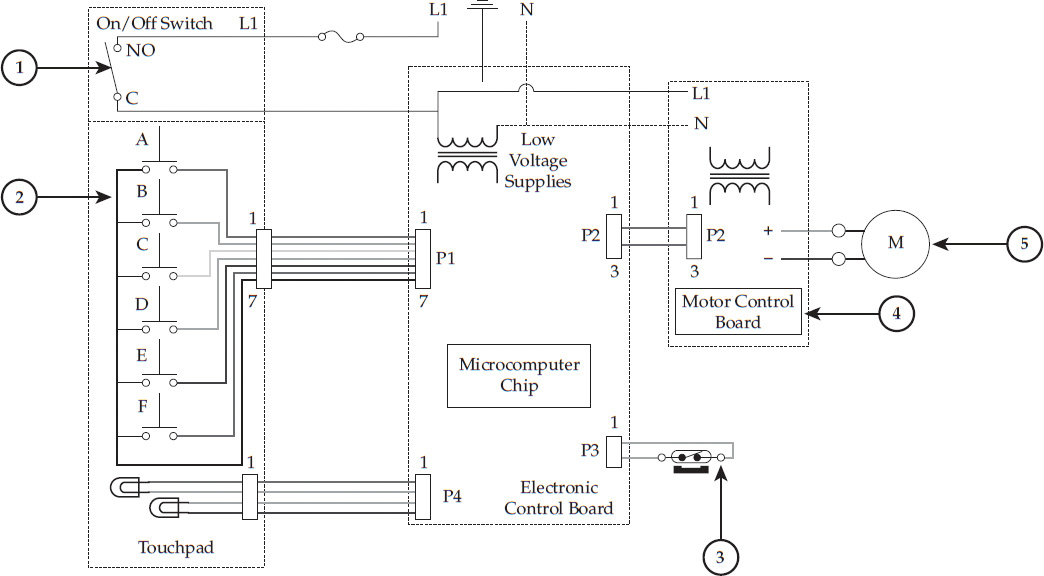
Figure 7-15 illustrates how voltage flows through one type of a variation of a two-board electronic control system with a motor control board. When voltage is applied to the product and turned on, voltage is supplied to the transformer (Figure 7-15, circle #1) on the electronic control board, and at the same time voltage is supplied to the motor control board (Figure 7-15, circle #4). The microchip on the electronic control board receives a signal from the touchpad (Figure 7-15, circle #2). The microchip monitors the reed switch in the sensor circuit (Figure 7-15, circle #3). In order to turn on the motor (Figure 7-15, circle #5), the microchip sends a signal to the motor control board (Figure 7-15, circle #4). The microchip on the electronic control board monitors the sensor circuit and tells the motor control board to adjust the motor speed to go faster or slower. The motor control board will adjust the supply voltage to the motor according to the type of signal received from the microchip. There are many different types of motor control systems in use and manufactured according to the appliance, brand, and model. Each control system has its own diagnostic codes built into the microchip and troubleshooting procedures. These service procedures and diagnostic codes can be found on the technical data sheet that is attached to all appliances and air conditioners.
FIGURE 7-15 Two-board electronic control system with a motor control board: (1) on/off switch, (2) touchpad, (3) sensor circuit, (4) motor control board, (5) the motor (load).
In many of these control systems, the signal voltage and the voltage supplied to the motor will not only vary in voltage, but also in frequency. The frequency is the number of complete cycles per second of alternating current. These voltages and frequencies will also vary according to the load placed on the product. You cannot successfully measure these voltages and frequencies using a digital meter. When you read through the technical data sheet, it will provide you with the necessary information needed to take resistance measurements, and other techniques used for troubleshooting the problem for each model.
There are many troubleshooting checkpoints in an electronic control system using a motor control board for the service technician to test. There are voltage inputs and outputs to both the electronic control board and to the motor control board. Some other checkpoints are as follows:
• High-voltage circuit
• 120-volt source circuits
• The fuse
• The on/off switch
• Electronic control/signal circuits
• The connection on the electronic control board for the wiring between the electronic control board
• The connection on the motor control board for the wiring between the electronic control board and the motor control board
• Motor/motor control circuits
• The connection on the motor control board for the wiring between the electronic control board and the motor control board
• The motor and the connection on the motor for the wiring between the motor control board and the motor
• Touchpad
• The line side and neutral side wiring to a switch
• The wiring for the on/off light
• Sensor
• The reed switch (check for continuity)
• The wiring to and from the reed switch
Resistors
A resistor, when installed into an electrical circuit, will add resistance, which will produce a specific voltage drop, or a reduction in current. Resistors can be either fixed or variable. The most common problem found with resistors when testing them with a milliammeter is that they read as open (infinite ohms). To determine the resistance value in ohms of a resistor, you have to isolate it from the circuit and then use your ohmmeter to read its value. On larger resistors, the resistance value is stamped on the body of the resistor.
A visual inspection of the resistor should also be performed to rule out any physical flaws in the resistor and the surrounding components. If you touch a resistor and it begins to flake apart, most likely it is bad and it needs to be replaced. If the technician smells a burning smell coming from the resistor, most likely this component is bad and it must be replaced.
Resistance Color Bands
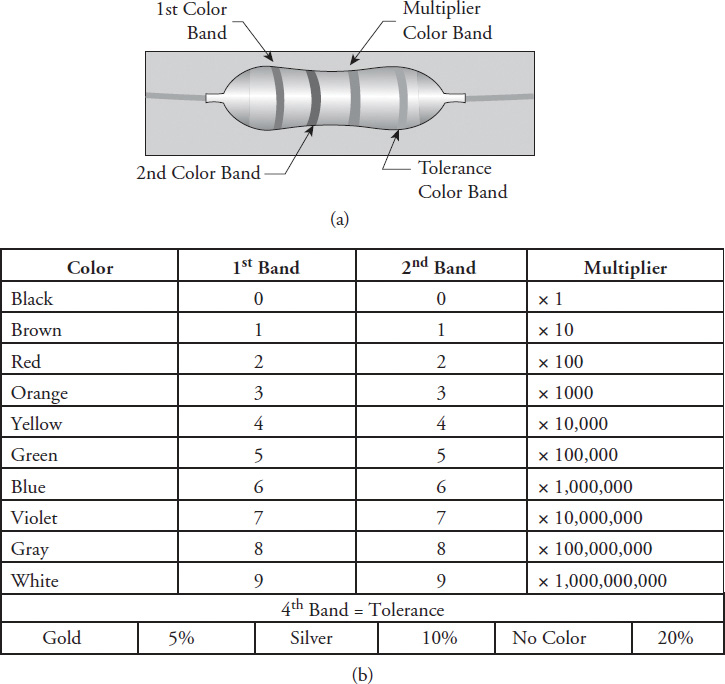
Because of their size, most axial resistors (Figure 7-16a) are color coded, usually with four bands to indicate their resistance value. Reading the resistor bands from left to right, the first band closest to the end indicates the first numerical digit of resistance. The second band indicates the next numerical digit of resistance, and the third band indicates the numerical multiplier in zeros. The fourth band on a resistor is the resistance tolerance measured in a percentage (Figure 7-16b). For example, let’s say the color bands are brown, red, orange, and silver:
Brown = 1
Red = 2
Orange = 1000
Silver = + or −10 percent
FIGURE 7-16 (a) A common resistor. (b) Resistor color-code chart.
The resistor is rated at 12,000 ohms with a ±10 percent tolerance. The tolerance is the safe operating percentage difference of the color-coded resistance value. For instance, a 12,000-ohm resistor with a 10 percent tolerance will operate safely at 10 percent below or 10 percent above the 12,000-ohm valve.
Thermistor
Thermistors are constructed from a semiconductor material with a specified temperature range. This electronic device exhibits a change in resistance with a change in temperature. There are two types of thermistors: negative temperature coefficient (NTC) and positive temperature coefficient (PTC), with the most common being NTC. The resistance of the NTC thermistor decreases with an increase in temperature, whereas the resistance of the PTC thermistor increases with an increase in temperature. There are many applications for thermistors, including their use as temperature sensors, resettable fuses, current limiters, and power indicators. They are also used in applications where interchangeability without recalibration is required.
One type of test performed on thermistors to check if they are good or bad is the resistance-versus-temperature test. To perform this test, the technician will have to locate the technical data sheet that comes with the appliance. The data sheet will provide the resistance (ohms) value at the test temperature listed. Another way to test the thermistor is by testing it with an ohmmeter for an open or a short.
Diodes
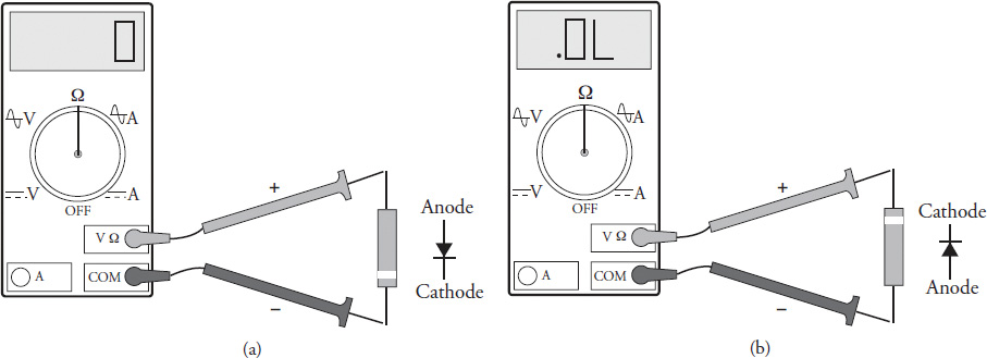
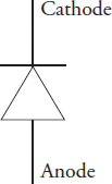
A diode is an electrical device that allows current to flow in one direction only. If you connect a positive voltage to the anode (positive side of the diode) and a negative voltage to the cathode side (negative side of the diode), the diode becomes forward-biased (Figure 7-17a). When the diode is forward-biased, current will flow. When a positive voltage is connected to the cathode (negative side of the diode) and a negative voltage is connected to the anode (positive side of the diode), the diode becomes reverse-biased (Figure 7-17b). Then the diode will not allow current to flow. A diode may be thought of as a switch “closed” when forward-biased and “open” when reverse-biased. There are many types of uses for diodes besides rectification. These include capacitance that varies with the amount of voltage applied to the diode and photoelectric effects. The wiring diagram symbol for a diode is shown in Figure 7-18.
FIGURE 7-17 (a) When testing the diode with an ohmmeter, the forward bias indicates zero ohms of resistance. (b) When testing the diode with an ohmmeter, the reversed bias indicates infinite resistance.
FIGURE 7-18 The wiring diagram symbol for a diode.
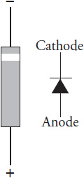
When a diode is connected in a circuit, there must be a means to identify the cathode and the anode (Figure 7-19). Diodes are manufactured in different case styles. On large diodes, there is a diode symbol stamped on the side to Cathode indicate to the technician the cathode and anode. On smaller diodes, there is a band around one end to identify the cathode.
FIGURE 7-19 The band closest to the end of the diode is the cathode (−), and the other end is known as the anode (+).
Testing a Diode
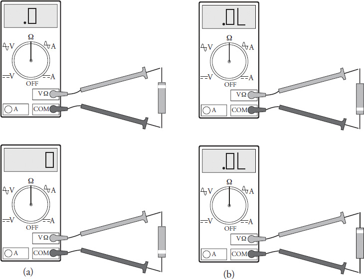
A diode can be tested with an ohmmeter. To test a diode, you must first disconnect one side of the diode to isolate it from the remainder of the circuit. Set your ohmmeter to the ohms scale, and connect the leads to the diode. The meter may or may not read continuity. Then reverse the leads on the diode and check for continuity. You should read continuity in one Cathode direction only. If continuity is not indicated in either direction, the diode is open (Figure 7-20a). If continuity is indicated in both directions, the diode is shorted (Figure 7-20b).
FIGURE 7-20 (a) The ohmmeter indicates no continuity in either direction. The diode is open. (b) The ohmmeter reads continuity in both directions, indicating a shorted diode.
With some microwave oven high-voltage diodes, you will not be able to read continuity in any direction. Not all multimeters can perform this function. You will then attach a 9-volt battery in series with the diode (removed from the microwave oven circuit) and take voltage readings. Read the voltage through the diode in one direction, and then reverse the meter leads, and you should not have a voltage reading in the other direction.
Bridge Rectifier
The bridge rectifier (Figure 7-21) consists of four diodes connected together in a bridge configuration on the circuit board. On electronic control boards, a bridge rectifier is used to convert alternating current into direct current for the low-voltage circuitry.
FIGURE 7-21 A bridge rectifier circuit converting AC to DC.
The technician cannot test the bridge rectifier directly because it is wired directly into the circuitry on the integrated circuit board. You can only test the AC input voltage and DC output voltages. If you’re reading on your voltmeter AC input voltage to the electronic board and no DC output voltage from the board, the board is bad and will need to be replaced. If you’re reading on your voltmeter no AC input voltage and no DC output voltage on the electronic board, check the AC voltage supply to the board. If you’re reading on your voltmeter AC voltage input and DC voltage output on the electronic board and the load is not operating, check the load and the connecting wiring from the load to the relay on the circuit board.
Triac
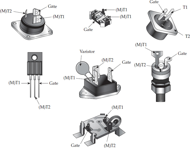
A triac (Figure 7-22) is a three-terminal electronic device that is similar to a diode, except that it allows current to flow in both directions, as with alternating current. There is no anode or cathode in the triac, and it acts as a high-voltage switch on an electronic control board that will turn loads on or off in the circuit. A signal pulse to the gate lead on the triac will trigger the current to flow through the device. The gate loses all control of the triac until the current falls below the manufacturer’s specifications. A triac can supply more or less power to a load depending on the trigger point. They are available with current ratings up to 40 amps and voltage ratings up to 600 volts.
FIGURE 7-22 Various types of microwave oven triacs.
Testing a Triac
Care must be taken if you are testing a triac in a circuit. In a microwave, for example, unplug the appliance and discharge the capacitor. Locate the triac (Figure 7-22) within the circuitry and identify the triac terminals. The three terminals are generally designated as G (Gate), T1, and T2. Do the testing as follows:
• Remove the wires from the triac terminals.
• Set your multimeter on the ohms scale.
• Measure from the T1 to the G (gate) terminal, note the meter reading, then reverse the leads and note the meter reading again.
• The reading in each measurement should be between 10 and 200 ohms, depending on the make and model.
• Next, measure each of the following readings; you should read infinity:
(a) From T1 to T2
(b) From T2 to G (gate)
(c) From each terminal to chassis ground
NOTE These readings are approximate and may vary from manufacturer to manufacturer, but generally speaking, any results that are significantly different would indicate a defective triac.
There is a second test. Turn on the triac in the following manner:
• Remove the wires from the triac terminals.
• Set your multimeter on the ohms scale.
• Attach your negative lead from your meter to the T1 terminal and the positive lead to the T2 terminal.
• Using a screwdriver, create a momentary short between the T2 terminal and the G (gate) terminal. This action should turn on the triac, and the meter reading will between 15 and 50 ohms.
• Next, disconnect one of the meter leads and then reconnect it to the terminal. The meter reading should indicate infinity.
• Finally, reverse the meter test leads and repeat the tests. The results should be the same.
NOTE Any abnormal tests would suggest a defective triac.
Transistor
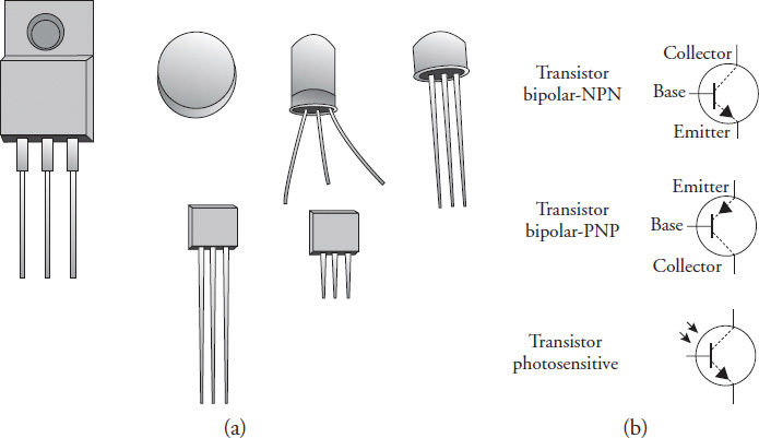
A transistor is a three-element, electronic, solid-state component that is used in a circuit to control the flow of current or voltage. It opens and closes a circuit just like a switch (Figure 7-23a). Other uses for transistors include amplification and oscillation. Transistors are located on circuit boards. Figure 7-23b indicates the wiring diagram symbol for a transistor.
FIGURE 7-23 (a) A sample of the various types of transistors used in circuits. (b) The wiring symbol for an NPN, PNP, and photosensitive transistor.
Integrated Circuits and Circuit Boards
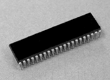
An integrated circuit (IC), shown in Figure 7-24, is a miniature electric circuit consisting of transistors, diodes, resistors, capacitors, and all the connecting wiring—all of it manufactured on a single semiconductor chip. Integrated circuits are found in products like computers, televisions, cell phones, and major appliances and air conditioners. IC chips are not repairable.
FIGURE 7-24 An integrated circuit (IC) chip.
A printed circuit board (PCB) is a layout of conductive pathways (an electric circuit) secured to a board. Electronic components are soldered on to the board for a particular function(s) within an appliance or air conditioner. Only a small percentage of printed circuit boards are repairable. The remaining percentage of PCBs is replaced with new boards.
LED Multiple Segment Displays
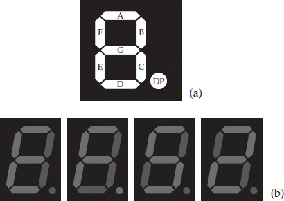
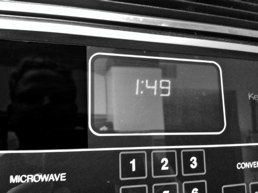
LED segment displays are available in 7, 9, 14, and 16 segment displays (Figure 7-25). Each segment will light up to produce an alphanumeric character. Applications today include displays fitted to ranges, microwaves, automatic washers, automatic dryers, dishwashers, refrigerators, and air conditioners (Figure 7-26). Light-emitting diodes (LEDs) are a semiconductor light source, and they are available in a variety of shapes, sizes, and colors.
FIGURE 7-25 (a) A seven-segment LED display.
(b) Alphanumeric characters.
(c) An LED. (d) and
(e) 16-segment LED displays used on major appliances and A/Cs. (f) Light-emitting diodes (LEDs) are a semiconductor light source.
FIGURE 7-26 An LED display in a microwave oven. It tells a customer the time of day and how much time is left to cook the food.
LEDs are used as a lamp indicator in ranges and ovens. They are used as lamps in other products also. The LED was first introduced for electronics in 1962.
Electrostatic Discharge
The electronic parts in an appliance or air conditioner are sensitive to electrostatic discharge (ESD). An example of electrostatic discharge occurs when you rub your feet on a carpet and then touch a metal doorknob. The little spark that you generated by touching the metal doorknob is ESD. This type of electrostatic discharge will damage the electronics in the appliance or air conditioner at the microscopic level. When servicing an appliance or air conditioner or installing a new electronic part, ESD may cause failure in the future due to stress from these occurrences.
To prevent ESD from damaging expensive electronic components, follow these steps:
• Turn off the electricity to the appliance or air conditioner before servicing any electronic component.
• Before servicing the electronics in an appliance or air conditioner, discharge the static electricity from your body by touching your finger repeatedly to an unpainted surface on the appliance or air conditioner. Another way to discharge the static electricity from your body is to touch your finger repeatedly to the green ground connection on that product.
• The safest way to prevent ESD is to wear an antistatic wrist strap.
• When replacing a defective electronic part with a new one, touch the antistatic package that the part comes in to the unpainted surface of the appliance or air conditioner, or to the green ground connection of the appliance or air conditioner.
• Always avoid touching the electronic parts or metal contacts on an integrated board.
• Always handle integrated boards by the edges.


