8
CHAPTER
Gas
As a technician or novice servicer, this chapter on gas is very important to the safety and technical knowledge that is needed to repair major gas appliances. In addition, consumers should be knowledgeable about safety procedures and basic characteristics of natural and liquefied petroleum gas (LP or LPG). Any person who cannot use basic tools or follow written instructions should not attempt to install, maintain, or repair gas appliances.
If you do not fully understand the procedures in this chapter, or if you doubt your ability to complete the task on your gas appliance, please call your service manager.
Currently, gas is used in millions of homes for heating, cooling, cooking, drying laundry, and water heating. Understanding gas theory, gas conversion, ignition systems, and the different types of gases used is something that every technician needs in his arsenal to service gas appliances. In addition, the technician needs to understand two other important elements when servicing gas appliances: combustion and ventilation. Some appliances use only gas as the main fuel, while others use gas and electricity. Although this chapter cannot cover all there is to know about gas, it provides the basics.
Gas Safety
The following are a few safety tips to help you in handling major gas appliances in your home:
• Always follow the manufacturer’s use and care manual for the gas appliance.
• Always keep combustible products away from gas appliances.
• Keep your gas appliance clean from soot, grease, and food spillages.
• Teach your children not to play near or with gas appliances.
• Always have a fire extinguisher nearby just in case of mishaps that might lead to a fire.
• Have a smoke detector and a carbon monoxide detector installed in the home, and check the batteries yearly.
• Never use a gas range to heat the home.
• Make sure that gas appliances have proper venting according to the manufacturers’ recommendations.
Types of Gas
The two most common gases that are used in homes today are natural gas and liquefied petroleum gas (LP or LPG). Gas is a form of chemical energy, and when it is converted by combustion, it becomes heat energy. This type of heat energy is used for cooking, drying, heating, cooling, and lighting.
Natural Gas
Natural gas is a naturally occurring product made up of hydrocarbon and non-hydrocarbon gases. The main ingredient found in natural gas is methane (70 to 90 percent), with the remainder of the ingredients being nitrogen, ethane, butane, carbon dioxide, oxygen, hydrogen sulphide, and propane. These gases are located beneath the earth and can be removed through constructed wells. Another method for producing and harvesting natural gas is through landfills. The methane gas that is produced by the decomposition of materials can be harvested and added to the natural gas supply.
The heating value of natural gas is between 900 and 1200 BTUs per cubic foot. The air we breathe has a specific gravity of 1.00, and natural gas is lighter than air, with a specific gravity varying from 0.58 to 0.79. Natural gases are odorless and colorless—gas companies add an odor agent to warn for leaks.
The pressure of natural gas that is supplied to a residence will vary, between a 5- and 9-inch water column. A gas pressure regulator that is connected to the appliance will further reduce the pressure. For example, on some gas ranges the pressure will be reduced to a 4-inch water column, while on other models the pressure might be a 6-inch water column. On some water heaters manufactured today, the pressure is between a 4- and 7-inch water column. To determine the correct pressure rating, the technician must refer to the manufacturer’s specifications or the installation instructions for that product.
Liquefied Petroleum Gas
Liquefied petroleum gas (LP or LPG) is obtained from natural gas sources or as a by-product of refining oil. LP gas for domestic use is usually propane, butane, or a mixture of the two. This type of gas is compressed and stored in storage tanks under pressure in a liquid state at approximately 250 pounds per square inch. The pressure in an LP tank will vary according to the surrounding temperatures and altitude. LP gas tanks can be transported to areas that are not supplied by natural gas supply lines.
The heating value of propane gas is 2500 BTUs per cubic foot, with a specific gravity of 1.53. The heating value of butane is much higher—about 3200 BTUs per cubic foot, with a specific gravity of 2.0. Liquefied petroleum gas is heavier than air and will accumulate in low-lying areas on the floor, in an enclosure, or in pockets beneath the ground, creating a hazard if it encounters an open flame. As mentioned, these gases are odorless and colorless, and gas companies add an odor agent to warn of leaks.
LP or LPG gas pressure for residential appliances, as established by the gas industry, will be between a 9- and 11-inch water column. To determine the correct pressure rating, the technician must refer to the manufacturer’s specifications or the installation instructions for that product.
Combustion
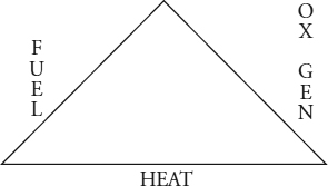
Combustion is a rapid chemical reaction (burning) of LP or natural gas and air to produce heat energy and light. To sustain combustion in a gas appliance, an ignition source—such as that produced by a flame or by electrical means—is used to ignite the gas vapors. Three elements are needed to produce a flame when burning gas vapors: fuel, heat, and oxygen. If any one element is missing, flame or burning of gas vapors will not exist (Figure 8-1).
FIGURE 8-1 The combustion triangle.
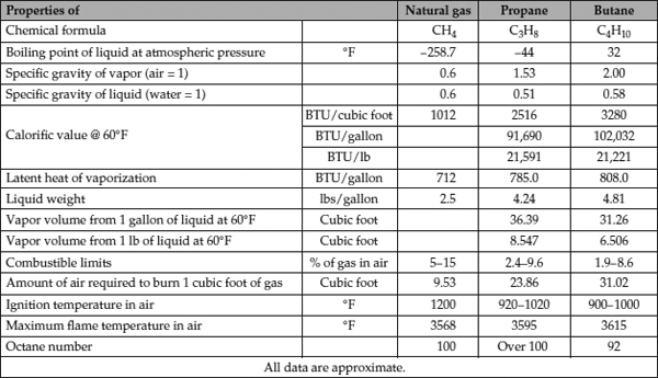
It takes 1 cubic foot of gas mixed with 10 cubic feet of air to have complete combustion of natural gas. The process produces approximately 11 cubic feet of combustion product, consisting of approximately 2 cubic feet of water vapor, 1 cubic foot of carbon dioxide, 8 cubic feet of nitrogen, and the excess air from the gas appliance. These combustion products must be properly vented or discharged safely from the gas appliance.
It takes 1 cubic foot of gas mixed with 24 cubic feet of air for complete combustion to happen with propane gas. The process produces approximately 25 cubic feet of combustion product. With butane gas, it takes 1 cubic foot of gas mixed with 31 cubic feet of air and produces 32 cubic feet of combustion product (Figure 8-2). With the proper mixture of air, gas, and flame, complete combustion will take place. The combustion product that is produced from complete combustion will be carbon dioxide and water vapor.
FIGURE 8-2 Properties of utility gases.
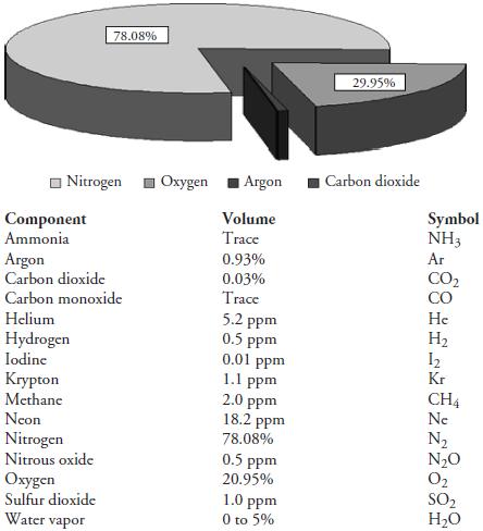
Inadequate venting of a gas appliance will restrict the flow of air into the gas appliance. This lack of proper ventilation will reduce the amount of oxygen within the air for complete combustion to occur. The air that we breathe is a mixture of gases containing nitrogen, oxygen, argon, carbon dioxide, water vapor, and other trace gases (Figure 8-3). Incomplete combustion will cause the reduction of oxygen levels in the air supply within a room. Proper ventilation—adequate fresh air into the room—is important and cannot be stressed enough for the proper operation of a gas appliance, as well as for the safety of human life within the home.
FIGURE 8-3 Composition of air. The air we breathe is made up of 99.99 percent of nitrogen, oxygen, carbon dioxide, and argon.
Carbon Monoxide
Carbon monoxide (CO) is a toxic gas that can cause death if inhaled in copious amounts. It is odorless, colorless, and has no taste. The human body cannot detect carbon monoxide with its senses. When carbon monoxide is inhaled, it is absorbed into the bloodstream and stays there longer, preventing oxygenated blood from performing its job in the body. Two factors affect the amount of carbon monoxide absorbed into the bloodstream: the amount of carbon monoxide in a room and the length of exposure. Lower levels of CO inhalation can cause flu-like symptoms, including headaches, dizziness, disorientation, fatigue, and nausea. Other exposure effects can vary depending on the age and health of the individual.
Carbon monoxide in homes without gas appliances varies between 0.5 to 5 parts per million (ppm). CO levels in homes with properly maintained gas appliances will vary from 5 to 15 parts per million. For those gas appliances that are not maintained properly, carbon monoxide levels may be 30 ppm or even higher.
Testing for Carbon Monoxide
Consumer products for detecting carbon monoxide in a home have been on the market for years. Carbon monoxide detectors should have an alarm that alerts consumers before they are exposed to hazardous levels of carbon monoxide. In order to prevent false alarms, CO detectors must be able to distinguish carbon monoxide gases from other types of gases, such as butane, heptane, alcohol, methane, and ethyl acetate. Two manufacturers that you can visit on the Internet to view the different types of carbon monoxide detectors available are www.kidde.com and www.firstalert.com.
Technicians who test for carbon monoxide use a special handheld meter to check the levels of carbon monoxide in a room or home. For a handheld carbon monoxide test meter, visit www.fluke.com.
When to check for carbon monoxide in a home:
• When the consumer complains of headaches or nausea
• Houseplants are dying
• Unknown chronic odors from unknown sources
• Condensation on cool surfaces that might lead to flue gas products in the home
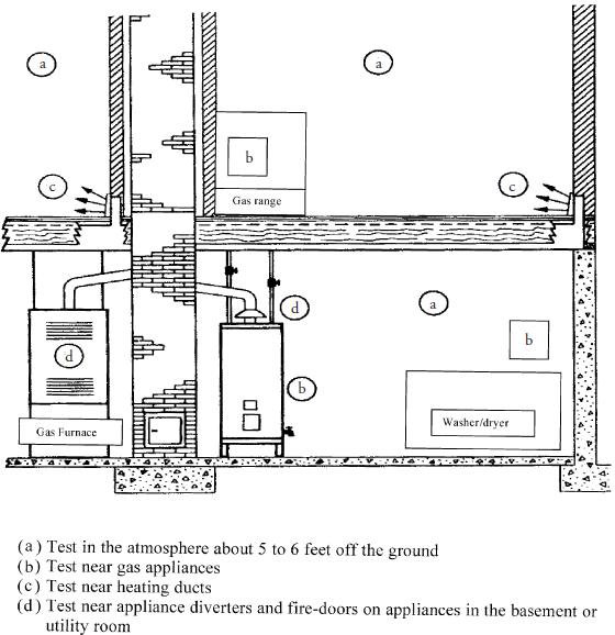
Figure 8-4 illustrates the locations in a home to test for carbon monoxide gas. These tests should be conducted near gas appliances, gas heating systems, heating ducts, and the atmosphere in a room, approximately 6 feet above the floor.
FIGURE 8-4 Typical test locations for carbon monoxide.
When testing for CO in a gas appliance that has not been running for a while, you should follow these steps:
1. Test the air near the appliance and the surrounding air in the room before you turn on the appliance.
2. Test the air after you turn on the appliance.
3. Test the air near the appliance after the appliance has been running for 15 minutes.
Flue Gases
Flue gases are the by-products of combustion that are exhausted through a chimney or flue to the outside of the home. These gases consist of the following:
• Nitrogen (colorless, odorless, and tasteless) The air we breathe is made up of 79 percent nitrogen.
• Carbon dioxide (colorless and odorless) The human respiration process produces carbon dioxide.
• Oxygen (colorless, odorless, and tasteless) Oxygen is the main ingredient for combustion.
• Carbon monoxide (colorless, odorless, and tasteless)
• Nitrogen oxide (colorless and odorless) Nitrogen oxide forms in the combustion process of gas fuels.
• Sulfur dioxide (colorless and smells like burnt matches) Sulfur dioxide is irritating to the lungs.
• Hydrocarbons (colorless, odorless, and tasteless) Hydrocarbons are found in natural and liquefied petroleum gases.
• Water vapor Approximately 10 percent will be vented through the flue or chimney.
• Soot The remains of incomplete combustion.
The “Flame”
Prior to the invention of the Bunsen burner in 1842, gas burners would produce a yellow flame for light and heat. The process allowed the gas to enter into a tube, expel through a port, and, when lit with an ignition source, the gas would burn without pre-mixing the air before it left the burner (Figure 8-5). As the flame burned, the gas temperature began to rise within the flame. Without the presence of pre-mixed air and gas, carbon particles began to pass through the flame, causing it to turn yellow. As more air was introduced into the combustion process, the flame would turn blue or blue with yellow tips.
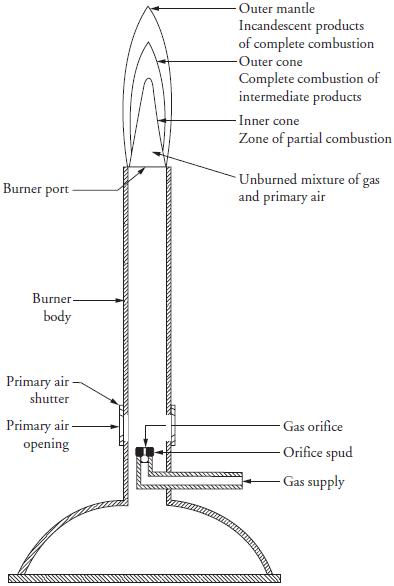
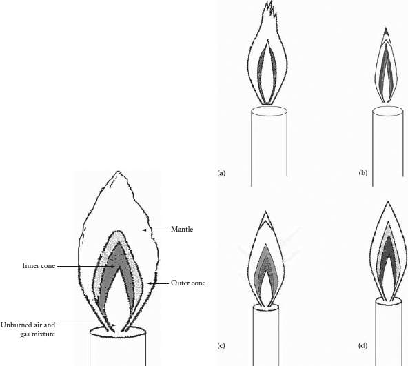
Appliance manufacturers had the freedom to tailor the flame patterns from the Bunsen burner design to design gas appliances. The Bunsen burner worked on the principle of introducing air into the mixture of the gas before it left the burner port. An orifice was used to regulate the gas flow within the burner body (Figure 8-6). Attached to the burner body is an adjustable shutter to control the primary air mixture that enters into it. The flame that is produced by the Bunsen burner has multiple colors within it. Each color within the flame marks a stage of the burning process of gas (Figure 8-7). The stages are as follows:
FIGURE 8-6 Bunsen burner.
FIGURE 8-7 Different fame types of a Bunsen burner, depending on the amount of oxygen supplied.
• The inner cone is the first stage of the burning process. Within this cone the gas is burned, which forms by-products, such as aldehydes, alcohols, carbon monoxide, and hydrogen.
• The outer cone surrounds the inner cone, and as air diffuses into the flame, it continues the burning process. If enough air is present during the burning process, the by-products from the inner cone will burn up in the outer cone. The by-products that are produced in the outer cone are carbon dioxide and water vapor.
• The outer mantle that is produced by the Bunsen burner is nearly invisible, with all the gas burned up. The reason it glows is due to the high temperature produced by the complete combustion of the gas products from the outer cone.
The temperature of a flame can vary, depending on what type of gas is used and how much air is pre-mixed with the gas. Temperatures within the flame will vary; the inner cone is cooler than the outer cone, and the hottest flame temperature is just above the outer cone.
Air Supply
When air is mixed with gas before it leaves the burner port, it is known as the primary air supply. Under ideal conditions, most burners only use 50 percent of the primary air supply to burn the gas, and the remaining 50 percent of the air is supplied by the secondary air supply from around the flames. In reality, additional excess air is needed to ensure that enough air is present to completely burn off the gas. The total air supply is accomplished by adding the sum of the primary, secondary, and excess air supplies. The total air supply needed for combustion is measured in percentages of air needed for complete combustion. Every manufacturer has its own specifications in the installation instructions or service manual for the total air percentages needed for the appliance model that you are servicing.
Flame Appearance
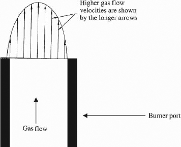
The appearance and stability of a flame is influenced by the amount of the primary air supply, the gas-burning speed, and the burner port. When the primary air supply is at 100 percent, under ideal conditions, the speed of burning is at its maximum. The speed of burning is also affected by the type of gas being burned. The flow velocity of the gas depends on the size of the orifice—the smaller the orifice size, the greater the flow velocity. Flow velocity from a burner port will also vary, depending on the size of the opening, with the greatest flow from the center of the port (Figure 8-8).
FIGURE 8-8 Flow velocities of gas.
After the air-gas mixture leaves the port, the flow velocity slows down, and the flame begins to stabilize when the flow velocity equals the burning speed. At the same time, the flame cone begins to take shape when the flow velocity of the air-gas mixture levels off when it leaves the burner port. The burning speed increases and the flame temperature increases near the top of the flame cone. Therefore, the shape of the flame cone is rounded off at its tip. The inner cone is determined by the effects of the velocity away from the centerline of the port for each layer of the flame burning.
Appliance manufacturers design gas appliances to have a stable burner flame by port loading. Port loading is expressed as BTU per hour per square inch of open burner port area. It is obtained by dividing the gas input rate by the total area of the port opening.
Flame Lifting
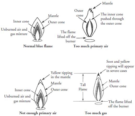
When enough primary air is introduced into a burner, a stabilized flame begins to form, and the flame burns quietly. If too much air is introduced, or if the port loadings are increased, the flame on the burner will have the tendency to lift (Figure 8-9). When the flames begin to lift (blowing) off the burner, they become very noisy. If this condition persists, the flame cones begin to rupture and complete combustion will not take place. In addition, the efficiency of the gas burner begins to drop along with the BTUs and the appliance begins to lose its heat content. If this condition is not corrected, aldehydes and carbon monoxide will begin filling the room.
FIGURE 8-9 Too much air supply will cause the fames to lift off the burner.
Additional flame-lifting possibilities include:
• Flame lifting is more likely to occur with natural gas appliances.
• Flame lifting will also occur if any operating or design factors cause the burner to decrease the burning speed.
• If any operating or design factors increase the flow velocity from the ports, flame lifting will occur.
• The port size and depth will affect flame lifting.
• Overrating the burners is a primary cause of flame lifting.
• A cold burner will cause the flame to lift, but it should settle down after a while.
Flashback
When the flame begins to ignite from within the burner head, a condition known as flashback occurs. This is caused when the reduced flow velocity of the air-gas mixture is less than the burning speed near the burner port. In other words, the inner flame cone becomes inverted and ignites the gas from within the burner port. If the burner is properly adjusted, flashback will not occur during normal operation of the gas appliance.
Additional flashback possibilities include:
• Flashback occurs in faster-burning gases.
• Flashback could occur when primary air is increased, which will increase the burning speed.
• Flashback occurs with underrated burners with incorrect orifice size.
• Incorrect gas pressure will cause flashback.
• Decreased flow velocities from a burner port will cause flashback.
• Leaking burner valves cause flashback.
• Flashback can occur when a burner is first turned on if the air-gas mixture is too rich or too lean.
When a burner is turned off, a condition known as “extinction pop,” or flashback on extinction, could occur. This could happen immediately, or it may take a few seconds. The extinction pop is caused by excessive air entering the burner when the gas burner valve is turned off. The reduced flow rate of the normal air-gas mixture in a burner is replaced with all air. In addition, it is possible for the flame speed to exceed the flow velocity of the gas, causing a flashback. This condition is not hazardous—it is just annoying to the appliance owner. With a burner that is properly designed, maintained, and adjusted, flashback will not occur under normal operating conditions.
Yellow Flame Tips
In gas appliances, if the primary air supply is reduced, the inner cones of the flames will begin to lengthen, and eventually they will disappear, turning the blue flame tips to yellow. If the primary air supply is cut off completely, the flames will turn yellow (Figure 8-10). When these yellow flames and glowing carbon particles impinge on a cool surface, they begin to quench the complete combustion process and the carbon particles will not burn off. In addition, carbon monoxide, soot, or both will begin to form when the yellow flames impinge on a cool surface.
FIGURE 8-10 Characteristics of gas fames.
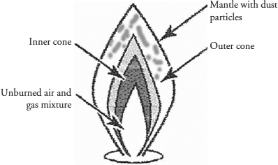
Dust particles in the air will begin to glow as they pass through a flame (Figure 8-11); the flame’s appearance begins to have color streaks. These streaks will appear orange-yellow and will not have an effect on complete combustion. The technician should not confuse dust particles with yellow flame tips. True yellow flame tips will be a pale yellow color and they can be eliminated by increasing the primary air supply. Depending on the air conditions of the surrounding area near the gas appliance, when you increase the primary air supply, you might also increase the amount of dust particles entering into the flame. Another way to distinguish yellow flame tips from dust particles is to put on a pair of brazing goggles and look into the flame. True yellow flame tips will not disappear.
FIGURE 8-11 Dust particles passing through a normal fame.
Appliance Burner Components
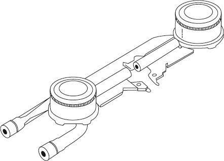
Over the years, appliance manufacturers have come out with many types of burner designs (see Figure 1-1 in Chapter 1 and Figure 8-12). In fact, appliance burners must have the following features:
FIGURE 8-12 A double gas burner.
• The burner design must be able to provide complete combustion of the gas.
• The burner design must provide for rapid ignition of the gas and be able to carry over the flame across the entire burner.
• The burner must operate reasonably quietly during ignition, burning, and extinction of the flame.
• The burner design must not allow for excessive flame lifting, flashback, or flame outage.
• The burner must provide uniform heat over the heated area.
• Most important to the consumer and manufacturer, the burner must have a long service life.
Gas Orifice
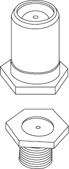
The gas orifice is not part of the burner, but it plays an important role in its operation (Figure 8-13). In the service field, the gas orifice goes by many names, such as orifice hood, spud, hood, or cap. The purpose of the gas orifice is to regulate or limit the flow of gas into the burner. The size of the hole in the orifice will depend on what type of gas is in use and what constant pressure is needed to light the burner evenly. Another reason for use of an orifice is to force primary air into the burner. Three types of orifices that are in use are:
FIGURE 8-13 Gas orifices are used to limit gas flow to burners.
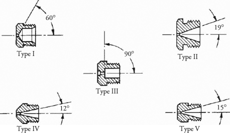
• The fixed orifice has a predetermined opening in the orifice hood to allow a certain rate of gas to flow (Figure 8-14).
FIGURE 8-14 Different types of fixed orifices.
• The adjustable orifice is mainly used in ranges. This type of orifice will allow you to control the gas rate, from zero to its maximum rated flow (Figure 8-15).
FIGURE 8-15 Adjustable orifices.
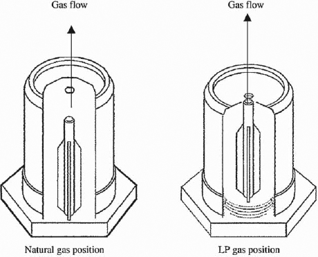
• The universal orifice is also mainly used on ranges. This type of orifice was designed to allow the range to be operated on natural or liquefied petroleum gas (Figure 8-16).
FIGURE 8-16 Universal orifices.
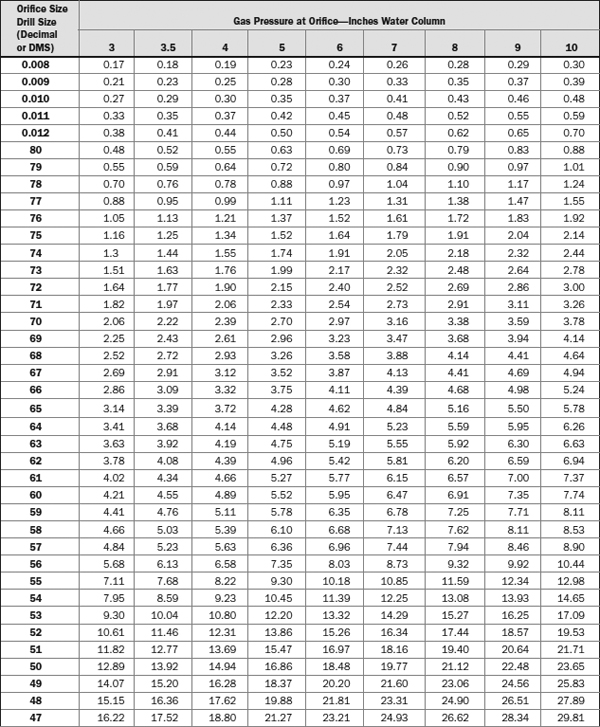
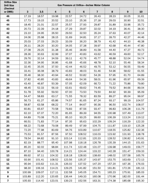
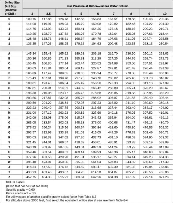
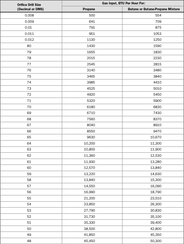
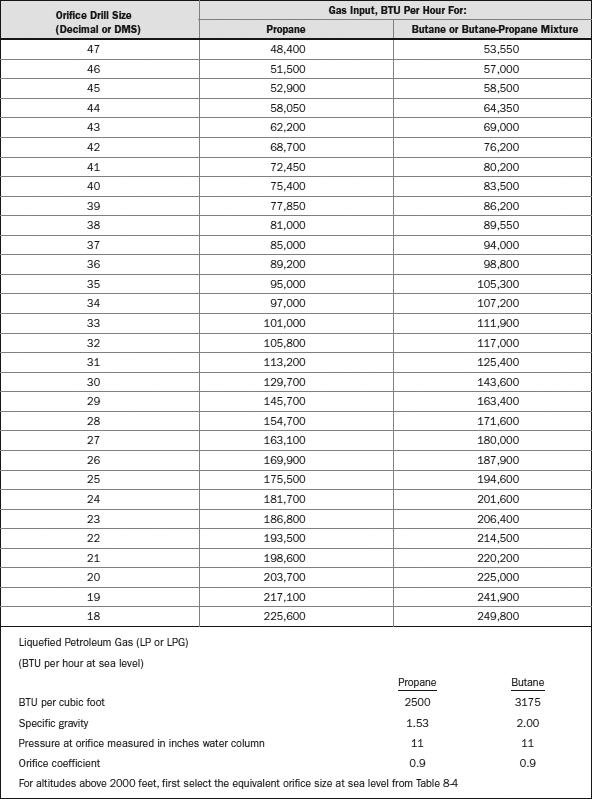
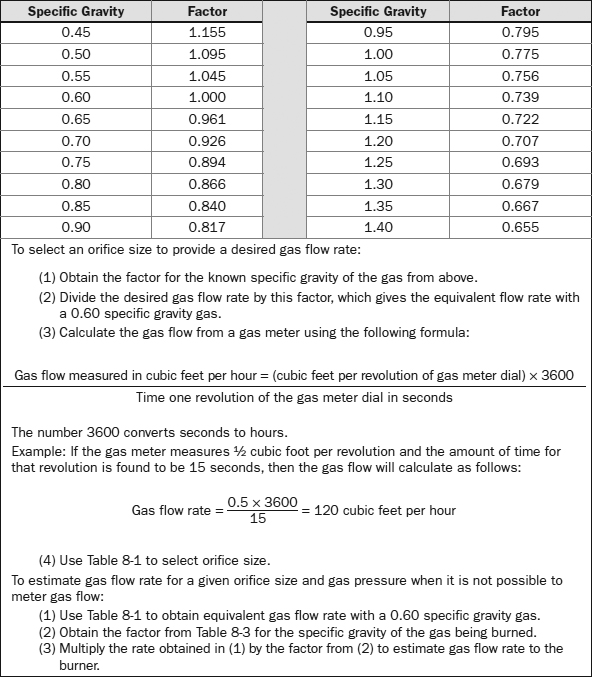
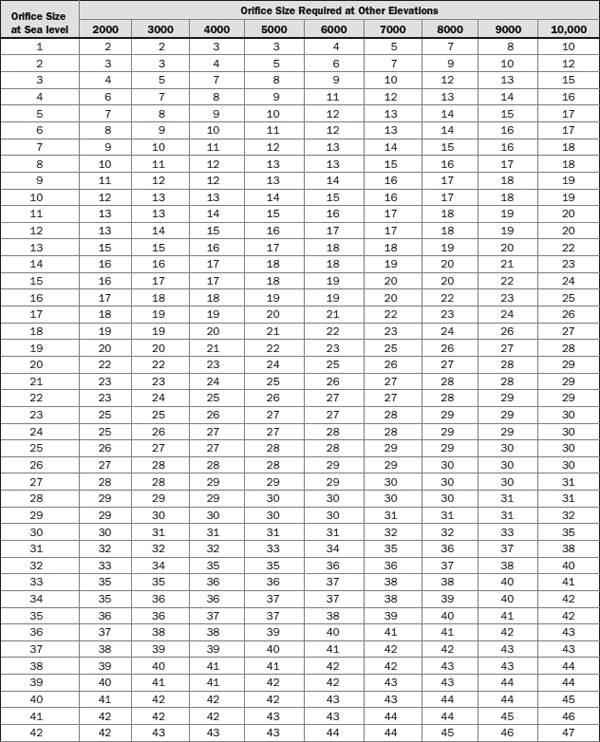
Most gas appliances that operate below the elevation of 2000 feet may not need to have the orifices replaced. If you have to replace the orifice, or if you have to check to see if the correct orifice size is installed, refer to Tables 8-1, 8-2, 8-3, and 8-4.
TABLE 8-1 Orifice Gas Pressure
TABLE 8-2 LP Orifice Drill Size
TABLE 8-3 Factors for Utility Gases of Another Specific Gravity
TABLE 8-4 Equivalent Orifice Sizes at High Altitudes
NOTE Gas appliances shipped from the manufacturer are set up for natural gas. If the home has LP gas, then the appliance will have to be converted for LP use.
Air Shutter
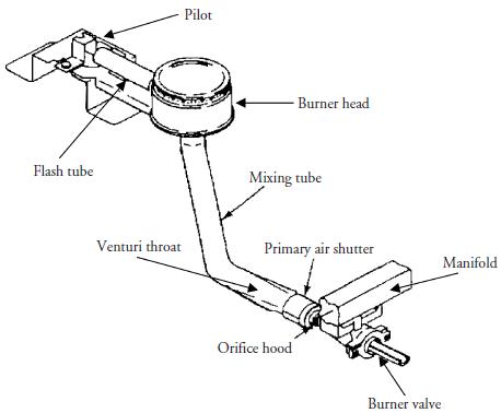
Most gas appliances have an adjustable primary air shutter to adjust the air intake, and they come in many designs. In addition, manufacturers have designed the air shutter to withstand rust and corrosion and to be secured in any position (Figure 8-17).
FIGURE 8-17 The primary air shutter is located at the end of the mixing tube. The burner head is designed with ports around the burner to allow for even burning and a blue fame.
Venturi Throat
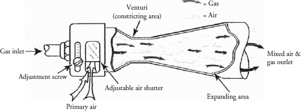
When gas passes through an orifice, it enters the throat of the mixing tube (Figure 8-18). Called the Venturi throat, this was designed to provide a more constant flow of primary air into the mixing tube of the burner.
FIGURE 8-18 The Venturi throat is incorporated into the mixing tube of the burner.
Mixing Tube
The mixing tube (see Figure 8-17) is designed to mix the air and gas uniformly after it leaves the Venturi throat but before entering the burner head.
Burner Head
When gas leaves the mixing tube, it enters the burner head, which contains the burner ports. The air-gas mixture is then distributed evenly among the burner ports. As the air-gas mixture emerges from the burner ports, it is lit with an ignition source. The size and shape of the burner head will allow even heat transfer to occur (see Figure 8-17).
Burner Ports
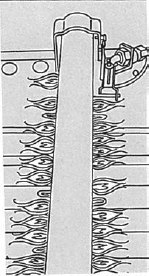
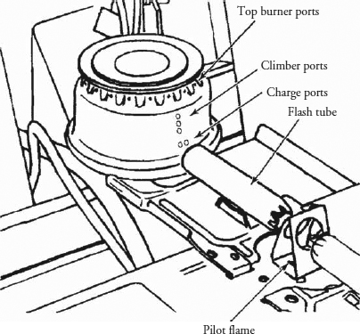
The burner ports (Figure 8-19) serve to distribute the flame evenly, provide even heat transfer, and provide a stable blue flame. In addition, when the flames are distributed throughout the burner ports, they will then pick up secondary air to assist in complete combustion.
FIGURE 8-19 The design of the burner ports and the location of the burner portholes.
Burner Operation
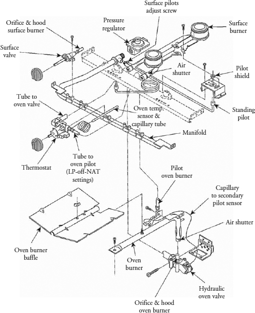
When the gas is turned on, whether by a knob or automatically by a control device, gas will flow from the supply line through a gas pressure regulator, gas manifold, burner valves, and orifice into the Venturi throat and mixing tube. The air-gas mixture then enters the burner head to be ignited. As the air-gas mixture leaves the burner head, when ignited, the flame begins to burn evenly around the burner head. Figure 8-20 illustrates an exploded view of the gas range’s components.
FIGURE 8-20 Exploded view illustrating the various components used in a gas range and their location.
Ventilation
When you properly install a ventilation system, it will serve the following important purposes:
• The by-products of hot combustion gases will be transported outside the home.
• The home will be protected from fire hazards.
• A ventilation system will provide good air circulation and adequate oxygen supply for the gas appliance and the occupants of the residence.
• It will remove the water vapors produced when burning gas.
A wide variety of venting options are available from vent manufacturers, and every gas appliance manufacturer will provide venting instructions for properly installing its products. It is strongly recommended that you follow these instructions. You must use the proper venting materials as described in the installation instructions for the model being installed, and install the venting system according to your local building codes. For additional information on proper ventilation, visit www.epa.gov/iaq/homes/hip-combustion.html.
Troubleshooting Ventilation Problems
The most common problems with ventilation systems are:
• Improper maintenance of the ventilation system
• Incorrect sizing and installation of the ventilation system
• Inadequate air supply
If you suspect a problem with the ventilation system, check the following:
• Make sure that you have the correct vent sizing.
• Check if there are too many elbows or if the length of the venting system exceeds the manufacturer’s recommendations or local building codes.
• Inspect the entire ventilation system for faults, such as a disconnected or crushed pipe.
• Inspect for an obstruction, such as a clogged vent cap.
• Inspect all air openings for obstructions.
Measuring Gas Pressure
When installing or repairing gas appliances, it is often necessary to measure the pressure of the gas supply to the appliance. There also may be times when the technician will have to test the gas pressures at the manifold or orifices. The two types of test instruments used today to test the gas pressures are the manometer and the magnehelic gauge.
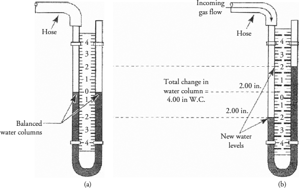
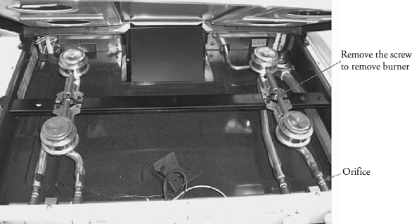
The manometer is a U-shaped tube equipped with a scale to measure gas pressure in water column inches (Figure 8-21). Before you check the gas pressure on an appliance, locate the model and serial number nameplate. This nameplate will have the gas rating stamped on it. Now turn off the gas supply to the appliance. Before you can begin to test the gas pressure, you must first set up the manometer by adding water to the U-shaped tube until both columns read zero on the scale (Figure 8-22a). If reading the scale is difficult, you can add a food coloring to the water to enhance the color so that you can read the scale better. When measuring gas pressure in an appliance, the tubing from the manometer is attached to the orifice, manifold, or gas supply line, and the other end of the tube on the manometer is left open to the room atmosphere. To test the gas pressure at the burner orifice, remove the burner (Figure 8-23). Next, attach the long hose from the manometer to the burner orifice. Now turn on the gas supply to the appliance. In addition, turn on the burner valve being tested, and turn on one other burner to serve as the load. When the gas pressure is applied to the manometer, it pushes down on the water column and the water column rises on the other side of the manometer (Figure 8-22b). To read the manometer scale, observe where the water column stops. In Figure 8-22b, the incoming gas has pushed the water in the manometer down 2 inches below zero, and the water column on the other side is pushed up 2 inches above zero. The pressure reading is obtained by adding the two readings together. Figure 8-22b shows that the total change equals a 4-inch water column. The reading should be within the rating on the model and serial nameplate.
FIGURE 8-21 A manometer. This instrument is used to test gas pressure.
FIGURE 8-22 (a) Before using a manometer, check to see if the columns have equal amounts of water. (b) When reading a manometer, you add the change in both columns; the sum equals the pressure of the gas.
FIGURE 8-23 Removing the burner to test the gas pressure at the gas valve.
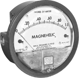
The magnehelic gauge shown in Figure 8-24 also measures gas pressure. This gauge can measure gas pressure faster than the manometer can. To use this type of gauge, just follow the same procedures for the manometer. The only difference is that you read the gas pressure directly from the gauge scale. Some models have different scales on the gauge dial—just read the gauge that indicates water column pressure.
FIGURE 8-24 A magnehelic gauge. This instrument is used to test gas pressure.
Many companies manufacture test instruments for checking gas pressures. Websites to check out include:
Testing for Gas Leaks
When testing for a gas leak, do not use a lighter or a lit match. That is not the safe or correct way to test for gas leaks. All gas appliances, when they are installed or repaired, must be tested for leaks before placing the appliance in operation. Remember, LP or LPG gas is heavier than air and settles in low-lying areas. If you do not have a combustible gas detector (and I recommend that you purchase one), use your nose to smell for a gas leak all around the appliance at floor level. A safe and effective way to test for gas leaks is to use a chloride-free soap-and-water solution to check all connections and fittings. The solution can be sprayed, applied directly, or an applicator can be used to spread the solution. If a gas leak is detected by the soap solution it will begin to form bubbles.
Sometimes, air might be present in the gas lines from installation or repairs, and it could prevent the pilot or burner from lighting on initial startup. The gas lines should be purged of air in a well-vented area. Before proceeding with purging the gas lines, inspect the work area for any other sources of ignition, such as flames, burning candles, running electrical appliances, etc. With a safe working environment, you can begin to purge the gas lines. On gas ranges/ovens, just turn on the burners until you smell the gas or until the burners are lit properly. With gas dryers and gas water heaters, turn off the gas supply valve. Remove the gas line from the appliance, and slowly begin to turn on the gas supply valve. When you begin to smell gas, turn off the main supply valve. Next, reconnect the gas line to the appliance, open the gas supply valve, and test for gas leaks. If there are no gas leaks, run the appliance.
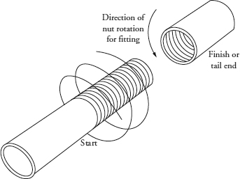
Use an approved pipe joint compound for connecting gas piping and fittings to the appliance. In addition, never use white Teflon tape on gas lines. White Teflon tape does not guarantee a leak-free connection. You can use a PTFE yellow Teflon tape on gas connections and fittings. This type of approved Teflon tape is a specially designed thread-sealing tape for use on gas appliances. To attach PTFE yellow Teflon tape to pipe thread, wrap the tape in the direction with the thread, as shown in Figure 8-25.
FIGURE 8-25 Wrap tape in the thread direction on a pipe fitting.
Combustible Gas Detector
Combustible gas detectors are another general-purpose tool that the service technician could use to detect gas leaks (Figure 8-26). This instrument uses an audible alarm that gets louder when you approach a gas leak. This device has the capabilities of detecting LP (LPG) or natural gas and other hydrocarbons and halogenated hydrocarbons, depending on the manufacturer. The sensitivity of a combustible gas detector can be between 50 and 1500 ppm of gas detection, with an instantaneous response.
FIGURE 8-26 A combustible gas detector. This meter is used for detecting gas leaks.
One manufacturer of combustible gas detectors can be viewed on the Web at www.aprobe.com.
Gas Conversion Procedures
Before installing a new gas appliance, look at the model and serial dataplate to determine that the appliance is made for the type of gas supplied in the home. Do not install an LP or LPG gas appliance when natural gas is supplied to the home. Conversely, do not install a natural gas appliance when LP or LPG gas is supplied to the home.
Appliance manufacturers do make gas appliances that can be installed with either LP or natural gas. All you have to do is follow the manufacturer’s recommendations for converting the appliance from one type of gas to the other.
Gas Pressure Regulator
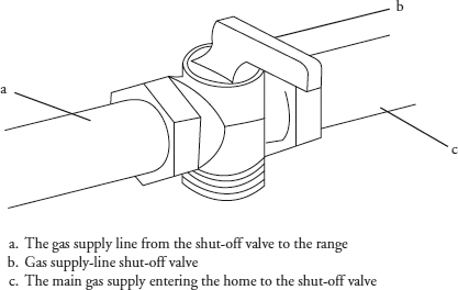
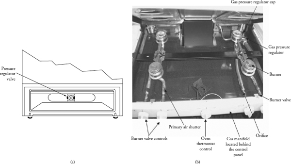
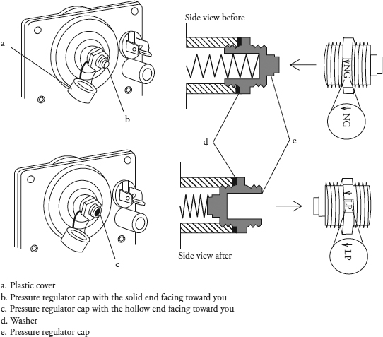
To convert a gas pressure regulator from one type of gas to the other, you must first shut off the main gas supply to the appliance (Figure 8-27). Also, if the gas range has an electrical connection, turn off the electricity. Locate the gas pressure regulator valve. On some models, the gas pressure regulator valve is located in the lower rear of the range (Figure 8-28a) or under the cooktop (Figure 8-28b). To convert the gas pressure regulator valve, you do not have to remove it from the range. Just gain access to it. As you can see in Figure 8-29, remove the plastic cover from the regulator cap. Next, unscrew the gas pressure regulator cap with a wrench; turn it counterclockwise to remove the cap and leave the spring in the regulator.
FIGURE 8-27 The main gas supply shut-off valve.
FIGURE 8-28 (a) On some models, the gas pressure regulator is located in the rear of the range behind the lower drawer. (b) The location of gas components under the range cooktop.
FIGURE 8-29 (a) Plastic cover. (b) Pressure regulator cap with the solid end facing outward for natural gas. (c) Pressure regulator cap with the hollow end facing outwards for LPG gas. (d) Washer. (e) Gas pressure regulator cap.
NOTE In Figure 8-29, the regulator cap has a gas designation stamped on it.
For LP gas operation, the “<-LP” indicator must face in the direction of the gas pressure regulator, and the hollow end faces away from the regulator. For natural gas operation, the “<-NG” indicator must face in the direction of the regulator, with the dimple end facing away from the valve. Reinstall the cap and tighten with a wrench in the clockwise direction. Do not overtighten the cap, as you might damage it. Finally, replace the plastic cover on the regulator cap.
Converting Surface Burners
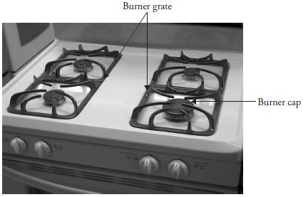
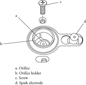
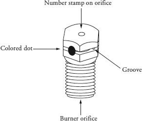
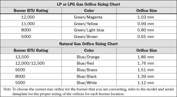
To convert the surface burners from one type of gas to the other, you must first shut off the main gas supply to the appliance (see Figure 8-27). Also, if the gas range has an electrical connection, turn off the electricity. Remove the burner grate and burner cap (Figure 8-30). Remove the screws from the burner base, and reinstall one screw to hold the orifice holder (Figure 8-31) secured to the cooktop. This will steady the orifice holder so that you can remove the orifice without damaging the orifice holder. To remove the orifice, use a 5/16 nut driver with masking tape applied to the end of it. The masking tape will hold the orifice in the nut driver when you remove it. Turn the nut driver counterclockwise to remove the orifice. Locate the extra orifices that came with the range. Most likely, they will be attached somewhere near the main gas inlet in a holder or small bag. To choose the correct size orifice for the burner that you are converting, refer to the model and serial dataplate. Orifices are stamped with a number and are color-coded, with a groove in the center side of the hex head (Figure 8-32). Use Table 8-5 for the proper sizing of the orifices. With the correct orifice size in hand, just reverse the order of disassembly, and reassemble the burner.
FIGURE 8-30 The gas range, burner, and grate location.
FIGURE 8-31 Location of orifice on a drip-proof burner after the burner cap is removed.
FIGURE 8-32 The burner orifice.
If the range you are servicing resembles the one in Figure 8-28, convert the burner by first removing the screw that secures it to the burner bar. Remove the burner by lifting it up and out of the range. The orifice is now ready to be converted. To convert the orifice from natural to LP gas, use a wrench around the orifice head and turn the orifice clockwise to seat the orifice. Do not overtighten; you might damage the orifice opening. On some models, the orifice hood will be replaced entirely with the correct orifice size for the type of gas used. With the correct orifice adjustment completed, just reverse the order of disassembly, and reassemble the burner.
TABLE 8-5 LP or LPG Gas Orifice Sizing Chart
Converting the Oven Bake Burner
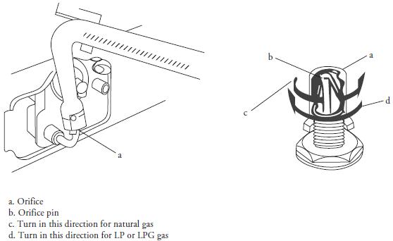
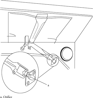
To convert the oven bake burner from one type of gas to the other, you must first shut off the main gas supply to the appliance (see Figure 8-27). Also, if the gas range has an electrical connection, turn off the electricity. When converting the oven bake burner, remove the racks and gain access to the oven burner (Figure 8-33). Place a wrench on the orifice, and turn the wrench clockwise for the LP gas setting. Turn the wrench in a counterclockwise direction for natural gas. Only turn the wrench about two or two and a half turns. Do not overtighten the orifice hood; you might damage the orifice pin. With the correct orifice adjustment completed, just reverse the order of disassembly, and reassemble the oven.
FIGURE 8-33 The oven burner is located underneath the bottom oven cover. Remove the racks and lift out the bottom cover for access.
Converting the Oven Broil Burner
To convert the oven broil burner from one type of gas to the other, you must first shut off the main gas supply to the appliance (see Figure 8-27). Also, if the gas range has an electrical connection, turn off the electricity. When converting the oven broil burner, gain access to the burner (Figure 8-34). Use a wrench to turn the orifice hood counterclockwise for natural gas or clockwise for LP or LPG gas. Only turn the wrench about two or two and a half turns. Do not overtighten the orifice hood; you might damage the orifice pin. With the correct orifice adjustment completed, just reverse the order of disassembly, and reassemble the oven.
FIGURE 8-34 The broiler burner location.
Converting the Bake/Broil Thermostat
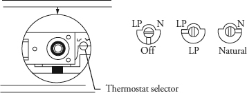
Gas ranges with oven pilot lights will have to be converted from one type of gas to the other. Remove the oven thermostat knob to expose the oven thermostat selector. Insert a small screwdriver into the pilot control screw, turn the screw clockwise for LP or LPG gas or counterclockwise for natural gas (Figure 8-35). Replace the oven thermostat knob. Gas ranges with electronic spark ignition for pilot control will be discussed later in the book.
FIGURE 8-35 Oven pilot conversion. The pilot control screw is located behind the thermostat knob.
Gas Appliance Maintenance
To maintain gas appliances, always follow the manufacturer’s recommendations for periodic maintenance as stated in the use and care manual. The range, oven, or cooktop can be cleaned with warm water, mild detergent, and a soft cloth on all cleanable parts, as recommended in the use and care manual. Also, never use abrasive cleaners that are not recommended by the manufacturer.
Do not allow grease spillovers to accumulate after cooking on top of the range; it will become a fire hazard. When cleaning the burners, always make sure that all of the portholes are free of debris. If, for any reason, the burner portholes are blocked, the flame appearance will be different. Blocked portholes will reduce gas flow, and the heating value of the burner will be reduced. Maintenance procedures for gas water heaters and gas dryers will be discussed in later chapters.
