9
CHAPTER
Principles of Air Conditioning and Refrigeration
M any excellent books have been written on the subject of air conditioning and refrigeration, and this chapter will only cover the basics needed to diagnose and repair the electrical portion of domestic refrigerators and room air conditioners (RACs). The chapter will cover the refrigeration process, but will not cover the replacement procedures of any sealed system components. This is a specialized area, and only an EPA-certified technician can repair the sealed system of a refrigerator or air conditioner (AC). The HVAC/R-certified technician has the proper training, tools, and equipment required to make the necessary repairs to the sealed system. An individual who is not certified to service the sealed system could raise the risk of personal injury, as well as property damage. The uncertified individual could void the manufacturer’s warranty on the product if he or she attempts entry into the sealed system.
Introduction to Air Conditioning and Refrigeration
Before the 1900s and mechanical refrigeration, people cooled their foods with ice and snow. The ice and snow were transported long distances and stored in cellars below ground or in icehouses. Refrigeration is the process of removing heat from an enclosed area, thus lowering the temperature in it. Air conditioning and refrigeration began to come to life in the early 1900s. The first practical refrigerating machine was invented in 1834, and it was improved a decade later.
The two most important figures involved with refrigeration and air conditioning were John Gorrie and Willis Carrier. John Gorrie, an early pioneer of refrigeration and air conditioning, was granted a patent in 1851 for his invention of the first commercial refrigeration machine to produce ice. Improvements were made to Gorrie’s invention in the late 1880s, and the reciprocating compressor was used commercially in meat and fish plants and for ice production. In 1902, Willis Carrier designed and invented the first modern air conditioning system, and in 1922, Carrier invented the first centrifugal refrigeration machine. Willis Carrier went on to found the company we know today as Carrier Corporation. Toward the end of the 1920s, the first self-contained room air conditioner was introduced.
Refrigerators from the late 1880s until 1929 used ammonia, methyl chloride, or sulfur dioxide as refrigerants. These refrigerants were highly toxic and deadly if a leak occurred. In 1931, the DuPont Company began producing commercial amounts of “R-12,” also known by its trade name “Freon.” With safer refrigerants being introduced, the refrigerator and air conditioner market began to grow. Only half a century later did people realize that these chlorofluorocarbons endangered the earth’s ozone layer. Today, refrigerant companies are working harder to produce even safer refrigerants that will not endanger the earth’s ozone layer.
Saving the Ozone Layer
High above the earth is a layer of ozone gas that encircles the planet. The purpose of the gas is to block out most of the damaging ultraviolet rays from the sun. Such compounds as CFCs, HCFCs, and halons have depleted the ozone layer, allowing more ultraviolet (UV) radiation to penetrate to the earth’s surface.
In 1987, the United States, the European Economic Community, and 23 other nations signed the Montreal Protocol on Substances that Deplete the Ozone Layer. The purpose of this agreement was to reduce the use of CFCs throughout the world. To strengthen the original provisions of this protocol, 55 nations signed an agreement in London on June 29, 1990. At this second meeting, they passed amendments that called for a full phaseout of CFCs and halons by the year 2000. Also passed at that meeting was the phaseout of HCFCs by the year 2020, if feasible, and no later than the year 2040, in any case.
On November 15, 1990, President George H.W. Bush signed the 1990 Amendment to the Clean Air Act, which established the National Recycling and Emissions Reduction Program. This program minimizes the use of CFCs and other substances harmful to the environment, while calling for the capture and recycling of these substances. The provisions of the Clean Air Act are more stringent than those contained in the Montreal Protocol as revised in 1990.
Beginning on July 1, 1992, the Environmental Protection Agency (EPA) developed regulations under Section 608 of the Clean Air Act (the Act) that limit emissions of ozone-depleting compounds. Some of these compounds are known as chlorofluorocarbons (CFCs) and hydrochlorofluorocarbons (HCFCs). The Act also prohibits releasing refrigerant into the atmosphere while maintaining, servicing, repairing, or disposing of refrigeration and air conditioning equipment. These regulations also require technician certification programs. A sales restriction on refrigerant is also included, whereby only certified technicians will legally be authorized to purchase such refrigerant. In addition, the penalties and fines for violating these regulations can be rather severe.
In 1993, Section 605 of the Clean Air Act established the phaseout framework. This is an accelerated phaseout of class II controlled substances (including R-22). It also limited production and consumption of R-22 between 2010 and 2020 to the servicing of equipment manufactured prior to January 1, 2010.
By January 1, 2015, The Montreal Protocol requires the United States to reduce its consumption of HCFCs by 90 percent below the U.S. baseline, and by January 1, 2020, the United States needs to reduce its consumption of HCFCs by 99.5 percent below the U.S. baseline.
Matter
In order to understand how refrigeration and air conditioners work, it is necessary to understand several basic laws of matter. There are currently five states of matter: solid, liquid, gas, plasma, and Bose-Einstein condensate.
In our discussion of matter, only three of the five states apply to air conditioning and refrigeration (Figure 9-1):
• Matter in the form of a solid will retain its shape and volume without a container. The molecules within a solid are compressed and bound together, and under normal conditions will not move at all.
• Matter in the form of a liquid will take the shape of its container, without losing any volume if not under pressure. Light-density fluids, such as water, will eventually lose some of their volume due to evaporation. The molecules within a liquid are spaced apart from each other and are constantly on the move.
• Matter in the form of a gas will take the shape and volume of its container and will expand to fill the container. The molecules within a gas are spaced far apart from each other.
FIGURE 9-1 The three states of matter that pertain to air conditioning and refrigeration.
Change of State
There are five principles regarding how matter can change from one form to another. When matter is heated, cooled, or an increase or decrease of pressure occurs, matter will be transformed to another state:
• Liquefaction occurs when matter changes from a solid to a liquid. For example, an ice cube will begin to change state when heat is applied.
• Solidification occurs when matter changes from a liquid to a solid. For example, when the temperature of water reaches its freezing point, it will freeze and become a solid.
• Vaporization occurs when a liquid matter like water is heated to its boiling point and transforms into a vapor.
• Condensation occurs when a vapor transforms into a liquid. For example, when water vapor is boiled off into steam in a closed vessel and then allowed to cool down, it will begin to turn back into a liquid.
• Sublimation can occur when a solid matter transforms into a vapor without passing through the liquid state. For example, carbon dioxide in a solid form (dry ice) at atmospheric pressure will transform into a vapor state at normal temperatures, thus bypassing the liquid state.
Law of Thermodynamics
Energy exists in many forms, such as heat, light, mechanical, chemical, and electrical energy. The first law of thermodynamics is the study of that energy. Energy itself is the ability to do work, and heat is only one form of energy—ultimately, all forms of energy end up as heat energy. The first law of thermodynamics states that energy cannot be created or destroyed; it can only be converted from one form to another.
The second law of thermodynamics as it pertains to air conditioning and refrigeration deals with heat energy travel. The law states that heat energy can only travel in one direction—from hot to cold. When two objects are placed together, heat will travel from the warmer object to the cooler object until the temperatures of both objects are equal; only then will heat transfer stop. The rate of travel will depend on the temperature difference between the objects. The greater the temperature difference between the objects, the faster heat will travel to the cooler object.
It’s All About Heat
Heat is a form of energy that:
• Causes temperatures to rise in an object
• Has the capacity to do work
• Has the ability to flow from a warmer substance to a cooler one
• Can be converted to other forms of energy
Heat energy can be measured with a thermometer. The scales used are Fahrenheit (F) and Celsius (C). Heat intensity has three reference points: freezing point (32 degrees F or 0 degrees C), boiling point (212 degrees F and 100 degrees C), and absolute zero (–470 degrees F or -273 degrees C). This third reference point is believed to be where all molecular action ceases.
Another way to measure heat energy is in units called British Thermal Units (BTUs). A BTU represents the amount of heat required to raise the temperature of 1 pound of water 1 degree Fahrenheit at sea level. All refrigeration equipment and air conditioning equipment are rated in terms of how many BTUs of cooling or heating they can remove or put into a given area.
On larger room air conditioners and central air conditioning, it is necessary to calculate the heat load and heat gain of a given area to properly size the unit. The same is required for large refrigeration equipment and commercial refrigeration.
Methods of Heat Transfer
Heat energy is an important concern in refrigeration and air conditioning. The room air conditioner and domestic refrigerator must be able to remove the heat from a given area and transport it to an area outside of the cabinet or room. Heat transfer will take place using one or more of the following basic transfer methods:
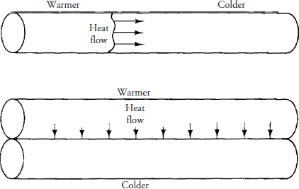
• Conduction occurs when two objects are in contact with each other and heat transfers from one object to another (Figure 9-2). The rate of heat transfer will depend on the makeup of the materials used. Conduction will also occur in a single object. For example, if one end of a solid metal rod is heated, the heat will travel toward the cooler end of the rod. Copper and aluminum are good conductors of heat and are used mostly in air conditioners and refrigerators.
FIGURE 9-2 The transfer of heat from a warmer object to a cooler object is known as conduction.
• Convection occurs when heat transfers are caused by air movement or fluid movement, whether naturally or by the means of forced air movement (Figures 9-3 and 9-7). Using the refrigerator as an example, the forced air moving over the cold evaporator coil will cause the air to become colder and denser, and it begins to fall to the bottom of the cabinet. In doing so, the air will absorb the heat from the food and air within the refrigerator cabinet. With the heat absorbed in the colder air, it will begin to expand and become lighter; it will rise and, once again, it will be exposed to the colder evaporator coil temperatures, where heat will transfer to the cold coils. This cycle will continue until the temperature requirements are met. Convection also occurs in a liquid when heat transfers in and out of the liquid, as in a refrigerant used in the sealed system of
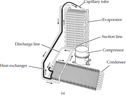
FIGURE 9-3 The refrigeration cycle.
• Radiation is the travel of heat energy through the atmosphere by means of radiant waves (light or radio frequency). It travels in a straight path, does not heat the air, and heats only a solid object. For example, if you are standing outside directly in the sunlight, it feels much hotter than if you were to stand in the shade outside. This type of heat transfer comes into play when the refrigerator door is opened or a window covering is opened in an air-conditioned room, allowing heat to enter by radiation. The amount of heat transferred into a refrigerator cabinet or air-conditioned room depends on the temperature difference between the atmosphere and the object.
Refrigerants
Refrigeration involves the process of lowering the temperature of a substance or cooling a designated area. Manufacturers must consider safety, reliability, environmental acceptability, performance, and economics of each refrigerant that is used in refrigeration and air conditioning. The product that absorbs the heat from a substance to be cooled is known as a refrigerant. Refrigerants are classified into two main groups. The first group will absorb the heat by having the refrigerant go through a change of state; the second group involves the absorption of heat without changing the state of the refrigerant. A secondary refrigerant is a refrigerant that will transport the “cold” or “hot” from one location to another (water, for example). The most widely used method of refrigeration is known as the vapor compression cycle (refrigeration cycle using a compressor), which relies on the evaporation of a liquid. This type of method is widely used in domestic refrigeration and air conditioning.
Refrigerants are made up of chemical compounds that are used in a sealed refrigeration system of an air conditioner or refrigerator. They absorb the heat by the process of evaporation or boiling the refrigerant, thereby changing it from a liquid state to a gaseous state. Refrigerants have a much lower boiling point than water when it begins to change state. To remove the heat from the refrigerants, they must be able to change back into a liquid state by the process known as condensation.
Refrigerants are classified into three groups according to their flammability:
• Class 1 Nonflammable refrigerant
• Class 2 Moderately flammable refrigerant
• Class 3 Highly flammable refrigerant
A refrigeration system’s reliability will also depend on the chemical stability of the refrigerant, its compatibility with the components within the refrigeration circuit, and the type of lubricant used. At all times, the refrigerant should be miscible at various temperatures with the oil used in the compressor to ensure that the oil will circulate throughout the refrigeration circuit and return to the compressor, where it belongs.
The refrigerant used in a domestic refrigerator or freezer is R-134a. The refrigerant used in room air conditioners is R-22, which will be phased out and replaced with R410a. Other substitute refrigerants are being used today as well.
Special note: Before charging a sealed system the technician must verify the type of refrigerant being used in the product.
Remember: You must be certified to repair sealed refrigeration systems.
When a sealed system has to be repaired, the acceptable method for recharging the product is the weighed-in method. The weight of the refrigerant, usually in ounces, is weighed; this is the most accurate method of refilling the sealed system. Also, these small refrigeration systems are hermetically sealed from the factory, and the manufacturer requires that the products be hermetically resealed again after the repairs are made.
Tables 9-1, 9-2, and 9-3 illustrate the different types of refrigerants used in modern refrigeration and air conditioning equipment.
TABLE 9-2 Other Types of Refrigerants
TABLE 9-3 Refrigerant Components, Types, and Lubricants
Room Air Conditioner vs. Refrigerator/Freezer
A room air conditioner (RAC) consists of a cabinet, a sealed refrigeration system (see Figure 1-16 and Figure 9-3), and the electrical circuitry, including the fan motor and other components. The RAC will circulate air (Figure 9-4), remove the humidity in a room, filter out the dust particles, and maintain a desired temperature within the room. Some RAC models are equipped with electric heating elements or reverse-cycle heating. Room air conditioners are less expensive than central air conditioning, and they are easier to install. The RAC refrigeration cycle is similar to the refrigeration cycle of a refrigerator/freezer. The only physical difference is in the packaging of the appliance (Figure 9-5).
FIGURE 9-4 The airflow patterns of a room air conditioner.
FIGURE 9-5 Typical component locations in a room air conditioner (RAC).
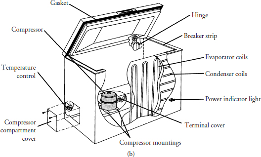
A refrigerator/freezer consists of a cabinet, a sealed refrigeration system (Figure 9-6a, b, c, and d), and the electrical circuitry. It circulates the air (Figure 9-7), removes humidity, and controls the temperature within a closed cabinet that prevents food from spoiling. The refrigerator/freezer refrigeration cycle is similar to the refrigeration cycle of a room air conditioner.
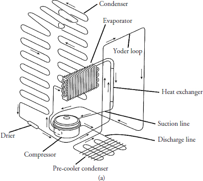
FIGURE 9-6 Typical components of a sealed refrigeration system.
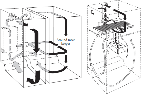
FIGURE 9-7 The cold airflow pattern in side-by-side and two-door refrigerators.
The temperature range for a refrigerator or freezer will range from –20 degrees Fahrenheit to 45 degrees Fahrenheit. A room air conditioner’s temperature range varies from 60 degrees to 86 degrees Fahrenheit.
The Basic Refrigeration Cycle
A service technician needs a good understanding of the refrigeration cycle in order to diagnose a refrigerator, freezer, or air conditioner. Without this understanding, the technician will not be able to diagnose a sealed system problem correctly. Mechanical refrigeration is accomplished by continuously circulating, evaporating, and condensing a fixed supply of refrigerant in a closed system. Evaporation occurs at a low temperature and low pressure, while condensation occurs at a high temperature and high pressure. Thus, it is possible to transfer heat from an area of low temperature (that is, the refrigerator cabinet) to an area of high temperature (that is, the kitchen area).
There are five components that make up the refrigeration cycle (Figures 9-3 and 9-6a, b, c, and d). They are
1. Compressor
2. Condenser coil
3. Metering device
4. Evaporator coil
5. Refrigerant
Let’s start the refrigeration cycle at the compressor. The compressor, also known as a vapor pump, is the heart of the refrigeration cycle. Once the compressor has started, the suction side of the compressor will draw in a superheated, low-pressure, low-temperature vapor refrigerant from the evaporator. This vapor is then compressed by the compressor piston into a high-pressure, high-temperature, and superheated vapor. When the refrigerant exits from the compressor discharge side and enters into the discharge line, it is a high-pressure, superheated vapor. The refrigerant will then travel to and enter the condenser coil, giving up some of its heat upon entry.
The beginning portion of the condenser coil is often referred to as the desuperheating section and the refrigerant is in the 100 percent vapor state. Around the middle of the condenser coil, the refrigerant gives up latent heat and begins to condense. At this point, the refrigerant’s state is 50 percent liquid and 50 percent vapor. As the refrigerant continues to travel and condense in the condenser coil, the liquid refrigerant increases and the vapor refrigerant decreases. During this time the refrigerant temperature remains stable. At the bottom of the condenser coil, the refrigerant will become 100 percent subcooled liquid, and the temperature of the refrigerant is also reduced. The subcooled refrigerant will prevent the refrigerant from boiling. The boiling of the refrigerant at the bottom of the condenser coil is known as flash gas. If this flash gas happens, the capacity of the sealed system would be reduced. To prevent this from happening, we must subcool the refrigerant before it reaches the metering device.
The condenser coil’s main purpose is to allow the refrigerant to give up its heat. As the refrigerant circulates through the condenser coil, the condenser fan motor will circulate the surrounding air through the condenser coil. As the air passes over the condenser coil, heat will transfer from the refrigerant to the surrounding air.
Inside the condenser coil, the temperature of the high-pressure vapor refrigerant will determine the temperature at which condensation begins. Condensation usually begins when the refrigerant is approximately 30 degrees Fahrenheit higher than the surrounding air temperature. At that point, heat will transfer from the refrigerant to the surrounding air. The state of the refrigerant when it enters the liquid line is 100 percent liquid.
The liquid refrigerant now enters the metering device. The flow of refrigerant into the evaporator is controlled by the pressure differential across the metering device. The metering device for refrigerators, freezers, residential ice machines, and room air conditioners is called the capillary tube. The capillary tube has a very small diameter opening at both ends and is constructed out of copper tubing, with a predetermined length. This type of metering device will control and measure the flow of refrigerant into the evaporator coil. The location of the metering device is at the end of the liquid line before the inlet of the evaporator coil.
When the refrigerant leaves the metering device, the refrigerant is 75 percent liquid and 25 percent vapor. As the high-pressure liquid refrigerant enters the evaporator coil, it is subjected to a much lower pressure due to the suction of the compressor and the pressure drop across the metering device. Thus the refrigerant tends to expand and evaporate. In order to evaporate, the liquid must absorb heat from the air passing over the evaporator coil. The liquid refrigerant in the evaporator coil will begin to boil and vaporize. This is called latent heat of vaporization. About midway in the evaporator coil the state of the refrigerant is 50 percent liquid and 50 percent vapor.
As the refrigerant moves through the evaporator coil, it goes from a saturated liquid to a more saturated vapor. When the refrigerant leaves the evaporator coil, it is superheated vapor. This superheated vapor returns to the compressor to begin the cycle over again.
Eventually, the desired air temperature is reached and the thermostat, or cold control, will break the electrical circuit to the compressor motor and stop the compressor. As the temperature of the air running through the evaporator rises, the thermostat reestablishes the electrical circuit. The compressor starts, and the refrigeration cycle continues.
It is extremely important to analyze every system completely and understand the intended function of each component before attempting to determine the cause of a malfunction or failure.
Refrigeration Components
As a new technician, you may understand the process of a refrigeration cycle, but you must also understand how each component functions in the refrigeration cycle. Each component has a specific job to assist in maintaining the objective of removing heat from a given area.
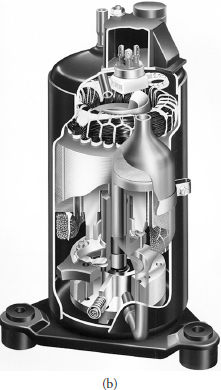
Compressor
The compressor (see Figures 9-8a, b, and c) is the heart of the vapor compression system, also known as the pump. All refrigerant circulating within the sealed system must pass through the compressor. This component has two functions within the refrigeration cycle:
• Retrieve the refrigerant vapor from the evaporator, thereby maintaining a constant pressure and temperature
• Increase the refrigerant vapor pressure and temperature to allow the refrigerant to give up its heat in the condenser coil
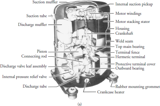
FIGURE 9-8a The internal view and identification of the internal components in a hermetically sealed air conditioner compressor.
FIGURE 9-8b An internal view of a rotary compressor.
FIGURE 9-8c An internal view of a compressor.
Compressors used for domestic refrigeration and room air conditioners are either reciprocating or rotary in design and are hermetically sealed. A hermetically sealed compressor cannot be repaired in the field; it can only be replaced as a complete unit by a certified technician. The electric motor within the compressor can be tested using a multimeter to determine if the windings of the motor are good or bad.
Compressor Safety
In the interest of promoting safety in the refrigeration and air conditioning industry, Tecumseh Products Company has prepared the following information to assist service personnel in safely installing and servicing equipment. This section covers a number of topics related to safety. However, it is not designed to be comprehensive or to replace the training required for professional service personnel.
Trained Personnel Only
Refrigeration and air conditioning devices are extremely complicated by nature. Servicing, repairing, and troubleshooting these products should be done only by those with the necessary knowledge, training, equipment, and certification.
Terminal Venting and Electrocution
Improperly servicing, repairing, or troubleshooting a compressor can lead to electrocution or fire due to terminal venting with ignition. The following precautions can help avoid serious injury or death from electrocution or terminal venting with ignition.
A. Fire Hazard from Terminal Venting with Ignition
Oil and refrigerant can spray out of the compressor if one of the terminal pins is ejected from the hermetic terminal. This “terminal venting” can occur as a result of a grounded fault (also known as a short circuit to ground) in the compressor. The oil and refrigerant spray from terminal venting can be ignited by electricity and produce flames that can lead to serious burns or even death. When spray from terminal venting is ignited, this is called “terminal venting with ignition.” (See Figures 9-9a, b, and c for details.)
FIGURE 9-9 (a) Compressor with (1) protective terminal cover and (2) bale strap removed to show (3) hermetic terminals. (b) Close-up view of hermetic terminal showing individual terminal pins with power leads removed. (c) Close-up view of hermetic terminal after it has vented. (d) Compressor with (1) protective terminal cover held in place by (2) metal bale strap. (e) Compressor with (1) protective terminal cover held in place by (2) nut. (f) Compressor with (1) snap-in protective terminal cover.
B. Terminal Venting and Electrocution Precautions
To reduce the risk of electrocution or serious burns or death from terminal venting with ignition:
• Be alert for sounds of arcing (sizzling, sputtering, or popping) inside the compressor. IMMEDIATELY GET AWAY if you hear these sounds.
• Disconnect ALL electrical power before removing the protective terminal cover. Make sure that all power legs are open. (Note: The system may have more than one power supply.)
• Never energize the system unless: (1) the protective terminal cover is securely fastened and (2) the compressor is properly connected to ground. Figures 9-9d, 9-9e, and 9-9f illustrate the different means of fastening protective terminal covers.
• Never reset a breaker or replace a fuse without first checking for a ground fault (a short circuit to ground). An open fuse or tripped circuit breaker is a strong indication of a ground fault. To check for a ground fault, use the procedure outlined in “Identifying Compressor Electrical Problems” on page 47 in the Tecumseh Hermetic Compressor Service Handbook (located at www.tecumseh.com).
• Always disconnect power before servicing, unless it is required for a specific troubleshooting technique. In these situations, use extreme caution to avoid electric shock.
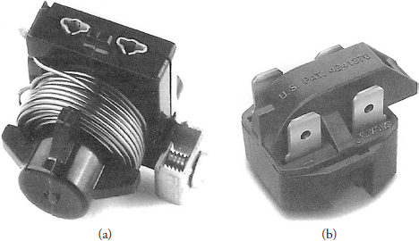
Compressor Motor Starting Relays
A hermetic motor starting relay is an automatic switching device to disconnect the motor start capacitor and/or start winding after the motor has reached running speed. There are two types of motor starting relays used in refrigeration and air conditioning applications: the current responsive type and the potential (voltage) responsive type.
Never select a replacement relay solely by horsepower or other generalized rating. Select the correct relay as specified in the Tecumseh Electrical Service Parts Guide Book.
Current Type Relay
When power is applied to a compressor motor, the relay solenoid coil attracts the relay armature upward, causing the bridging contact and stationary contact to engage. This energizes the motor start winding.
When the compressor motor attains running speed, the motor main winding current is such that the relay solenoid coil de-energizes, allowing the relay contacts to drop open and disconnecting the motor start winding.
The relay (Figure 9-10a) must be mounted in true vertical position so that armature and bridging contacts will drop free when the relay solenoid is de-energized.
FIGURE 9-10 (a) Current type relay. (b) PTC type relay.
PTC Type Relay
Solid-state technology has made available another type of current sensitive relay: a PTC starting switch (see Figure 9-10b). Certain ceramic materials have the unique property of greatly increasing their resistance as they heat up from current passing through them. A PTC solid-state starting device is placed in series with the start winding and normally has a very low resistance. Upon startup, as current starts to flow to the start winding, the resistance rapidly rises to a very high value, thus reducing the start winding current to a trickle and effectively taking that winding out of operation.
Usage is generally limited to domestic refrigeration and freezers. Because it takes 3 to 10 minutes to cool down between operating cycles, it is not feasible for short-cycling commercial applications.
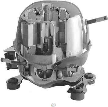
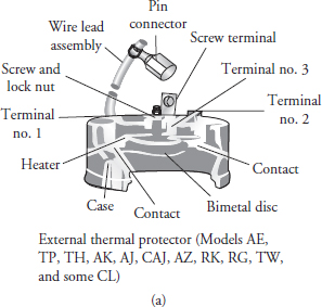
Compressor Thermal Protectors (Overloads)
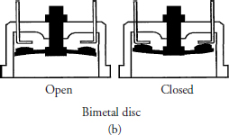
All hermetic compressors have either an internal or an external protector (overload) to protect the motor from overheating. The compressor overload in Figure 9-11a is attached to the compressor in Figures 9-11c and 9-11d. The overload is designed to react quickly by means of a bimetal disk to an increase in temperature or an increase in current.
FIGURE 9-11a The compressor overload protector.
FIGURE 9-11b An internal view of the compressor overload protector.
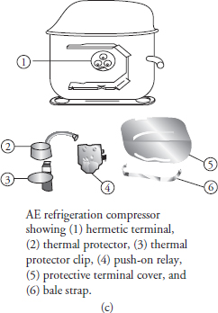
FIGURE 9-11c An illustration of the components before they are attached to the exterior of the compressor.
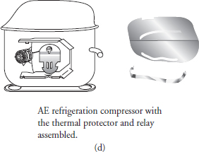
FIGURE 9-11d An illustration of the components after they are attached to the exterior of the compressor.
The bimetal disk (Figure 9-11b) consists of two dissimilar metals combined together. Any change in temperature or current draw will cause it to deflect, actuating the switch contacts. When the bimetal cools, the reverse action takes place. The external protector is a non-serviceable part, and it should be replaced with a duplicate of the original. If the compressor has an internal overload and is diagnosed as being defective, the compressor will have to be replaced by a certified technician.
Condenser Coil
A condenser coil is manufactured out of copper, aluminum, or steel tubing, with metal fins attached to the tubing to assist in dissipating the heat (Figures 9-12a and b). The main purpose of the condenser coil is to dissipate the heat from the refrigerant along with the heat from the compression stage of the compressor. Condenser coils in refrigerators, freezers, and room air conditioners usually have a fan motor and fan blade circulating the air across the condenser coil to assist in removing the heat from the refrigerant. On some models of refrigerators and freezers, the condenser coils are static-cooled whereby the heat from the condenser coil will rise and dissipate into the room. In some models of freezers, the condenser coil is attached to the inside of the outer cabinet so that the cabinet is the heat transfer medium.
FIGURE 9-12a The condenser coil in a refrigerator’s sealed refrigeration system.
FIGURE 9-12b The condenser coil in a freezer’s sealed refrigeration system.
Evaporator Coil
The evaporator coil, manufactured in the same manner as the condenser coil, absorbs the heat from the food product or from the air in a room to be cooled (Figures 9-5, 9-12a, and 9-12b). Manufacturers design evaporator coils in different shapes and designs to meet the needs of specific products. Most refrigerator models and room air conditioners use a fan motor and fan blade to circulate the air across the evaporator coil, which absorbs the heat. Other refrigerator/freezer models have rows of tubing placed between two plates, which are welded together to form an interior cabinet in the freezer compartment or shelving.
Metering Device
The most commonly used metering device in a domestic refrigerator and room air conditioner is a capillary tube, also called a cap tube (Figures 9-3, 9-4, and 9-6). This metering device is manufactured out of copper tubing, with a very small-diameter opening at both ends, and is premeasured at a specific length for maximum heat load efficiency for the product being cooled or refrigerated. The small-diameter opening in the cap tube will restrict the flow of refrigerant, causing a pressure drop from the high-pressure side (condenser) of the sealed system to the low-pressure side (evaporator). This will allow the refrigerant to enter the evaporator at the rate needed to remove the unwanted heat from the product being cooled or refrigerated. There are no moving parts in a cap tube, and it does not require any service. The capillary tube is located between the condenser coil and the evaporator coil at the end of the liquid line.
Other Components Used in the Sealed Refrigeration System
The refrigeration sealed system in an appliance or air conditioner can have additional components added to the sealed system. These additional components added are usually from manufacturers’ designs of the product. These additional components will enhance the operation of the product. Some additional components are:
• Refrigeration drier The function of the refrigerant drier (Figure 9-12a) is to trap any moisture, contaminants, and large particulate matter within the sealed refrigeration system. In a refrigerator or air conditioner, the drier is installed within the liquid line before the metering device. The drier can be either a unidirectional flow or bidirectional flow drier. The drier must be compatible with the oils and refrigerants that are used in today’s products.
• Accumulator Some models of refrigerators and freezers have accumulators (Figure 9-3b, c, and d). An accumulator is a device located at the end of the evaporator coil. Its appearance makes the tubing size look much larger. It looks like a small elongated storage tank attached to the evaporator coil. The accumulator allows liquid refrigerant to be collected in the bottom of the accumulator and stay there. Only vapor refrigerant will be drawn from the accumulator and returned to the compressor. On air conditioners, the accumulator is located on the suction line returning to the compressor. The compressor and accumulator are one component.
• Heat exchanger The heat exchanger (Figure 9-6 and Figure 9-12a) consists of the suction line soldered to the capillary tube. The reason for this is to make sure that there is good contact between the two lines. These two tubes are located inside a refrigerator or freezer. There are two purposes for the heat exchanger:
1. The capillary tube will give up some of its heat to the cooler suction line, thus allowing the refrigeration system to run more efficiently.
2. No liquid refrigerant will be allowed to return to the compressor. The warmer refrigerant in the capillary tube will boil off and vaporize any remaining liquid refrigerant in the suction line.
Diagnosing Sealed Systems
When servicing the refrigerator/freezer or room air conditioner, do not overlook the simple things that might be causing the problem. Before you begin testing and servicing an appliance or air conditioner, check for the most common faults. Inspect all wiring connections for broken or loose wires. Check and see if all components are running at the proper times during the cycle. Test the temperatures in the refrigerator/freezer cabinet or air conditioner inlet and outlet grills.
The following charts (Tables 9-4 and 9-5) is intended to serve as an aid to assist the technician in determining if there is a sealed system malfunction, providing that all other components are functioning correctly within the appliance or conditions that mimic a sealed system failure. You must rule out everything else before you enter the sealed system.
NOTE Before you enter a sealed system, you must be certified to do so.
TABLE 9-4 Refrigeration Sealed-System Diagnosis Chart
TABLE 9-5 Conditions that Mimic a Sealed System Failure