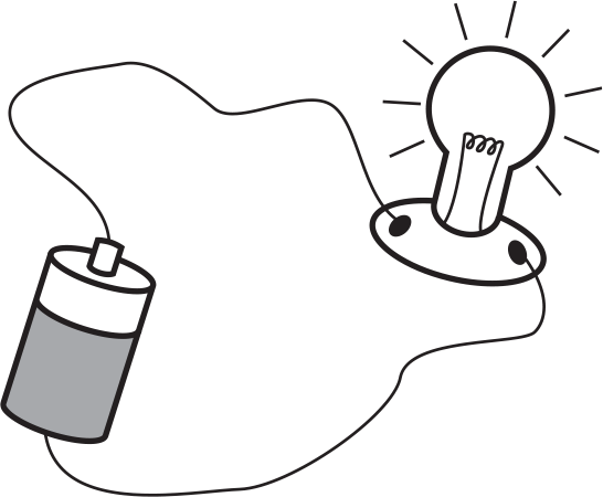
When we connect a battery, wires, and a light bulb in the circuit shown below, the bulb lights up. But what is actually happening in the circuit?
Recall from the previous chapter that the battery has a potential difference, or voltage, across its ends. One end of the battery is positive, and the other end is negative. When we connect the wires and light bulb to the battery in a complete circuit, charge begins to flow from one end of the battery, through the wires and the bulb, to the other end of the battery, causing the bulb to light. We say that the movement of positive charge from the positive end of the battery through the circuit to the negative end of the battery is called conventional current, or simply current. Current is the amount of charge moving through a conductor per second, and the unit for current is the coulomb/second, or ampere. We use the symbol I for current.
Technically speaking, it is (generally) negative charges and not positive charges that move through a circuit (although it is conventional to speak of positive charge flowing rather than negative charge flowing). When the battery is connected to the circuit, an electric field is set up such that the negative charges experience a force that push them in one direction through the wire. At the same time, positive charges experience a force in the opposite direction, but since the electrons that comprise the negative charge in matter are much more mobile than those particles (protons) that comprise the positive charge, it is actually the electrons (and not the positive charge) that are moving through the circuit. As the electrons move through the light bulb filament, they generate heat and light that causes the light bulb filament to glow. The SAT Subject Test: Physics generally uses the conventional current model of positive charge current flow in the direction of the motion of positive charges.
As charge moves through the circuit, it encounters resistance, or opposition to the flow of current. Resistance is the electrical equivalent of friction. In our previous circuit diagram, the wires and the light bulb would be considered resistances, although usually the resistance of the wires is neglected. When a larger voltage is used, more charge moves through the wire, and thus more current flows through the circuit. In other words, the current is directly proportional to the voltage. This implies that the ratio of voltage to current is a constant. This constant is defined as the resistance, and is measured in ohms (Ω). An ohm is a volt/amp. The relationship between voltage, current, and resistance is called Ohm’s law:

This relationship typically holds true for the purposes of the SAT Subject Test: Physics.
Table 12.1 below summarizes the quantities discussed so far.
| Quantity | Symbol | Unit | Schematic Symbol |
| Battery voltage | V | Volts (V) |

|
| Current | I | Amps (A) |

|
| Resistance | R | Ohms (Ω) |

|
Usually, when we draw circuit diagrams, we use the symbols in the table above. For example, the simple light bulb circuit would look like the following diagram.

If we wanted to actually measure the current through the resistor and the voltage across the resistor, we would connect an ammeter (to measure current) in series with the resistor, and a voltmeter (to measure voltage) in parallel with the resistor, as shown below.

We place the ammeter in series with the resistor so that the same current will pass through the ammeter and the resistor, and we place the voltmeter in parallel with the resistor so that the voltage will be the same across the voltmeter and the resistor. Ammeters have a low resistance so as not to add to the total resistance of the circuit (and thus decrease the current in the circuit), and voltmeters have a high resistance so that current will not want to flow through them and bypass the resistor.