Using the gyro sensor, the robot will move in a series of motions to follow a square or avoid an obstacle.
The following steps explain how to attach the gyro sensor to our robot:
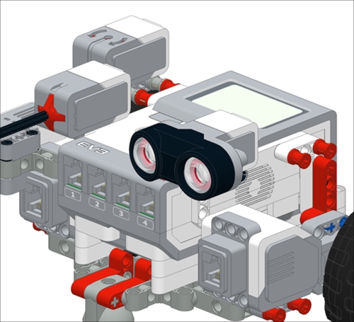
- First, take two axles which are three modules long with stops and attach them to the gyro sensor with bushings as shown in the following figure:

- Next, we will attach the gyro sensor to the two red stop bushings on the back of the robot. We can wire the gyro sensor to Port 4 on our EV3 brick.
Make the robot go forward, turn until the gyro says it has turned 90 degrees, go forward, and repeat this sequence several times.
- We will first use a
Loop Flowblock and select theCOUNTmode for the loop block. We can make the robot repeat this turning sequence several times. - Inside this loop the robot will move forward for one rotation of the wheels.
- Move while steering until the
Waitblock is triggered by a change in state of the gyro sensor by 90 degrees.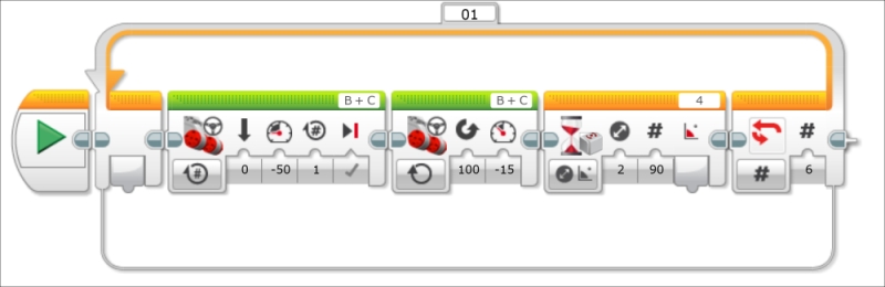
- Before you run the program, you need to make sure that the robot is stationary. It is critical to reset the gyro sensor by unplugging it and plugging it back in while the robot is stationary. We can now run this program. If you notice that your gyro values keep changing even though the robot is not moving, this means the gyro needs to be reset.
The gyro sensor detects rotational motion. You can use it to measure the angle or the angular speed. Using the gyro sensor will allow you to quickly make accurate turns. Without a gyro sensor, you would have to navigate using a technique called dead reckoning. This consists of mapping the turning of your robot by using the build-in shaft encoders on the wheels.
The gyro will drift over time, so it is a good idea to reset the gyro when using it in your programs. Including both a Reset Gyro block and unplugging the hardware are good ideas when using the gyro sensor.
You will notice that using this simple code, the robot does not make a perfect square. This is because you are asking the robot to stop exactly at the 90 degree signal, by which time it is too late because of the inertia of the robot. In the remaining recipes, we will optimize the motion of the robot and program the robot to steer around obstacles.
To diagnose why the robot is not turning in a perfect square, we will alter our previous program by making the robot display on the screen what angle the gyro is currently reading. First, start out by clearing the EV3 display screen with a Display block. Make sure you set the Display block to Text and replace the word Mindstorms with an empty space. This is followed by the Reset Gyro block. Inside the loop, add a Move block set to stop, and a Wait block (for 2 seconds) to allow you time to read the angle. Place a Display block set to Text Grid mode with the Erase input unselected. Draw a wire from the Angle output of the Wait Gyro block to the Text input of the Display block. Although the Wait block is acting upon changes in 90 degrees, it will send the actual angle measurement. The displayed text will overlap. We can control the placement of text on the screen using the index counter of our loop. Create a Math block which will multiply numbers by 2. Run a wire from the Loop Index block to the Math block. Run a wire from the output of the Math block to the Y-coordinate input of the Display block. As the loop runs through subsequent iterations, the index increases and so will the placement of text on the display screen. This process is illustrated in the following screenshot:
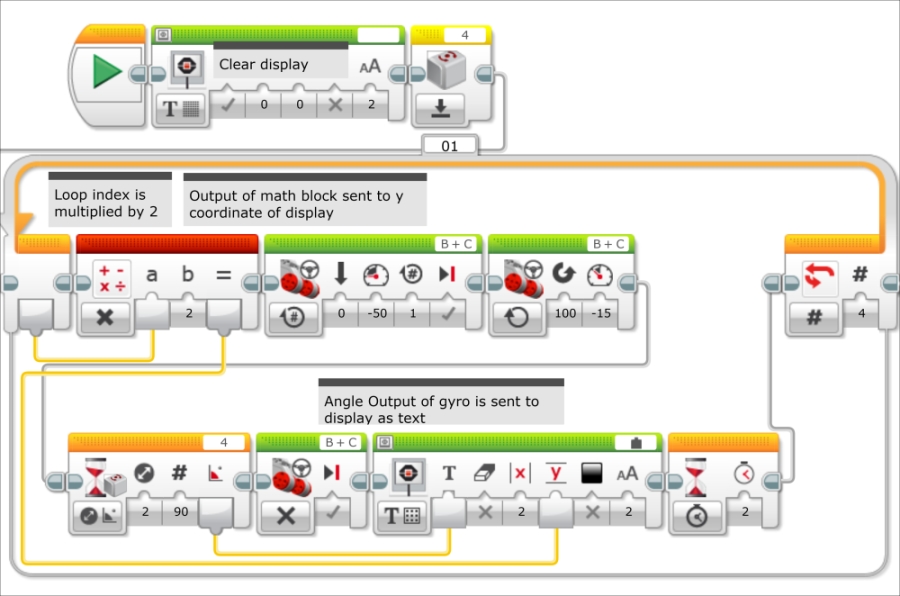
When you look at the numbers on the brick display, you will find that on each turn, the robot is overshooting the turn. This is because the robot does not begin stopping until it reaches 90 degrees. And as it overshoots each turn, these errors build on each other to create a path which is anything but a perfect square.
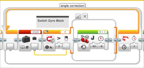
We will now use a case structure to add a correction to the turns. In the EV3 language, a case structure, or if-then statement is called a Switch Flow block. The Switch can be controlled by the sensors' other logic statements. Although you typically will have only two cases, you could add several other branches to the case structure. Each branch of the switch is called a case statement and can consist of several programming blocks. We will use the gyro sensor to define the case to try and zigzag onto the exact 90 degree angle. In the next screenshot you can see the entire code:
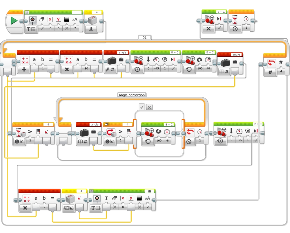
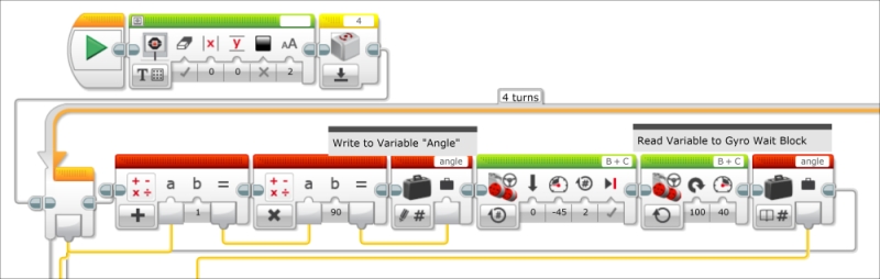
Initially, we asked the gyro sensor to wait only when it had turned 90 degrees on each leg of our square. Now we will adjust our code to ask the robot to stop turning when it reaches 90, 180, 270, and 360 degrees. We will do this by using a Variable block set to write numeric mode. We will give this Variable block the name Angle. The index counter on the loop runs through the sequence 0, 1, 2, and 3. We will use two math functions to come up with these degrees. Run a wire from the Index Counter block to a Math block set to math mode and add 1 to each number. The output of the add Math block should go to a Math block set to multiply mode. This number should be multiplied by 90 and the output should be sent to the Variable block. After the Move Steering block, the Wait Gyro block will be triggered when the sensor reads an angle greater than the Variable block as shown in the following screenshot:
This brings us to the Switch block. The Switch block will have two cases defined by readings from the gyro sensor. If the gyro sensor has a reading greater than the output of the Variable block, it will follow Case 1, which contains a Move Steering block, which is set to the left. If the gyro sensor has a reading less than or equal to the output of the Variable block, it will follow Case 2, which contains a Move Steering block, which is set to the right.
We will allow this correction to repeat itself several times by placing it inside a Loop Flow block which will repeat the decision making for two seconds. The result will be a zigzag motion approaching the exact angle as shown in the following screenshot:
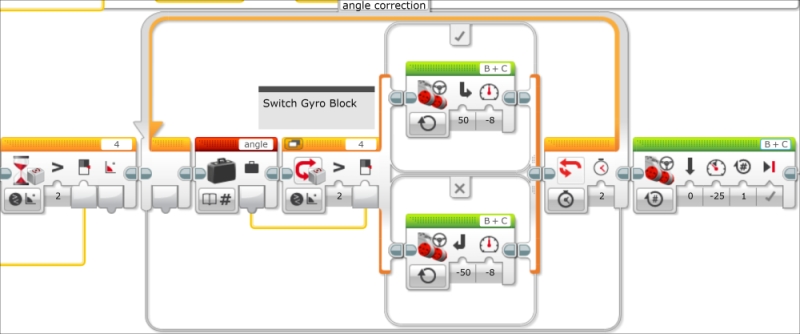
The previous screenshot has an expanded view showing both cases of the switch. You can also use a tabbed view of the switch. The next screenshot shows the positive case:
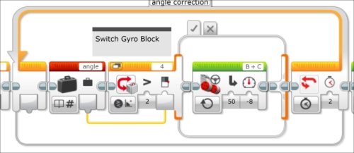
The next screenshot shows the negative case of the switch:
We are using a somewhat logic based decision to turn and hoping to get as close as possible, which gives a chaotic zigzag motion. We should use a proportional algorithm, which would slow the robot down as it approaches 90 degrees. We will explore proportional algorithms in the Ultrasonic motion sensing recipe.
In this section we will program the robot to move forward until it encounters an unknown obstacle with the touch sensor and then attempt to steer around the obstacle. An obstacle such as a table or chair leg would be ideal. We will program the robot to take input from the brick buttons. The program we will initially write is inefficient and repetitive. It is actually a good example of how you shouldn't write a program. Remember, you should be able to view your entire code all at once. We will simplify the code using the EV3 version of a subroutine called MyBlock.
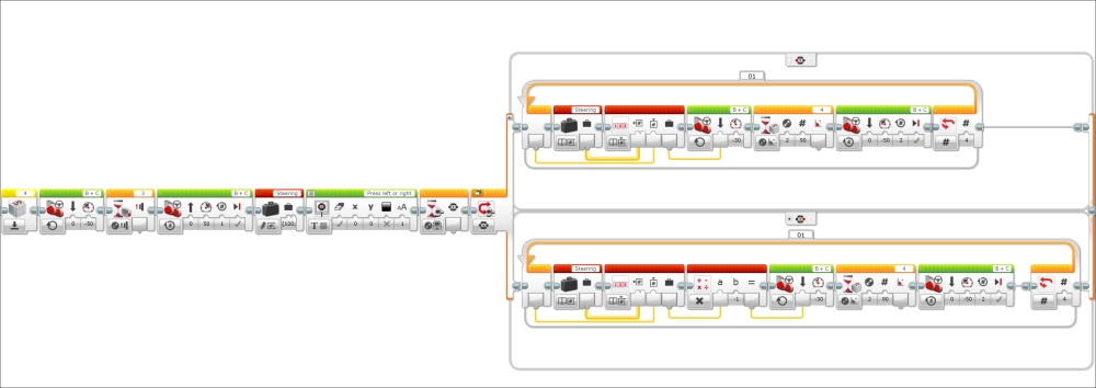
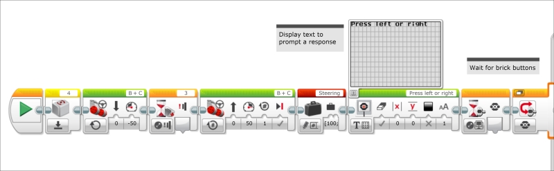
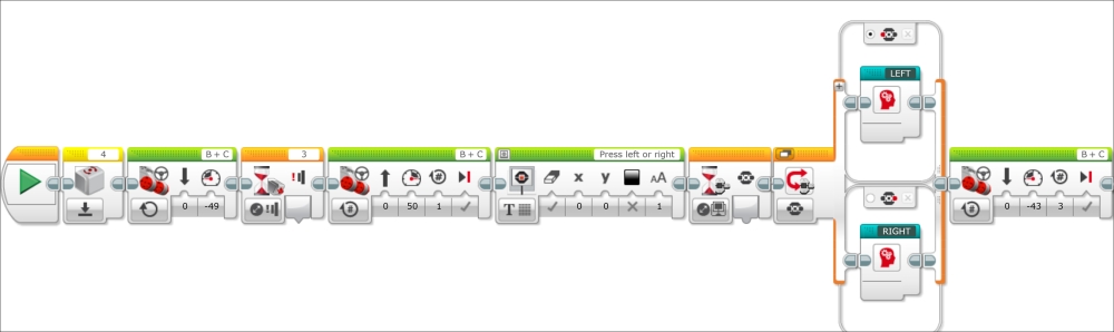
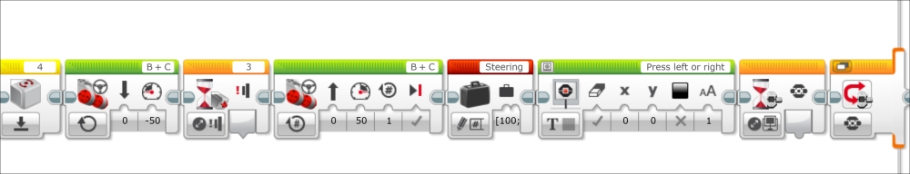
We will start a new program by resetting the gyro sensor. The robot will then move forward until the Wait block is triggered by a change in the state of the touch sensor. We will then program the robot to move back for one rotation of the wheels and display the following message onto the brick screen Press left or right. The next Wait block will wait for the user to press one of the brick buttons on the EV3 brick. This will be followed by a case structure or the Switch Flow block as shown in the following screenshot:
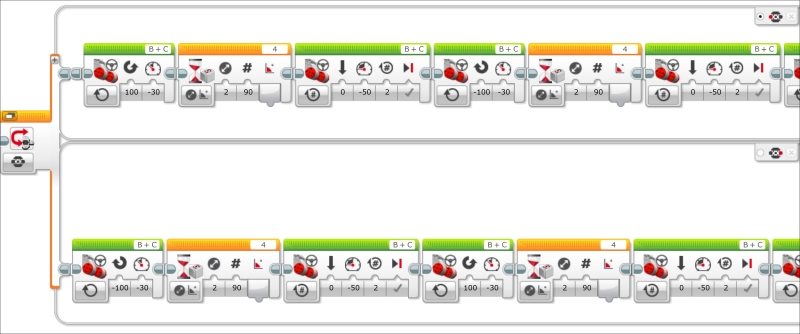
The Switch Flow block has two cases, one if the left brick button is depressed, and the other if the right brick button is depressed. The user will determine if they want the robot to avoid the obstacle by taking a detour to the left or right of the obstacle. Each case structure contains eleven blocks. The robot turns until triggered by the gyro, moves, turns, moves, and so on. The sequence is so long, that we cannot even view the entire code on one screen:
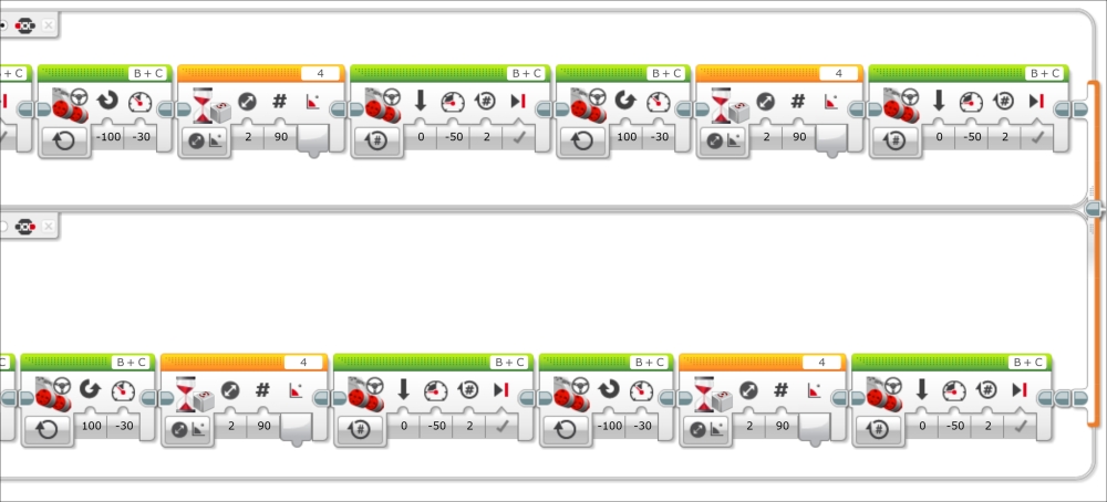
Here is the second part of the code:
At this point, we can download and execute the code and the robot should be able to steer around a small rigid object.
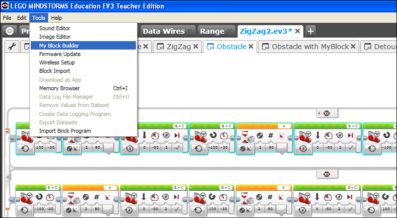
We can now simplify the code using a MyBlock or a subroutine. Select all of the blocks inside one branch of the case structure. You will know the blocks have been selected because they will be highlighted with a light blue perimeter. Then, under the Tools drop- down menu select My Block Builder:
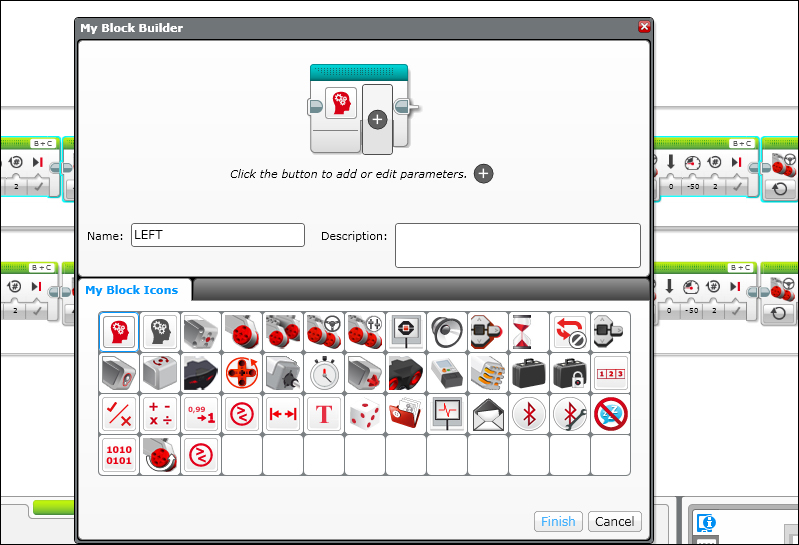
The My Block Builder screen (as shown in the previous screenshot) will pop up and ask you to name the MyBlock which is akin to naming a subroutine. You can also write a description and select an icon. You can also design an icon. You might also notice that the MyBlock can be modified to accept parameters. For our first introduction to the MyBlock, we will just use it to simplify the code. In the Ultrasonic motion sensing recipe, we will cover MyBlocks in more detail. We will name this MyBlock, LEFT.
You should do the same for the other branch of the case structure (or switch), but instead, name that MyBlock, RIGHT. After you have defined a MyBlock, you can find it in the Programming Palette under the commands in the light blue programming blocks tab which you can see at the bottom of the next screenshot:
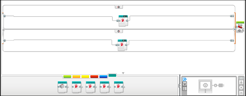
At this point, we can clean up the code by deleting a lot of the empty space which has been created inside the Switch block. We can now download and execute this simplified code:
In the previous section, we saw how to simplify the program to avoid an obstacle using a MyBlock (subroutine). In this section, we will optimize the program using an array instead. To learn how an array in EV3 works, we will first write a program to display a series of numbers on the EV3 brick screen.
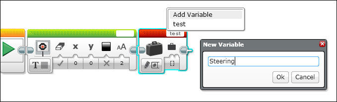
First, clear the display screen. Then define a variable called Steering. Instead of writing to a numeric variable, we are going to write to an array. The difference between a variable and an array is that a variable only contains one value or element, whereas an array can contain several values or elements. This is illustrated in the following screenshot:
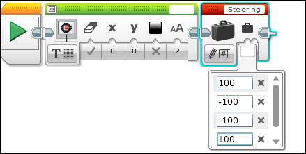
We will write the series of numbers [100, -100, -100, 100] into the array as shown in the following screenshot. This will be useful later when we use this same write variable block in the obstacle code.
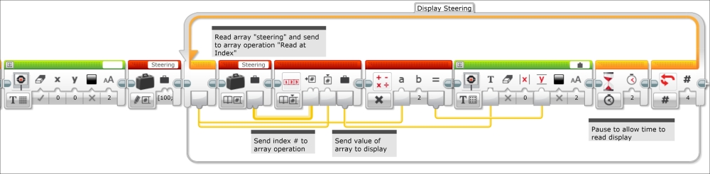
We will now create a loop called Display Steering which will repeat four times. The first block in our loop will be the read array variable block. It will then send via a wire the information from the variable steering block into an array operation block. We will also run a wire from the loop index into the array operation. This will allow us to read a different element in the array every iteration of the loop. This element will be sent as text to the display screen via a wire. Remember to uncheck that the display will not erase each time it runs. Again, the Y-coordinate location on the display screen is increased by a multiple of the loop index. When you run this program, you should see the elements of the array displayed in a column on the brick screen every two seconds. This is illustrated in the following screenshot:
Now we are going to use an array to modify the obstacle code we wrote in the previous section. You will need to add the write array variable block in the beginning of the program before the case structure.
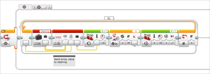
Replace the code you had previously written in the left button case structure with the following blocks. First, place a loop which will run for 4 counts into the case structure. Next, send the output from a read array variable block to an array operation block. Also, run a wire from the loop index block to the array operation block. We will run a wire from the array operation block output to the move steering block direction input. The array is telling the robot which direction to turn. Remember, the array contains the elements [100, -100, -100, 100]. If the program chooses the first or last elements, then the steering value is to the left. If the program chooses the second or third elements, then the steering value is to the right. During each loop, the element which is chosen is determined by loop index. The robot will turn until the Wait Gyro block reaches 90 degrees. The robot will then move forward for two rotations of the wheels and the loop will repeat. This is illustrated in the following screenshot:
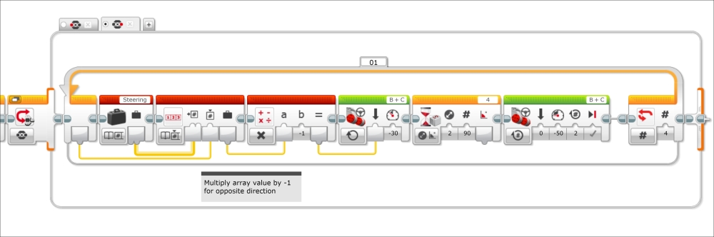
The other side of the case structure (resulting when the right button is pushed) has a similar code. We can modify the direction of the robot by adding a Math block, which will send the opposite value of the array elements to the Move Steering block. This is illustrated in the following screenshot:
We will find that it is possible to view the entire optimized program on one screen: