In this recipe, you will make a robot that will track a line quickly. The robot will be able to follow a line which makes corners sharper than 90 degrees using a proportional line follower.
First, you will need to build an attachment to hold the color sensor onto the robot.
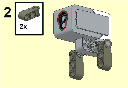
Insert an axle that is five modules long into the color sensor. Place bushings onto the axle on either side of the sensor. This is illustrated in the following figure:

Attach the two-pin one-axle cross blocks onto the axle outside the bushings. This is illustrated in the following figure:
Insert 3-module pins into the cross blocks as shown in the following figure:
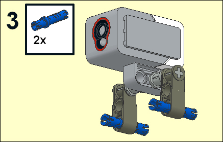
The pins will attach to the robot just in front of the castor. The bottom of the color sensor should be approximately leveled with the plastic part of the castor holder. If you are on a flat hard surface, your light sensor will be half a centimeter above the ground. If you are on a soft surface, you may need to add a spacer to raise up the sensor. This is illustrated in the following figure:

We are going to write a proportional line following code similar to the code used for the ultrasonic motion sensor.
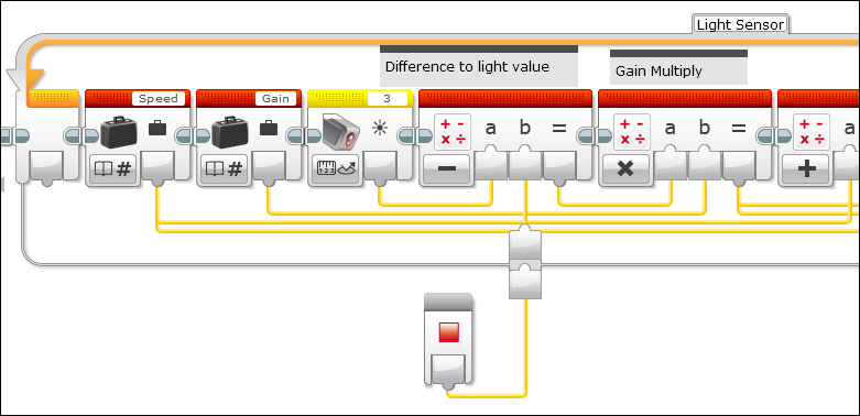
- We will write the following code:

- This program contains a loop so the robot will track a line for 30 seconds.
- The base speed of the robot is controlled by a constant value which in this case, is 15.
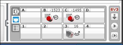
- You will need to determine a desired light sensor value for the robot to track on. You can either read the light sensor reading directly on your EV3 brick, or look at the panel on the lower-right hand corner of your screen. You should see all of the motors and sensors that are currently plugged into your brick. In the following screenshot, the current light sensor reading is 16.
- When tracking a line, you actually want to track on the edge of a line. Our code is designed to track on the right edge of a black line on a white surface. The line doesn't have to be black (or a white surface), but the stronger the contrast the better. One way to determine the desired light sensor value would be to place the light sensor on the edge of the line.
- Alternatively, you could take two separate readings on the bright surface and the dark surface and take the average value.
- In the code we discussed, the average value is 40, but you will have to determine the values which work in your own environment. Not only will the surfaces affect the value, but ambient room light can alter this value.
- The code next finds the difference between the desired value and the sensor reading.
- This difference is multiplied by a gain factor, which for the optical proportional line follower will probably be between 0 and 1. In this program, I chose a gain of 0.7.
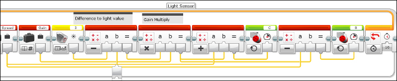
- The result is added to the base speed of one motor and subtracted from the based speed of the other motor:

- After taking the light sensor readings, practice with several numbers to figure out the best speeds and proportionality constants to make your robot follow a line.
This algorithm will make corrections to the path of the robot based on how far off from the line the robot is. It determines this by calculating the difference between the light sensor reading and the value of the light sensor reading on the edge. Each wheel of the robot rotates at a different speed proportional to how far from the line it is. There is a base speed for each wheel and then they will go either slower or faster for a smooth turning. You will find that a large gain value will be needed for sharp turns, but the robot will tend to overcorrect and wobble when it is following a straight line. A smaller gain and higher speed can work effectively when the line is relatively straight or follows a gradual curve. The most important factor to determine is the desired light sensor value.
Although your color sensor can detect several colors, we will not be using that feature in this program. The color sensor included in your kit emits red light and we are measuring the reflection of that reflected light. The height of the sensor above the floor is critical, and there is a sweet spot for line tracking at about half a centimeter above the floor. The light comes out of the sensor in a cone. You want the light reflected into the sensor to be as bright as possible, so if your sensor is too high, the reflected intensity will be weaker. Assuming your color sensor is pointing straight down at the floor (as it is in our robot design), then you will see a circular red spot on the floor. Because the distance between the detector and the light emitter is about 5 to 6 mm, the diameter of this circle should be about 11 mm across. If the circle is large, then your color sensor is too high and the intensity will weaken. If the circle is smaller than this, then the sensor will not pick up the emitted light.
The color sensor in the LEGO MINDSTORMS EV3 kit is different from the optical sensors included in the earlier LEGO NXT kits. Depending on your application, you might want to pick up some of the older NXT lights and color sensors. The light sensor in the NXT 1.0 kit could not detect color and only measured reflected intensity of a red LED. What is good about this sensor is that it will actually work flush against the surface and saves the need to calibrate changes due to the ambient lighting conditions. The color sensor in the NXT 2.0 kit actually emitted colored lights and contained a general photo detector. However, it did not directly measure color, but measured the reflection of colored light, which it would emit. This actually allowed you to track along different colored lines, but it was also slower. The new EV3 sensor detects colors directly, works quickly, and emits only red light.
How can you adjust the algorithm to adjust the response of the robot to follow the line faster or smoother, depending on the shape of the line without needing to change your program?
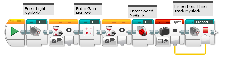
We will use several MyBlocks to allow us to enter values for the light sensor reading, gain, and speed right on the robot. We will also have a separate MyBlock for a modified Proportional Tracker code. After you have first written the MyBlocks, you can write the following code to track a line. This is illustrated in the following screenshot:
The first MyBlock will allow us to enter a value for the light reading. This MyBlock is similar to what we wrote in the previous recipe for entering a value on the brick. Notice that in the display we ask the reader for a Light value, and the variable is now called Light. A starting value of 30 will probably be a good edge sensor reading for most applications.
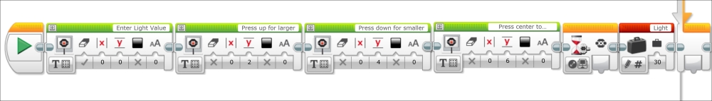
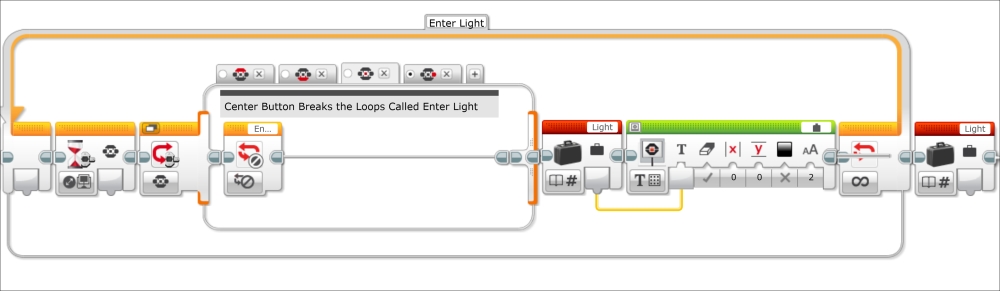
The loop is now called Enter Light. For the case structure contained Loop Interrupt, make sure it refers to the correct Loop. Also, notice all of the variables we refer to are called Light. This is illustrated in the following screenshot:
Using increments of 1 to increase or decrease the light sensor value will still work:

In the next screenshot, you can better see how the Down button subtracts 1 from the value of the variable:

Do not forget that our Switch still needs a fourth case structure for the default value. This is illustrated in the following screenshot:

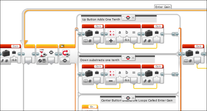
You will write a similar MyBlock for entering a gain value. Note that the names of the variables are different as are the names of the loops and Loop Interrupt. Also, for this MyBlock it is appropriate to increase or decrease the gain multiplier by one tenth. This is illustrated in the following screenshot:
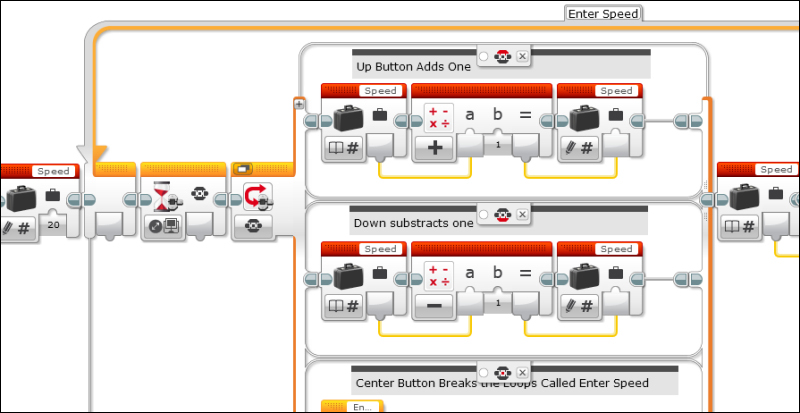
The third MyBlock for this program will select the seed. Again, remember the change in the variables and loop names. This is illustrated in the following screenshot:
The Proportional MyBlock is a bit more complex than the code we wrote at the beginning of this recipe. In our program at the beginning of this recipe, if you wanted to change a light value, you had to change it in the computer program itself. The MyBlock will accept the Light variable from an external parameter which will be useful later in this recipe. The new program will allow you to change light values using the EV3 brick buttons. We now find the difference between the light sensor reading and the external parameter defined by our desired light reading. This difference is multiplied by the Gain variable. We then add or subtract this to/from the Speed variable. The next screenshot has the first five commands in this loop:
The next screenshot has the remaining commands in this loop where the values are sent to the motor blocks:
Now are going to calibrate the robot by placing the robot on the edge of line and saving that information to a file. Create a MyBlock from the following code. This takes a light sensor reading and saves it to the file light.

Now our main program contains this new MyBlock. Instead of reading the light variable, it reads the value stored in the file as illustrated in the next screenshot:

The program in the Calibrating the light sensor values section assumes you have your robot placed right on the edge of the line. Alternatively, we could take calibration readings on the bright and dark areas. In the following MyBlock, the readings from two measurements are averaged. This means you will have to move the robot around by hand. This is illustrated in the following screenshot:

Our main program now takes the average value created by this new MyBlock and feeds it to the Proportional Controller.

In this recipe, you have learned to develop a proportional line controller using one light sensor. Without changing the code, using buttons on the robot you can change the execution parameters. An additional challenge could be to have the robot rotate and scan for these two values. You could also use more than one light sensor.