13
IoT and Edge Security
The first chapter of this book revealed the size, growth, and potential of the Internet of Things (IoT). There are currently billions of devices, and the double-digit growth of connecting the analog world to the Internet also forms the largest attack surface on Earth. Exploits, damage, and rogue agents have already been developed, deployed, and spread globally, disrupting countless businesses, networks, and lives. As architects, we are responsible for understanding the IoT stack of technologies and securing them. As we place devices that have never been connected to the Internet, as good citizens, we are accountable for designing them.
This has been particularly difficult for many IoT deployments, with security often being thought of last. Frequently, systems are so constrained that building enterprise-level security that modern web and PC systems enjoy is difficult if not impossible on simple IoT sensors. This book also talks about security after all other technologies have been understood. However, every chapter has touched on the provisions of security at each level.
This chapter will explore some particularly heinous IoT-focused attacks and give thought to how weak security is in IoT and how much damage can be done. Later, we discuss the security provisions at each level of the stack: physical devices, communication systems, and networks. We then address software-defined perimeters and blockchains used to secure value in IoT data. The chapter wraps up by examining the United States Cybersecurity Improvement Act of 2017 and what it could mean for IoT devices.
The most important thing in security is to use it at all levels from the sensor to the communication system, router, and cloud.
Cybersecurity vernacular
Cybersecurity has an associated set of definitions describing different types of attacks and provisions. This section briefly covers the jargon of the industry as presented in the rest of this chapter.
Attack and threat terms
The following are the terms and definitions of different attacks or malevolent cyber threats:
- Amplification attack: Magnifies the bandwidth sent to a victim. Often an attacker will use a legitimate service such as NTP, Steam, or DNS to reflect the attack upon a victim. NTP can amplify 556x, and DNS amplification can escalate the bandwidth by 179x.
- ARP spoof: A type of attack that sends a falsified ARP message resulting in linking the attacker's MAC address with the IP of a legitimate system.
- Banner scans: A technique typically used to take inventory of systems on a network that can also be used by an attacker to gain information about a potential attack target by performing HTTP requests and inspecting the returned information of the operating system (OS) and computer (for example,
nc www.target.com 80). - Botnets: Internet-connected devices infected and compromised by malware working collectively by common control, mostly used in unison to generate massive DDoS attacks from multiple clients. Other attacks include email spamming and spyware.
- Brute force: A trial-and-error method to gain access to a system or bypass encryption.
- Buffer overflow: Exploits a bug or defect in running software that simply overruns a buffer or memory block with more data than allocated. This overrun can write over other data in adjacent memory addresses. An attacker can lay malicious code in that area and force the instruction pointer to execute from there. Compiled languages such as C and C++ are particularly susceptible to buffer overflow attacks since they lack internal protection. Most overflow bugs are the result of poorly constructed software that does not check the bounds of input values.
- C2: Command and control server that marshals commands to botnets.
- Correlation power analysis attack: Allows one to discover secret encryption keys stored in a device through four steps:
- Examine a target's dynamic power consumption and record it for each phase of the normal encryption process.
- Next, force the target to encrypt several plaintext objects and record their power usage.
- Next, attack small parts of the key (subkeys) by considering every possible combination and calculating the Pearson correlation coefficient between the modeled and actual power.
- Finally, put together the best subkey to obtain the full key.
- Dictionary attack: A method of gaining entry to a network system by systematically entering words from a dictionary file containing the username and password pairs.
- Distributed denial-of-service (DDoS): An attack attempting to disrupt or make an online service unavailable by overwhelming it from multiple (distributed) sources.
- Fuzzing: An attack that consists of sending malformed or nonstandard data to a device and observing how the device reacts. For example, if a device performs poorly or shows adverse effects, the fuzz attack may have exposed a weakness.
- Man-in-the-middle attack (MITM): A common form of attack that places a device in the middle of a communication stream between two unsuspecting parties. The device listens, filters, and appropriates information from the transmitter and retransmits selected information to the receiver. A MITM may be in the loop acting as a repeater or can be sideband listening to the transmission without intercepting the data.
- NOP sleds: A sequence of injected NOP assembly instructions used to "slide" a CPU's instruction pointer to the desired area of malicious code. It is usually part of a buffer overflow attack.
- Replay attack: A network attack, also known as a playback attack, where data is maliciously repeated or replayed by the originator or an adversary who intercepts the data, stores the data, and transmits it at will.
- RCE exploit: Remote code execution that enables an attacker to execute arbitrary code. This usually comes in the form of a buffer overflow attack over HTTP or other network protocols that injects malware code.
- Return-oriented programming (ROP) attack: A difficult security exploit an attacker may use to potentially subvert protections with nonexecuting memory or executing code from read-only memory. If an attacker gains control of a process stack through a buffer overflow or some other means, they may jump to legitimate and unchanged sequences of instructions already present. The attacker looks for sequences of instructions to call gadgets that can be pieced together to form a malevolent attack.
- Return-to-libc: A type of attack that starts with a buffer overflow where the attacker injects code to jump to libc or other popularly used libraries in the processes' memory space in an attempt to call system routines directly. Bypasses the protection offered by non-executable memory and guard bands. This is a specific form of ROP attack.
- Rootkit: Typically, malicious software (although often used to unlock smartphones) used to enable other software payloads to be undetectable. Rootkits use several targeted techniques such as buffer overflows to attack kernel services, hypervisors, and user mode programs.
- Side-channel attack: An attack used to gain information from a victim's system by observing the secondary effects of the physical system rather than finding runtime exploits or zero-day exploits. Examples of side-channel attacks include correlation power analysis, acoustic analysis, and reading data residue after it has been deleted from memory.
- Social engineering: As it pertains to information security, a form of attack based on psychological manipulation and personal deception to obtain private information.
- Spoofing: Malicious party or device impersonates another device or user on a network.
- SQL injection: A form of attack intent on destroying database contents. It is used upon databases using structured query language (SQL) statements.
- SYN flood: Occurs when a host sends a TCP:SYN packet that a rogue agent will spoof and forge. This will cause the host to create half-open connections to many nonexistent addresses causing the host to exhaust all resources.
- XSS: A vulnerability, also called cross-site scripting, in web applications where attackers inject client-side scripts. It was the most prevalent form of information attacks up until 2007.
- Zero-day exploits: Security defects or bugs in commercial or production software unknown to the designer or manufacturer.
Defense terms
The following are the terms and definitions of different cyber defense mechanisms and technologies:
- Address space layout randomization (ASLR): A defense mechanism that protects memory and thwarts buffer overflow attacks by randomizing where an executable is loaded in memory. A buffer overflow injecting malware cannot predict where it will be loaded in memory, thus manipulating the instruction pointer becomes extremely challenging. Protects against return-to-libc attacks.
- Black hole (sinkhole): Defends against DDoS attacks. After detecting a DDoS attack, routes are established from the affected DNS server or IP address to force rogue data to a black hole or a nonexistent endpoint. Sinkholes perform further analysis to filter out good data.
- Data Execution Prevention (DEP): Marks an area as executable or non-executable. This prevents an attacker from running code maliciously injected into such a region via a buffer overflow attack. The result is a system error or exception.
- Deep packet inspection (DPI): A method of inspecting each packet (data and possibly header information) in a data stream to isolate intrusions, viruses, spam, and other criteria being filtered.
- Firewall: A network security construct that grants or rejects network access to packet streams between an untrusted zone and a trusted zone. Traffic can be controlled and managed through access control lists (ACLs) on routers. Firewalls can perform stateful filtering and provide rules based on destination ports and traffic state.
- Guard bands and non-executable memory: Protects regions of memory that are writeable and not executable. Protects against NOP sleds. Intel: NX bit, ARM XN bit.
- Honeypots: Security tool to detect, deflect, or reverse engineer malicious attacks. Honeypots appear as legitimate websites or accessible nodes in a network but are actually isolated and monitored. Data and interactions with the device are logged.
- Instruction-Based Memory Access Control: A technique to separate the data portion of a stack from the return address portion. This technique helps protect against ROP attacks and is particularly useful in constrained IoT systems.
- Intrusion detection system (IDS): A network construct to detect threats in a network through the out-of-band analysis of the packet stream; therefore, not inline with the source and destination so as to affect real-time response.
- Intrusion prevention system (IPS): Blocks threats to a network via true inline analysis and statistical or signature detection of threats.
- Milkers: A defensive tool that emulates an infected botnet device and attaches to its malevolent host allowing one to understand and "milk" the malware commands being sent to the controlled botnet.
- Port scanning: A method to find an open and accessible port on a local network.
- Public key: A public key is generated with a private key and is accessible to external entities. A public key can be used to decrypt hashes.
- Public key infrastructure (PKI): Provides a definition of hierarchies of verifiers to guarantee the origin of a public key. A certificate is signed by CAs.
- Private key: Generated with a public key, never released externally, and stored securely. It is used to encrypt hashes.
- Root of Trust (RoT): Starts execution on a cold booting device from an immutable trusted source of memory (such as ROM). If early boot software/BIOS can be changed without control, then no RoT exists. The RoT is usually the first phase in a multiphase secure boot.
- Secure boot: A series of boot steps for a device that starts at a RoT and proceeds through OS and application loading where each component signature is verified as authentic. Verification is performed through public keys loaded at previous trusted boot stages.
- Stack canaries: Guards process stack space from stack overruns and prevents the execution of code from a stack.
- Trusted execution environment (TEE): A secure area of a processor that ensures code and data residing within this zone is protected. This is usually an execution environment on the main processor core where the code for secure booting, monetary transfers, or private key handling will be executed with a higher level of security than the majority of the code.
Anatomy of IoT cyber attacks
The area of cybersecurity is a broad and massive topic beyond the scope of this chapter. However, it is useful to understand three types of IoT-based attacks and exploits. Since the topology of the IoT consists of hardware, networking, protocols, signals, cloud components, frameworks, operating systems, and everything in between, we will now detail three forms of prevalent attacks:
- Mirai: The most damaging DoS attack in history, which spawned from insecure IoT devices in remote areas.
- Stuxnet: A nation-state cyber weapon targeting industrial SCADA IoT devices controlling uranium enrichment centrifuges and causing substantial and irreversible damage to Iran's nuclear program.
- Chain Reaction: A research method to exploit PAN using nothing but a lightbulb—no Internet needed.
By understanding the behaviors of these threats, the architect can derive preventative technologies and processes to ensure similar events are mitigated.
Mirai
Mirai is the name of malware that infected Linux IoT devices in August of 2016. The attack came in the form of a botnet that generated a massive DDoS storm. High-profile targets included Krebs on Security, a popular Internet security blog; Dyn, a very popular and widely used DNS provider for the Internet; and Lonestar cell, a large telecom operator in Liberia. Smaller targets included Italian political sites, Minecraft servers in Brazil, and Russian auction sites. The DDoS on Dyn had secondary effects on other extremely large providers that used their services, such as Sony Playstation servers, Amazon, GitHub, Netflix, PayPal, Reddit, and Twitter. In total, 600,000 IoT devices were infected as part of the botnet collective.
Mirai source code was released on hackforums.net (a hacker blog site). From the source and through traces and logs, researchers have uncovered how the Mirai attack worked and unfolded:
- Scan for victims: It first performed a rapid asynchronous scan using TCP SYN packets to probe random IPV4 addresses. It specifically looked for SSH/Telnet TCP port 23 and port 2323. If the scan and port attached successfully, it entered phase two.
Mirai included a hardcoded blacklist of addresses to avoid. The blacklist consisted of 3.4 million IP addresses and contained IP addresses belonging to the US Postal Service, Hewlett-Packard, GE, and the US Department of Defense. Mirai was capable of scanning at about 250 bytes per second. This is relatively low as far as a botnet is concerned. Attacks like the SQL Slammer generated scans at 1.5 Mbps, the principle reason being that IoT devices typically are much more constrained in processing power than desktop and mobile devices.
- Brute force telnet: At this point Mirai attempted to establish a functional Telnet session with a victim by sending 10 username and password pairs randomly using a dictionary attack of 62 pairs. If a login was successful, Mirai logged the host to a central C2 server. Later variants of Mirai evolved the bot to perform RCE exploits.
- Infect: A loader program was then sent to the potential victim from the server. It was responsible for identifying the OS and installing device-specific malware. It then searched for other competing processes using port 22 or 23 and killed them (along with other malware that could already be present on the device). The loader binary was then deleted and the process name was obfuscated to hide its presence. The malware did not reside in persistent storage and didn't survive a reboot. The bot now stayed dormant until it received an attack command.
The devices targeted were IoT devices consisting of IP cameras, DVRs, consumer routers, VOIP phones, printers, and set-top boxes. These consisted of 32-bit ARM, 32-bit MIPS, and 32-bit X86 malware binaries specific to the IoT device being hacked.
The first scan occurred on August 1, 2016, from a US web hosting site. The scan took 120 minutes before it found a host with an open port and password in the dictionary. After one additional minute, 834 other devices were infected. Within 20 hours, 64,500 devices were infected. Mirai doubled in size in 75 minutes. Most of the infected devices that turned into botnets were located in Brazil (15.0%), Columbia (14.0%), and Vietnam (12.5%), although the targets of the DDoS attacks were in other regions.
The damage was confined to DDoS attacks. The attacks came in the form of SYN floods, GRE IP network floods, STOMP floods, and DNS floods. Over the course of five months, 15,194 individual attack commands were issued by the C2 servers and hit 5,042 Internet sites. On September 21, 2016, the Mirai botnet unleashed a massive DDoS attack on the Krebs on Security blog site and generated 623 Gbps of traffic. That accounted for the single worst DDoS attack of all time. The following is a real-time screenshot captured during the Mirai attack using www.digitalattackmap.com: a collaboration between NETSCOUT Arbor and Google Jigsaw.
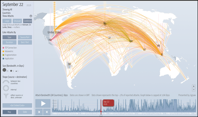
Figure 1: A view of the Mirai DDoS attack on the Krebs on Security website, courtesy of DigitalAttackMap.com, a collaboration between NETSCOUT Arbor and Google Jigsaw
Stuxnet
Stuxnet was the first known documented cyber weapon released to permanently damage Iran's assets. In this case, it was a worm that was released to damage SCADA-based Siemens programmable logic controllers (PLCs) and used a rootkit to modify the rotational speed of motors under the direct control of the PLC. The designers went out of their way to ensure the virus targeted only devices with rotational spin rates of slave variable frequency drives attached to Siemens S7-300 PLCs rotating at 807 Hz and 1210 Hz, as they are typically used for pumps and gas centrifuges for uranium enrichment.
The attack presumably started in April or March of 2010. The infection process followed these steps:
- Initial infection: The worm started by infecting a host Windows machine exploiting vulnerabilities found in previous virus attacks. It is thought to have spread by the insertion of a USB drive in the initial machine. It used four zero-day exploits simultaneously (an unprecedented level of sophistication). The exploits used a rootkit attack using user-mode and kernel-mode code and installed a stolen yet properly signed and certified device driver from Realtek. This kernel-mode signed driver was necessary to hide Stuxnet from wary antivirus packages.
- Windows attack and spread: Once installed through the rootkit, the worm began to search the Windows system for files typical of a Siemens SCADA controller, WinCC/PCS 7 SCADA, also known as Step-7. If the worm happened to find Siemens SCADA control software, it attempted to access the Internet through a C2 using malformed URLs (www.mypremierfutbol.com and www.todaysfutbol.com) to download more recent versions of its payload. It then dug further into the filesystem to search for a file called
s7otbdx.dll, which served as a critical communications library between the Windows machine and the PLC. Step-7 included a hardcoded password database which was exploited through another zero-day attack. Stuxnet inserted itself between the WinCC system and thes7otbdx.dllto act as a man-in-the-middle attacker. The virus started its operation by recording the normal operation of the centrifuges.
- Destruction: When it decided to coordinate the attack, it replayed the prerecorded data to the SCADA systems, which had no reason to believe anything was compromised or behaving erratically. Stuxnet delivered its damage by manipulating the PLCs with two different coordinated attacks to damage the entire array of Iran's facility. The damage to the rotors of the centrifuge occurred slowly over time, running in 15- or 50-minute increments separated by 27 days of normal operation. This resulted in improperly enriched uranium as well as cracked and destroyed rotor tubes in the centrifuges.
It is believed that over 1,000 uranium enrichment centrifuges were crippled and damaged by this attack on Iran's main enrichment facility in Natanz, Iran. Today the Stuxnet code is available online and is essentially an open source playing field to create derivative exploits (https://github.com/micrictor/stuxnet).
Chain Reaction
Chain Reaction is an academic study that shows a new breed of cyber attacks focused on PAN mesh networks that can be executed without any link to the Internet. Additionally, it shows how vulnerable remote IoT sensor and control systems can be. The attack vector was Philips Hue light bulbs typically found in consumer homes that can be controlled by the Internet and smartphone apps. The exploit can be scaled up to smart city attacks and initiated by simply inserting a single infected smart light.
Philips Hue lights use the Zigbee protocol to establish a mesh. Zigbee lighting systems fall under a program called the Zigbee Light Link (ZLL) to force a standard method for lighting interoperability. ZLL messages are not encrypted or signed, but encryption is used to secure keys exchanged if a light is added to the mesh. This master key is known to everyone in the ZLL alliance and was subsequently leaked. ZLL also forces light bulbs joining the mesh to be in very close proximity to the initiator. This prevents one from taking over their neighbor's lights. Zigbee also offers an over-the-air (OTA) reprogramming method; however, the firmware bundles are encrypted and signed.
The researchers used a four-phase attack plan:
- The attack would break the encryption and signing of the OTA firmware bundle.
- It would write and deploy a malevolent firmware upgrade to a single light bulb using the broken encryption and signing keys.
- The compromised bulb would join the network based on the stolen master key and exploit the proximity security through a found zero-day defect in the popularly used Atmel AtMega part.
- After successfully joining a Zigbee mesh, it would then send its payload to neighboring lights and infect them rapidly. This would expand based on percolation theory and infect entire city populations of lighting systems.
Zigbee uses AES-CCM (part of the IEEE 802.15.4 standard and covered later in this chapter) encryption to encrypt OTA firmware updates. To break the firmware encryption, the attackers used correlation power analysis (CPA) and differential power analysis (DPA).
This is a sophisticated form of attack where a device such as the light bulb controller hardware is placed on a bench and the power that it consumes is measured. Given sophisticated control, one can measure the dynamic power used by a CPU executing an instruction or moving data (for example, when an encryption algorithm is executed). This is called simple power analysis (SPA), in which it is still be very difficult to crack the key. CPA and DPA extend capabilities beyond SPA by using a statistical correlation.
Rather than attempt to determine one bit at a time in cracking a key, CPA can resolve byte-wide quantities. Power traces are captured by an oscilloscope and split into two sets. The first set assumes an intermediate value being cracked is set to 1 and the other set assumes it is set to 0. By subtracting the mean of these sets, the true value of an intermediate value is exposed.
Using both DPA and CPA, the researchers broke the Philips Hue lighting system as follows:
- The researchers used the CPA to crack the AES-CBC. The attackers had no key, no nonce, no initialization vector. This resolved the key, which was used in the same manner to attack the nonce.
- They used DPA to crack the AES-CTR counter mode to break the firmware bundling encryption. Researchers found 10 locations that the AES-CTR seemed to execute, which created 10x the possibilities.
- They then focused on breaking the Zigbee proximity protection for joining a network. The zero-day exploit was the result found by inspecting Atmel's source code for the bootloader on the SOC. Upon reviewing the code, they found that the proximity check was valid when starting a scan request in Zigbee. If they started with any other message, the proximity check was bypassed. This allowed them to join any network.
A true attack could force an infected bulb to infect others within a few hundred meters with a payload to remove the firmware update ability of each bulb so they can never be recovered. The bulbs would effectively be under malicious control and would have to be destroyed. The researchers were able to build a fully automated attack system and attached it to a drone that systematically flew within range of Philips Hue lights in a campus environment and hijacked each one.
More information on the CPA attack on Zigbee can be found here: E. Ronen, A. Shamir, A. O. Weingarten and C. O'Flynn, IoT Goes Nuclear: Creating a ZigBee Chain Reaction, 2017 IEEE Symposium on Security and Privacy (SP), San Jose, CA, 2017, pp. 195-212. An excellent tutorial and the source code to generate a CPA attack can be found on the ChipWhisperer Wiki: https://wiki.newae.com/AES-CCM_Attack.
Physical and hardware security
Many IoT deployments will be in remote and isolated areas leaving sensors and edge routers vulnerable to physical attack. Additionally, the hardware itself needs modern protection mechanisms common in processors and the circuitry of mobile devices and personal electronics.
RoT
The first layer of hardware security is the establishment of a RoT. The RoT is a hardware-validated boot process that ensures the first executable opcode starts from an immutable source. This is the anchor of the boot process that subsequently plays a role in bootstrapping the rest of the system from BIOS to the OS to the application. An RoT is a baseline defense against a rootkit.
Each phase validates the next phase in the boot process and builds a Chain of Trust. An RoT can have different starting methods such as:
- Boot from ROM or nonwritable memory to store the image and root key
- One-time programmable memory using fuse bits for root key storage
- Boot from a protected memory region that loads code into a protected memory store
An RoT also needs to validate each new phase of boot. Each phase of boot maintains a set of cryptographically signed keys that are used to verify the next phase of boot:

Figure 2: Establishing a RoT. Here is a five-phase boot building up a Chain of Trust and starting with a boot loader in immutable read-only memory. Each phase maintains a public key that is used to verify the authenticity of the next component loaded.
Processors that support an RoT are architecturally unique. Intel and ARM support the following:
- ARM TrustZone: ARM sells a security silicon IP block for SOC manufacturers that provides a hardware RoT as well as other security services. TrustZone divides hardware into secure and non-secure "worlds." TrustZone is a separated microprocessor from the non-secure core. It runs a Trusted OS specially designed for security that has a well-defined interface to the non-secure world. Protected assets and functions reside in the trusted core and should be lightweight by design. The switching between worlds is done through hardware context switching, eliminating the need for secure monitor software. Other uses for TrustZone are to manage system keys, credit card transactions, and digital rights management. TrustZone is available for A "application" and M "microcontroller" CPUs. This form of secure CPU, Trusted OS, and RoT is called a trusted execution environment (TEE).
- Intel Boot Guard: This is a hardware-based mechanism that provides a verified boot that cryptographically verifies the initial boot block or uses a measuring process for validation. Boot Guard requires a manufacturer to generate a 2048-bit key for verifying the initial block. The key is split into a private and public portion. The public key is imprinted by programmatically "blowing" fuse-bits during manufacturing. These are immutable one-time fuses. The private portion generates the signature of the subsequently verified portion of the boot phase.
Key management and trusted platform modules
Public and private keys are critical to ensuring a secure system. The keys themselves need proper management to ensure their safety. There are hardware standards for key security and one particularly popular mechanism is the Trusted Platform Module (TPM). The specification for TPM was written by the Trusted Computing Group and is an ISO and IEC standard. The current specification is TPM 2.0 released in September of 2016. Computer assets sold to the DoD require TPM 1.2.
A TPM is a discrete hardware component with a secret RSA key burned into the device at manufacturing.
Generally, a TPM is used to hold, secure, and manage other keys for services such as disk encryption, RoT booting, verifying the authenticity of hardware (as well as software), and password management.
A TPM can create a hash of a litany of software and hardware in a "known good" configuration that can be used to verify tampering at runtime. Additional services include assisting in SHA-1 and SHA-256 hashing, AES encryption blocks, asymmetric encryption, and random number generation. Several vendors produce TPM devices such as Broadcom, Nation Semiconductor, and Texas Instruments.
Processor and memory space
We have already discussed various exploits and processor technologies that act as countermeasures. Two predominant technologies to look for in CPU and OS facilities include non-execution memory and address space layout randomization. Both types of technologies are meant to burden or prevent buffer-overflow and stack-overrun types of malware injection:
- Non-execution protection (or executable space protection): This is a facility enabled by the hardware used by the OS to mark areas of memory as non-executable. The intent is to map only areas where verified and legitimate code resides to be the only regions of addressable memory that can execute an operation. If an attempt is made to implant malware through a stack-overflow type of attack, the stack will be marked as non-executing and an attempt to force the instruction pointer to execute there would result in a machine exception.
Non-executable memory uses an NX bit as a means to map the region as non-executable (through the translation lookaside buffer). Intel uses the Execute Disable (XD) Bit, and ARM uses an Execute Never (XN) Bit. Most operating systems, such as Linux, Windows, and several RTOSes, support such features.
- Address space layout randomization (ASLR): While more of an OS treatment of virtual memory space than a hardware feature, it is important to consider ASLR. This type of countermeasure targets buffer-overflow as well as return-to-libc attacks. These attacks are based on an attacker understanding the layout of memory and forcing calls to certain benign code and libraries. Calling these libraries becomes particularly laborious if the memory space is randomized on each boot. Linux provides the ASLR ability using the PAX and Exec Shield patches. Microsoft provides protection for heap, stack, and process blocks as well.
Storage security
Often, IoT devices will have persistent storage at the edge node or on a router/gateway. Intelligent fog nodes will require persistent storage of some kind as well.
The security of data on the device is imperative to prevent malicious malware from being deployed and to protect the data in the event the IoT device is stolen. Most mass storage devices, such as flash modules and rotating disks, have models with encryption and security technology.
The FIPS 140-2 (Federal Information Processing Standard) is a government regulation detailing encryption and security requirements for IT devices that manage or store sensitive data. It not only specifies technical requirements but also defines policies and procedures. FIPS 140-2 has several levels of compliance:
- Level 1: Software-only encryption. Limited security.
- Level 2: Role-based authentication is necessary. Requires the ability to detect physical tampering using tamper-evident seals.
- Level 3: Includes physical tamper resistance. If the device is tampered with, it will erase critical security parameters. Includes cryptographic protection and key management. Includes identity-based authentication.
- Level 4: Advanced tamper protection for products designed to work in physically unprotected environments.
In addition to encryption, it is also necessary to consider the security of media when it's decommissioned or disposed of. It is fairly easy to retrieve contents from old storage systems. There are additional standards on how to wipe and erase content securely from media (whether it's a magnetically based disk or a phase-change flash component). NIST also publishes documents on securely erasing and wiping content such as the NIST Special Publication 800-88 for Secure Erase.
Physical security
Tamper resistance and physical security are particularly important for IoT devices. In many scenarios, an IoT device will be remote and without the safeguards of on-premises devices. This is analogous to the Enigma machine of World War Two. Retrieving a working machine from the German submarine U-110 helped break the cipher. An attacker with access to the IoT device can use whatever tools are at their leisure to crack the system, as we saw with the Chain Reaction exploit.
Side-channel attacks, as shown, deal with power analysis; other forms are timing attacks, cache attacks, electromagnetic field emissions, and scan-chain attacks. The common theme of a side-channel attack is the compromised unit is essentially a device under test (DUT). This means the device will be observed and measured in a controlled environment.
Additionally, techniques like differential power analysis (DPA) use statistical analysis approaches to look for the correlations of random input to output. The statistical analysis only works if the system behaves identically from run to run with the same input:
| Methodology | |
|
Timing attacks |
Attempts to exploit small differences in the timing of algorithms. For example, measuring the timing of a password decoding algorithm and observing early exits from the routine. Attackers also can observe cache utilization to witness the characteristics of the algorithm. |
|
Simple power analysis (SPA) |
Similar to a timing attack but measures large changes in dynamic power or current due to the behavior of an algorithm and opcodes. Public keys are particularly susceptible. The analysis needs few traces to work, but the traces need a high degree of precision. As most cryptographic algorithms are mathematically intensive, different opcodes will show up as different power signatures in a trace. |
|
Differential power analysis (DPA) |
Measures dynamic power but can observe changes that are too small to be observed directly as in SPA. By injecting random input (such as different random keys) into a system, the attacker can perform thousands of traces to build a data-dependent set. Attacking an AES algorithm, for example, simply means building two sets of traces depending on the value of the bit (0 or 1) being cracked. The sets are averaged, and the difference between the 0 and 1 set is plotted to show the effect of the random input to the output. |
Methods of prevention are well known, and several can be licensed and used in a variety of hardware. Countermeasures for these types of attacks include:
- Modify the encryption function to minimize the use of the key. Use a short-lived session key based on a hash of the actual key.
- For timing attacks, randomly insert functions that will not perturb the original algorithm. Use different random opcodes to create a large work function for the attacks.
- Remove conditional branches that depend on the key.
- For power attacks, decrease leakage at every opportunity and limit the number of operations per key. This reduces the attacker working set.
- Induce noise into power lines. Use variable timing operations or skew clocks. Change the order of independent operations. This reduces correlation factors around the S-Box calculation.
Other hardware considerations include:
- Prevent access to debug ports and channels. Often these are exposed on the PCA as serial ports and JTAG ports. Headers should be removed and fuse bits blown to prevent debug access in the most hardened cases.
- ASICs typically use ball grid array (BGA) pads to attach to a PCA. High- performance adhesives and thermally resistant glue should be used to surround the package and may cause irreparable damage if tampered with.
Shell security
We have examined hardware security up to this point, but the architect must also consider network and shell security of the system. Network security is covered in Chapter 9, Edge Routing and Networking. We will explore one area of shell connectivity in this section: SSH, or secure shell.
SSH is a cryptographic network protocol used to provide services like login, command-line control, remote access, and root access to modern operating systems. SSH uses a secure channel over an unsecure network, employing methods such as SHA-2 and SHA25. Additionally, authentication is performed using various methods, such as public key exchange or simple passwords. Typically, SSH sessions use port 22.
Although the protocol uses authentication and encryption methods, there are still vulnerabilities:
- A preferred method is to use public key exchange when authenticating. These are far better than password-based security.
- A typical attack vector is brute force username/password attempts. SSH ports provide an easy opportunity for attacks as devices may keep the port open and exposed on the Internet. There should never be empty passwords on any system. Additionally, use very strong usernames and passwords, using psuedorandom password generators.
- SSH sessions should never sit idle. It is possible for an SSH session to terminate if there is no activity by modifying the
ClientAliveInterval. - Use another port beside port 22. Many people simply chose port 222 or 2222 for convenience. It is recommended to use an unused port far from these easily guessed integers.
- Use two-factor authentication methods.
Cryptography
Encryption and secrecy are absolute requirements of IoT deployments. They are used for securing communication, protecting firmware, and authentication. Regarding encryption, there are generally three forms to consider:
- Symmetric key encryption: Encryption and decryption keys are identical. RC5, DES, 3DES, and AES are all forms of symmetric key encryption.
- Public key encryption: The encryption key is published publicly for anyone to use and encrypt data. Only the receiving party has a private key used to decrypt the message. This is also known as asymmetric encryption. Asymmetric cryptography manages data secrecy, authenticates participants, and forces non-repudiation. Well-known Internet encryption and message protocols such as elliptic curve , PGP, RSA, TLS, and S/MIME are considered public keys.
- Cryptographic hash: This maps data of an arbitrary size to a bit string (called the digest). This hash function is designed to be "one way." Essentially, the only way to recreate the output hash is to force every possible input combination (it cannot be run in reverse). MD5, SHA1, SHA2, and SHA3 are all forms of one-way hashes. These are typically used to encode digital signatures such as signed firmware images, message authentication codes (MAC), or authentication. When encrypting a short message like a password, the input may be too small to effectively create a fair hash; in that case, a salt or non-private string is appended to the password to increase the entropy. A salt is a form of key derivation function (KDF):

Figure 3: Elements of cryptography. Here are symmetric, asymmetric, and hashing functions. Note the key usage in symmetric and asymmetric cryptography. Symmetric hashing has the requirement of using identical keys to encrypt and decrypt data. While faster than asymmetric encryption, the keys need to be secured.
Symmetric cryptography
In encryption, plaintext refers to the unencrypted input and the output is called ciphertext, as it is encrypted. The standard for encryption is the Advanced Encryption Standard (AES), which replaced older DES algorithms dating from the 1970s. AES is part of the FIPS specification and the ISO/IEC 18033-3 standard used worldwide. AES algorithms use fixed blocks of 128, 192, or 256 bits. Messages larger than the bit width will be split into multiple blocks. AES has four basic phases of operation during the cipher. The pseudocode for a generic AES encryption is shown here:
// Psuedo code for an AES-128 Cipher
// in: 128 bits (plaintext)
// out: 128 bits (ciphertext)
// w: 44 words, 32 bits each (expanded key) state = in

w=KeyExpansion(key) //Key Expansion phase (effectively encrypts key itself)
AddRoundKey(state, w[0, Nb-1]) //Initial Round

for round = 1 step 1 to Nr–1 //128 bit= 10 rounds, 192 bit = 12 rounds, 256 bit = 14 rounds
  SubBytes(state) //Provide non-linearity in the cipher
  ShiftRows(state) //Avoids columns being encrypted independently
  MixColumns(state) //Transforms each column and adds diffusion to the cipher
  AddRoundKey(state, w[round*Nb, (round+1)*Nb-1]) //Generates a subkey
end for

SubBytes(state) //Final round and cleanup.
ShiftRows(state)
AddRoundKey(state, w[Nr*Nb, (Nr+1)*Nb-1]) out = state
AES key lengths can be 128, 192, or 256 bits. Generally, the larger the key length the better the protection. The size of the key is proportional to the number of CPU cycles needed to encrypt or decrypt a block: 128-bit needs 10 cycles, 192-bit needs 12 cycles, and 256-bit needs 14 cycles.
Since AES is a block cipher, the data needs to be padded to the multiple of the key length. The architect of an IoT or edge solution should consider this if the data in transit is length sensitive.
Block ciphers represent encryption algorithms that are based on a symmetric key and operate on a single block of data. Modern ciphers are based on Claude Shannon's work on product ciphers in 1949. A cipher mode of operation is an algorithm that uses a block cipher and describes how to repeatedly apply a cipher to transform large amounts of data consisting of many blocks. Most modern ciphers also require an initialization vector (IV) to ensure distinct ciphertexts even if the same plaintext is entered repeatedly. There are several modes of operation, such as:
- Electronic Codebook (ECB): The most basic form of AES encryption, but used with other modes to build more advanced security. Data is divided into blocks, and each is encrypted individually. Identical blocks will produce identical ciphers, which makes this mode relatively weak.
- Cipher block chaining (CBC): Plaintext messages XOR'd with the previous ciphertext before being encrypted.
- Cipher feedback (CFB) chaining: Similar to CBC but forms a stream of ciphers (the output of the previous cipher feeds into the next). CFB chaining depends on the previous block cipher to provide input to the current cipher being generated. Because of the dependency of previous ciphers, CFB chaining cannot be processed in parallel. Streaming ciphers allows for a block to be lost in transit, but subsequent blocks can recover from the damage.
- Output Feedback (OFB) Chaining: Similar to CFB, a streaming cipher but allows error correcting codes to be applied before encryption.
- Counter (CTR): Turns a block cipher into a stream cipher but uses a counter. The incrementing counter feeds each block cipher in parallel, allowing fast execution. The nonce and counter are concatenated together to feed the block cipher.
- CBC with Message Authentication Code (CBC-MAC): A MAC (also known as tag or MIC) is used to authenticate a message and confirm the message came from the stated sender. The MAC or MIC is then added to the message for verification by the receiver.
These modes were first constructed in the late 1970s and early 1980s and were advocated by the National Institute of Standards and Technology (NIST) in FIPS 81 as DES modes. These modes provide encryption for the confidentiality of information but will not protect against modification or tampering. To do that, a digital signature is needed and the security community developed CBC-MAC for authentication. Combining CBC-MAC with one of the legacy modes was difficult until algorithms like AES-CCM were established, which provide both authentication and secrecy. CCM stands for Counter with CBC-MAC Mode.
CCM is an important encryption mode used to sign and encrypt data and is used in a plethora of protocols covered in this book including Zigbee, Bluetooth Low Energy, TLS 1.2 (after key exchange), IPSEC, and 802.11 Wi-Fi WPA2.
AES-CCM makes use of dual ciphers: CBC and CTR. AES-CTR, or AES Counter Mode, is used for the general decryption of the ciphertext stream flowing in. The incoming stream contains an encrypted authentication tag. AES-CTR will decrypt the tag as well as the payload data. An "expected tag" is formed from this phase of the algorithm. The AES-CBC phase of the algorithm tags as input the decrypted blocks from the AES-CTR output and the original header of the frame. The data is encrypted; however, the only relevant data needed for authentication is the calculated tag. If the AES-CBC calculated tag differs from the AES-CTR expected tag, then there is the possibility that the data was tampered with in transit.
The following figure illustrates an incoming encrypted stream of data that is both authenticated using AES-CBC and decrypted using AES-CTR. This ensures both the secrecy and authenticity of the origin of a message:

Figure 4: The AES-CCM mode
One consideration for IoT deployments in a fully connected mesh is the number of keys necessary. For n nodes in a mesh that desire bidirectional communication, there are n(n-1)/2 keys or O(n2).
Asymmetric cryptography
As indicated earlier, asymmetric cryptography is also called public key cryptography. Asymmetric keys are generated in pairs (encrypting and decrypting). The keys can be interchangeable, meaning a key could both encrypt and decrypt, but that is not a requirement. The typical use, however, is to generate a pair of keys and keep one private and the other public. This section describes the three foundational public key cryptograms: RSA, Diffie-Hellman, and Elliptical Curves.
Note that unlike symmetric key counts in a mesh where any node can communicate with any other node, asymmetric cryptography only requires 2n keys or O(n).
The first asymmetric public key encryption method described is the Rivest-Shamir-Adleman algorithm, or RSA, developed in 1978. It is based on a user finding and publishing the product of two large prime numbers and an auxiliary value (public key). The public key can be used by anyone to encrypt a message, but the prime factors are private. The algorithm operates as follows:
- Find two large primes, p and q.
n = pq

- Public key exponent: Choose an integer e so that
 , e is coprime to
  ; a typical value is 216 + 1 = 65537.
- Private key exponent: Compute d to solve the congruence relation
 .
.
Therefore, to encrypt a message using the public key (n,e) and to decrypt a message using the private key (n,d):
- Encrypt: Ciphertext = (plaintext)e mod n
- Decrypt: Plaintext = (ciphertext)d mod n
It is often the case that artificial padding is injected into a message before encryption to avoid cases of short messages failing to produce good ciphertext.
Perhaps the best-known form of asymmetric key exchange is the Diffie-Hellman key exchange process (named after Whitfield Diffie and Martin Hellman). Typical of asymmetric cryptography is the notion of a trapdoor function, which takes a given value A and produces an output B. However, trapdoor function B does not produce A.
The Diffie-Hellman method of key exchange allows two parties (Alice A and Bob B) to exchange keys without any previous knowledge of any shared secret key s. The algorithm is based on the plaintext exchange of a starting prime number, p, and a prime generator. The generator g is a primitive root modulo p. Let Alice's private key be a and Bob's private key be b. Then, A=ga mod p and B=gb mod p. Alice computes the secret key as s=Ba mod p, and Bob computes the secret key as s=Ba mod p.
In general, (ga mod p)b mod p = (gb mod p)a mod p:

Figure 5: Diffie-Hellman key exchange. The process begins with the plaintext exchange of an agreed upon prime and generator of prime. With an independent private key generated by Alice and Bob, the public keys are generated and sent in plaintext over the network. This is used to generate a secret key used for encryption and decryption.
The strength of this form of secure key exchange is generating a true random number for each private key. Even the slight predictability of a pseudo-random number generator (PRNG) can lead to breaking the encryption. However, the principal issue is the lack of authentication, which can lead to an MITM attack.
The other form of key exchange is Elliptic-Curve Diffie-Hellman (ECDH) and was proposed by Koblitz and Miller in 1985. It is based on the algebra of elliptic curves over a finite field. NIST has endorsed ECDH, and the NSA allows ECDH for top-secret material using 384-bit keys. Elliptic curve cryptography (ECC) shares these basic tenets regarding the properties of an elliptical curve:
- The curve is symmetrical about the x-axis. If (x,y) represents a point on the curve, then (x,-y) will also be on the curve. See the next figure, which illustrates this fact.
- A straight line will intersect the elliptic curve at no more than three points.
The process of ECC starts with drawing a straight line from a given point on the edge towards MAX. A line is drawn from point A to B. A dot function is used to draw a line between two points and then draw a line straight up (or down) from the new unlabeled intersection to its counterpart on the positive or negative y axis. This process is repeated n times, where n is the key size.
This process is analogous to seeing the end results of a pool table after a ball has been hit and strikes the cushions many times. An observer seeing the ending location of the ball would have a difficult time determining where the original location of the ball was.
MAX corresponds maximum value on the x axis, placing a limit on how far a vertex will stretch. If by chance the vertex is greater than MAX, the algorithm forces the value that would have extended beyond the MAX limit and sets a new point x-MAX distance away from the origin A. MAX is equivalent to the key size being used. A large key size results in more vertices being constructed and increasing strength of secrecy. Essentially this is a wraparound function:

Figure 6: Elliptical curve cryptography (ECC). Here is a standard elliptical curve on an x, y axis. The process starts by following straight line paths from a given point A to a second point and locating the third new unlabeled intersection. A line is drawn to the opposite but identical y plane coordinate, which now becomes a labeled entity. The process continues for n points, which correspond to the key length.
Elliptical curves are becoming prevalent over RSA. Modern browsers are capable of supporting ECDH, which is the preferred method of authentication over SLL/TLS. ECDH is also found in Bitcoin, as we will see later, and several other protocols. RSA is only used now if an SSL certificate has a matching RSA key.
The other advantage is that the key lengths can be kept short and still have the same cryptographic strength as a legacy method. For example, a 256-bit key in ECC is equivalent to a 3072-bit key in RSA. The importance of this should be considered for constrained IoT devices.
Cryptographic hash (authentication and signing)
Hashing functions represent the third type of cipher technology to consider. These are typically used to generate a digital signature. They are also considered "one-way" or impossible to invert. To recreate the original data after passing through a hash function would be a brute-force attack of every possible combination of inputs. The key attributes of a hashing function include:
- The function always generates the same hash from the same input.
- It is quick to compute but not free (see proof of work).
- It is non-reversible and cannot regenerate the original message from the hash value.
- A small change to the input will result in significant entropy or a change in the output.
Two different messages will never have the same hash value.
The effects of cryptographic hashing functions like SHA1 (Secure Hash Algorithm) can be demonstrated by altering just one character in a longer string:
Input:
Boise IdahoSHA1 Hash Output:
375941d3fb91836fb7c76e811d527d6c0a251ed4Input:
Milwaukee WisconsinSHA1 Hash Output:
9e318d4243262e59e2515b47a5c99771071acd8d
SHA algorithms are used extensively in applications such as:
- Git repositories
- TLS certificate signing for web browsing (HTTPS)
- Validating file or disk image content authenticity
Most hash functions are built upon the Merkle-Damgård construction. Here, the input is split into equally sized blocks that are processed serially with a compression function combined with the output of the previous compression. An initialization vector (IV) is used to seed the process. By using a compression function, the hash is resistant to collisions. SHA-1 is built upon this Merkle-Damgård construction:

Figure 7: SHA-1 algorithm. Input split into five 32-bit chunks
In general, the SHA algorithm's input message must be less than 264 bits. The message is processed in 512-bit blocks sequentially. SHA-1 is now superseded with strong kernels such as SHA-256 and SHA-3. SHA-1 was found to have "collision" within the hash. While it would take approximately 251 to 257 operations to find a collision, it would take only a few thousand dollars of rented GPU time to resolve the hash. Thus, the recommendation is to move to the strong SHA models.
MD5 is no longer considered safe and is no longer approved for used in cryptography. Rather stronger methods such as SHA-3 are recommended.
Public key infrastructure
Asymmetric cryptography (public key) is a mainstay of Internet commerce and communication. It has routinely been used for SSL and TLS connection on the web. A typical use is public key encryption, where data in transit is encrypted by anyone holding the public key but can only be decrypted by the holder of the private key. Another use is digital signatures, where a blob of data is signed with a sender's private key and the receiving party can verify the authenticity if they hold the public key.
To assist with providing public keys with confidence, a process known as public key infrastructure (PKI) is used. To guarantee authenticity, trusted third parties known as certificate authorities (CAs) manage roles and policies to create and distribute digital certificates. Symantec, Comodo, Let's Encrypt, and GoDaddy are the largest public issuers of TLS certificates. X.509 is a standard that defines public key certificate formats. It is the basis of TLS/SSL and HTTPS secure communication. X.509 defines such things as the encryption algorithm used, expiration dates, and the issuer of the certificate.
PKI consists of a registration authority (RA) that verifies the sender and manages specific roles and policies and can revoke certificates. The RA also communicates with a validation authority (VA) to transfer revocation lists. The CA issues the certificate to the sender. When a message is received, the key can be validated by the VA to verify that it hasn't been revoked.
The following figure shows an example of PKI infrastructure. It includes the CA, RA, and VA systems used and the phases of granting and verifying a key granted for encrypting a message:

Figure 8: PKI infrastructure example
Network stack – Transport Layer Security
Transport Layer Security (TLS) has been covered in many areas of this book, from TLS and DTLS for MQTT and CoAP to network security over the WAN and PAN security. Each has had some form of reliance on TLS. It also brings together all the cryptographic protocols and technologies we have mentioned. This section briefly covers the TLS1.2 technology and process.
Originally, SSL (Secure Sockets Layer) was introduced in the 1990s but was replaced by TLS in 1999. TLS 1.2 is the current specification in RFC5246 as of 2008. TLS 1.2 includes an SHA-256 hash generator to replace SHA-1 and strengthen its security profile.
In TLS encryption, the process is as follows:
- The client opens a connection to a TLS-capable server (port 443 for HTTPS).
- The client presents a list of supported ciphers that can be used.
- The server picks a cipher and hash function and notifies the client.
- The server sends a digital certificate to the client that includes a CA and the server's public key.
- The client confirms the validity of the secret.
- A session key is generated either by:
- Encrypting a random number with the server's public key and sending the result to the server. The server and client then use the random number to create a session key that is used for the duration of the communication.
- Using a Dixie-Hellman key exchange to generate a session key used for encryption and decryption. The session key is used until the connection is closed.
- Communication starts using the encrypted channel.
Shown below is the handshaking process for TLS1.2 communication between two devices:

Figure 9: TLS 1.2 handshake sequence
Datagram Transport Layer Security (DTLS) is a communications protocol at the datagram layer based on TLS. (DTLS 1.2 is based on TLS 1.2.) It is intended to produce similar security guarantees. The CoAP lightweight protocol uses DTLS for security.
Software-Defined Perimeter
Earlier in the book, Chapter 9, Edge Routing and Networking, the concepts of software-defined networks and overlay networks were discussed. Overlay networks and their ability to create microsegments is extremely powerful especially in mass IoT scaling and situations where a DDoS attack can be mitigated. An additional component of software-defined networking is called Software-Defined Perimeter (SDP) and is worth a discussion in terms of the overall security picture.
SDP architecture
An SDP is an approach to network and communication security where no trust model exists. It is based on the Defense Information Systems Agency (DISA)'s black cloud. Black cloud means information is shared on a need-to-know basis. An SDP can mitigate attacks such as DDoS, MITM, zero-day exploits, and server scanning, among others. Along with providing an overlay and micro-segmentation for each attached device, the perimeter creates an invitation-only (identity-based) security perimeter around users, clients, and IoT devices.
An SDP can be used to create an overlay network, which is a network built on top of another network. A historical reference is legacy Internet services built upon the preexisting telephone network. In this hybrid networking approach, the distributed control plane remains the same. Edge routers and virtual switches steer data based on control plane rules. Multiple overlay networks can be built on the same infrastructure. Since an software-defined networking (SDN) remains persistent in much the same way as a wired network, it is ideal for real-time applications, remote monitoring, and complex event processing. The ability to create multiple overlay networks using the same edge components allows micro-segmentation, where different resources have a direct relationship with different consumers of data. Each resource-consumer pair is a separate immutable network that is only able to see outside of its virtual overlay as the administrator chooses.
The ability to create multiple overlay networks using the same edge components allows for micro-segmentation where each endpoint in a globally distributed IoT network can build individual and isolated network segments over the existing network infrastructure. In theory, every sensor could be isolated from another. This is a powerful tool for enabling enterprise connectivity for IoT deployments as services and devices can be isolated and protected from each other.
The following graphic depicts an SDN overlay example. Here, a corporation has three remote franchises with a number of different IoT and edge devices at each store. The network resides on an SDN overlay network with micro-segments isolating POS and VOIP systems that are corporately managed from various sensors for security, insurance, and cold storage monitoring. Third-party service providers can manage various remote sensors using an isolated and secure virtual overlay network only for the device they manage:

Figure 10: An example SDN overlay network
An SDP can further extend security by developing an invitation system, forcing a pair of devices to authenticate first and connect second. Only a preauthorized user or client can be added to a network. That authorization is extended by an invitation from the control plane via email or some registration facility. If the user accepts the invitation, client certificates and credentials are extended to that system alone. The resource extending the invitation maintains a record of extended certificates and will provide an overlay connection only when both parties accept the role.
The real-world analogy is how one sends invitations for a party. Invitations are mailed out to selected individuals with a date, time, address, and other details. Those individuals may or may not want to attend the party (it is up to them). The alternative is to advertise on the web, TV, and radio that you are having a party and then authenticate each person as they arrive at the door.
Blockchains and cryptocurrencies in IoT
Blockchains exist to solve a trust model (not necessarily a security issue). Blockchains are public, digital, and decentralized ledgers or cryptocurrency transactions. The original cryptocurrency blockchain was Bitcoin, but there are over 2000 new currencies on the market, such as Ethereum, Ripple, and Dash. The power of a blockchain is that there is no single entity controlling the state of transactions. It also forces redundancy in the system by ensuring everyone using a blockchain also maintains a copy of the ledger.
Assuming there is no inherent trust in blockchain participants, the system must live in consensus.
A good question to ask is if we have solved identity management and security with asymmetric cryptography and key exchanges, why are blockchains needed to exchange data or currency? This is not enough for the exchange of money or data of value. One thing to note is that since the inception of information theory, when two devices communicate, Bob and Alice, they send a message or a bit of data. That information is still retained by Bob even if Alice receives a copy. When exchanging money or contracts, that data must leave one source and arrive at another.
There is only a single instance. Authenticity and encryption are tools needed for communication, but a new method to transfer ownership had to be invented:

Figure 11: Ledger topologies. A centralized ledger is the typical process of a single controlling agent maintaining "the books." Cryptocurrencies use either decentralized or distributed ledgers.
Blockchain secure cryptocurrencies are particularly relevant to IoT. Some example use cases include:
- Machine to machine payments: The IoT needs to ready itself for machine exchanging services for currency.
- Supply chain management: In this case, the movement and logistics in managing inventory, moving goods, and logistics can replace paper-based tracking with blockchain immutability and security. Every container, movement, location, and state can be tracked, verified, and certified. Attempts to forge, delete, or modify tracking information becomes impossible.
- Solar energy: Imagine residential solar as a service. In this case, solar panels installed on a customer home are generating energy for the home. Alternatively, they can also send energy back to the grid to power someone else (perhaps in exchange for carbon credits).
Bitcoin (blockchain-based)
The cryptocurrency portion of Bitcoin is different from the blockchain itself. Bitcoin is an artificial currency. It has no commodity or value backing like gold or a government (in the case of a fiat currency). It is also not physical; it only exists in a network construct. Finally, the supply or number of Bitcoins is not determined by a central bank or any authority. It is completely decentralized. Like other blockchains, it is built up from public key cryptography, a large and distributed peer-to-peer network, and a protocol that defines the Bitcoin structure. While not the first to conceive of digital cash, Satoshi Nakamoto (alias) posted a paper in 2008 called Bitcoin: A Peer-to-Peer Electronic Cash System to a cryptography list. In 2009, the first Bitcoin network was online, and Satoshi mined the first block (the genesis block).
The concept of a blockchain means that there is a block representing the current portion of a blockchain. A computer connected to the blockchain network is called a node. Each node participates in validating and relaying transactions by obtaining a copy of the blockchain and is essentially an administrator.
A distributed network based on peer-to-peer topologies exists for Bitcoin. Metcalfe's Law applies here since the value of a cryptocurrency like Bitcoin is based on the size of the network. The network maintains the system of records (the ledger). The problem is, where do you find a source of computing willing to share their compute time for monitoring ledgers? The answer is to build a reward system called Bitcoin mining.
The transaction process is shown in the following figure. It starts with a transaction request. The request is broadcast to a peer-to-peer (P2P) network of computers called nodes. The peer network is responsible for validating the authenticity of the user. Upon validation, the transaction is verified and combined with other transactions to create a new block of data for the distributed ledger. When a block is full, it is added to the existing blockchain, making it immutable.
The Bitcoin authentication, mining, and validation process is shown in the following illustration:

Figure 12: Bitcoin blockchain transaction process
Shown in the graphic is the exchange of 0.000554 Bitcoins between Alice and Bob with a service fee of 0.0001 BTC. Alice initiates the transaction by signing the contents of the transaction with the previous transaction hash against Alice's private key. Alice also includes her public key in the inputScriptSig script. The transaction is then broadcast to the Bitcoin P2P network for inclusion in a block and validation. The network competes to validate and discover a working nonce based on the current strength of complexity. If a block is discovered, the server broadcasts the block to peers for validation and then inclusion in the chain.
What follows is a qualitative analysis of the blockchain and in particular Bitcoin processing. It is important to understand these fundamentals, which build on all the security foundations from earlier in this chapter:
- Digitally signed transaction: Alice intends to give Bob one Bitcoin. The first step is to announce to the world that Alice intends to give Bob one Bitcoin. Alice does this by writing this message: "Alice will give Bob one Bitcoin" and digitally signing it for authentication with her private key. Anyone can verify the message is authentic given the public key. However, Alice could replay the message and artificially forge money.
- Unique identification: To resolve the forgery problem, Bitcoin creates a unique ID with a serial number. US-issued money has serial numbers, and Bitcoins do as well in a general sense. Bitcoin uses a hash rather than a centrally administered serial number. The hash that identifies the transactions are self-generated as part of a transaction.
A serious problem arises with double-spending. Even if the transaction is signed and uniquely hashed, Alice could potentially reuse the same Bitcoin with other parties. Bob will check Alice's transaction, and everything will verify. If Alice also uses the same transaction but buys something from Charlie, she effectively is cheating the system. The Bitcoin network is very large, but there is still a small chance that theft could occur. Bitcoin users protect against double-spending by waiting for a confirmation when receiving payments on the blockchain. As a transaction becomes dated, more confirmations arise, and validating it becomes more irreversible.
- Security through peer validation: To resolve the double-spending cheat, what is done in blockchains is that recipients of the transaction (Bob and Charlie) broadcast their potential payment to the network and request the peer network to help legitimize it. This service of requesting assistance in verifying a transaction doesn't come free.
- Proof-of-work burden: This still hasn't completely resolved the double-spend problem. Alice could simply hijack the network with her own servers and claim all her transactions are valid. To finally resolve this issue, Bitcoin introduced the concept of proof-of-work. There are two aspects to proof-of-work concepts. The first aspect is validating the authenticity of a transaction should be computationally expensive for a computing device. It must be more computationally burdensome than just verifying keys, login names, transaction IDs, and other trivial steps in the authentication process. Second, users need to be rewarded to help resolve other people's money exchanges—this is covered in step 5.
The method Bitcoin uses to force a work function on individuals validating transactions is to attach a nonce to the header of the transactions in process. Bitcoin then uses the cryptographically secure SHA-256 algorithm to hash the nonce and header message. The goal is to keep changing the nonce and deliver hash leading values that are less than 256-bit values, known as the target.
A low target makes it much more computationally intensive to resolve. Since each hash basically generates a completely random number, many SHA-256 hashes must be performed. On average this takes about 10 minutes to resolve.
The 10-minute proof-of-work also implies that a transaction will take 10 minutes on average to validate. Miners work on blocks, which are collections of many transactions. A block is limited (currently) to 1 MB of transactions, which implies your transaction will not be processed until the current block is completed. This can have implications for an IoT device with real-time demands.
- Bitcoin mining incentives: To encourage individuals to build a peer-to-peer network to validate other people's spending, incentives are used to reward those individuals for their service. There are two forms of reward. The first is Bitcoin mining, which rewards individuals who validate a block of transactions. The other form of reward is a transaction fee. The transaction fee is given to a miner who helps validate a block and is taken as part of the transaction. Initially, there was no fee, but as Bitcoins have gained popularity, the fee has grown. On average the fee is about $35 (in Bitcoin currency) for a successful transaction. As a further incentive, fees are dynamic and one can increase fees, which artificially forces the transaction to be processed faster for a user. Even when new Bitcoin generation is exhausted, there is still an incentive to manage transactions.
Initially, the mining reward was very high (50 Bitcoins) but that reduces by half about every four years after 210,000 blocks have been found. This will continue until the year 2140 when the halving rate will reach a point of exhaustion and rewards will be less than the lowest unit value of a Bitcoin (called a Satoshi or 10-8 Bitcoins).
Given that a block is mined every 10 minutes and the reward is halved every four years, we can come up to the maximum number of Bitcoins in existence. We also know the initial reward for a mined coin is 50 Bitcoins. This produces a series that converges to the Satoshi limit: 50 BTC + 25 BTC + 12.5 BTC... = 100 BTC. 210,000 * 100 = 21 million total Bitcoins possible.
- Security through chaining order: The order in which transactions occur is also vital to the integrity of a currency. If a Bitcoin is transferred from Alice to Bob and then to Charlie, you don't want the ledgers to record the events as Bob to Charlie and then Alice to Bob. Blockchains manage the order by chaining the transactions. All new blocks added to the network contain a pointer to the last block validated in the chain. Bitcoin states that no transaction is valid until it is chained to the longest fork and that at least five blocks follow it in the longest fork.
This provision solves the asynchronous problem of what happens if Alice tries to double-spend a Bitcoin with Bob and Charlie. She might try to broadcast the transaction with Bob for one set of the miners and with Charlie on a second set. However, the process will find this fraud when the network converges. Bob may have a valid transaction, but the network will invalidate Charlie's transaction.
Even if Alice attempts to pay herself and attempts to pay Bob, the ordering rules stop her. She does this by sending Bob a Bitcoin and waiting for the moment when the transaction is verified (five blocks follow it). She then immediately pays herself the same Bitcoin, which causes a fork in the chain. She now has to validate five additional blocks of Bitcoins. This takes about 50 minutes (5 blocks at 10 minutes each) as stated in step 4. That requires an enormous amount of computing power as she has to process faster than all other miners combined.
Another interesting concept about blockchains is their use in managing DoS attacks. A proof-of-work system (or protocol/function) is an economic measure to deter DoS attacks. An attack intends to saturate a network with as much data as possible to overwhelm a system. A blockchain involving a work function reduces the effectiveness of such an attack. A key feature of these schemes is their asymmetry: the work must be moderately hard (but feasible) on the requester side but easy to check with the service provider.
IOTA and directed acyclical graph-based (DAG) trust models
An interesting new cryptocurrency has been developed solely for IoT called IOTA. In this case, the IoT devices themselves are the backbone of the trust network, and the architecture is based on a directed acyclic graph (DAG). Bitcoin has an associated fee per transaction. IOTA has no fees.
This is very important in the world of IoT, which may be serving microtransactions. For example, a sensor may provide a service reporting to many subscribers of MQTT. The service has value in aggregate terms but is measurably very small per single transaction, so small that a Bitcoin fee to provide that information may be larger than the value of the data.
The IOTA architecture has the following aspects:
- No centralization of monetary control. With blockchain, miners can form large groups in order to increase the number of blocks they can mine as well as increase their rewards. This can potentially lead to a concentration of power and possibly harm the network.
- No costly hardware equipment. In order to mine Bitcoin cryptocurrency, powerful processors are necessary due to the complexity of the processing logic required.
- Microtransactions and nanotransactions at the IoT level of data.
- Proven security even against quantum computing brute force attacks.
- Data that can be transferred through IOTA just as currency can. The data is fully authenticated and tamper-proof.
- It is agnostic to the payload of a transaction. As a result, a national tamper-proof voting system can be designed.
- Anything with a small SOC can become a service. If you own a device such as a drill, personal Wi-Fi, microwave, or bicycle, devices with a small SOC or microcontroller can join IOTA and become leasing sources of revenue.
The IOTA DAG is called a tangle and is used store transactions as a distributed ledger. Transactions are issued by nodes (IoT devices), and they constitute a set on the tangle DAG. If there is no directed edge between transaction A and transaction B, but there is a path of at least length two from A to B, it can be said A indirectly approves B.
There is also the notion of a genesis transaction. Since there is no mining for graph edges (and no incentives or fees) to start the tangle, one node contains all tokens. The genesis event sends the tokens to other "founder" addresses. This is the static set of all tokens, and no new tokens will ever be created.
When a new transaction arrives, it must approve (or deny) two previous transactions; this is called direct approval. This forms a direct edge on the graph. Anything performing a transaction is required to produce a "work" product on behalf of the tangle.
This work involves finding a nonce that works with the hash of a portion of the approved transaction. Thus, by using IOTA, the network becomes more distributed and more secure. The transaction may have many approvers. As more transactions occur, the confidence that the transaction is legitimate increases. If a node attempts to approve a transaction that for all intents is not legitimate, it risks having its own transaction be continuously disproved and falling into oblivion.
While still early in the rollout, it is a technology to watch. More information can be found at http://iota.org.
Government regulations and intervention
Government bodies and regulatory agencies have stepped in to recommend and mandate levels of security that must be met by vendors to be considered secure. There has been more interest lately in the US government with regards to ensuring certain security standards are met for connected devices, especially with the growing attacks on IoT systems. It is important to be cognizant of these rules and laws as other countries may adopt similar or, in other cases, completely dissimilar regulations making the job of an IoT architect difficult when scaling globally. These laws affect privacy and security for the individual as well as the nation.
US Congressional Bill – Internet of Things (IoT) Cybersecurity Improvement Act of 2017
IoT security has received attention from various governments. A bipartisan bill (S.1691 – Internet of Things IoT Cybersecurity Improvement Act of 2017, https://www.congress.gov/bill/115th-congress/senate-bill/1691/text) was introduced in the US Senate on August 1, 2017. The bill's intent is to formalize and regulate the minimum security standards that must be met for Internet-connected devices to be sold to US federal agencies. While the bill has yet to become law, the provisions clearly show the degree of regulation for IoT security that is being considered.
The bill specifically calls out the following requirements for a contractor providing federal IoT solutions:
- Solutions hardware, software, and firmware must be free of vulnerabilities as stated in the NIST National Vulnerability Database.
- Software and firmware must be capable of accepting authenticated updates and patches. Additionally, contractors must patch vulnerabilities in a timely manner. The contractor is also responsible for supporting deployments and stating when support will end and how support will be managed for IoT devices.
- Only non-deprecated protocols and technologies for communications, encryption, and interconnection should be used.
- No hardcoded credentials installed for remote administration.
- A method must be provided for any Internet-connected device software or firmware to be updated or patched in any part to fix a vulnerability.
- Written certification when the IoT device provides third-party technologies that they comply with these standards.
- The Director of the Office of Management and Budget (OMB) may issue deadlines for the removal and replacement of existing IoT devices that are deemed to be insecure.
- Sixty days after becoming law, the Cybersecurity and Infrastructure Security Agency (CISA) with the assistance of private and academic technologists will issue formal cybersecurity guidelines for any and all IoT devices used by the federal government.
Written into the bill are provisions to allow for agencies to adopt or continue to use better security technologies than what is written into the bill (upon approval from the OMB director). Additionally, the bill recognizes some IoT devices are severely constrained in terms of processing power and memory and may not have parity with the provisions of the bill. Again, in that case, petitions for a waiver would be managed by the director with a plan to upgrade and replace. For these noncompliant devices, the bill states the following technologies may be approved with coordination between NIST and the director to mitigate the risk:
- Software-defined network segmentation and micro-segmentation
- OS-level controlled containers and microservices for isolating runtimes
- Multifactor authentication
- Intelligent network edge solutions such as gateways that can isolate and remediate threats
While the bill is still in committee at the time of writing, it certainly shows the concern of IoT security and vulnerabilities at a federal level. The bill may morph or be killed, but the significance of IoT security has gained the attention of the US government and lawmakers.
Other governmental bodies
Other agencies in the US federal government have already issued guidelines and recommendations for a litany of technologies surrounding IoT. Most notable is the National Institute of Standards and Technology (NIST), which has produced several documents and guides for the security of connected devices. They also maintain national and internationally recognized standards regarding security. Supporting material can be found at http://csrc.nist.gov. Several important documents relating to cryptography and FIPS standards are listed here:
- NIST Special Publication 800-121 Revision 2, Guide to Bluetooth Security. This specifies a set of recommended security provisions for Bluetooth Classic and Bluetooth BLE: http://nvlpubs.nist.gov/nistpubs/SpecialPublications/NIST.SP.800-121r2.pdf.
- NIST Special Publication 800-175A, Guidelines for Using Cryptographic Standards in the Federal Government: http://nvlpubs.nist.gov/nistpubs/SpecialPublications/NIST.SP.800-175A.pdf.
- NIST FIPS standards: https://www.nist.gov/itl/current-fips.
The Department of Homeland Security (DHS) provides operational binding directives for all federal agencies in terms of national security including in the area of information technology. Recent directives include 18-01, which mandates "cyber hygiene" through email policies, key management, Domain-based Message Authentication, Reporting, and Conformance (DMARC), web security using HTTPS only, and other similar actions. DHS is also involved in prescriptive guidance for Congress, other agencies, and the private sector regarding cybersecurity standards: https://www.dhs.gov/topic/cybersecurity.
The US-CERT, or Computer Emergency Response Team, is also critical for anyone concerned about security. The US-CERT has been chartered with finding, isolating, informing, and stopping cybersecurity threats on a national basis since 2000. They provide digital forensics, training, real-time monitoring, reports, and actionable defenses for known zero-day exploits and active security threats. Current active alerts and mitigations can be found here: https://www.us-cert.gov/ncas/alerts.
In Europe, the European Union Agency for Cybersecurity issues standards and publications on various information security practices. Good information may be obtained at:
- ENISA Security of the Internet of Things: https://www.enisa.europa.eu/news/enisa-news/defining-and-securing-the-internet-of-things
- Internet of Things Privacy and Security Workshop's Report: https://ec.europa.eu/digital-single-market/en/news/internet-things-privacy-and-security-workshops-report
- The Cybersecurity Act: For an enhanced cyber resilience: https://ec.europa.eu/digital-single-market/en/cyber-security
In Australia, the IoT Alliance Australia maintains a set of guidelines and practices for information security located here: http://www.iot.org.au/wp/wp-content/uploads/2016/12/IoTAA-Security-Guideline-V1.2.pdf.
IoT security best practices
Security for IoT needs to be considered from the start of design and not retrofitted at the end of a program or in the field. At that point, it is too late. Security also needs to be viewed holistically from the hardware to the cloud. This section illustrates a simple IoT project from the sensor to the cloud and illustrates the "blanket" of security to consider. The intent is to deploy a system with various levels of safeguards, all there to increase the attacker's work function.
Holistic security
Narrowly focusing on one segment of IoT doesn't provide security and establishes a weak link in the security chain. One needs to establish security from the sensor to the cloud and back—a holistic approach. Each component in the chain of control and data should have a checklist of security parameters and enablers. The following diagram illustrates an example of the layers of security from the sensor to the cloud to consider in a deployment:

Figure 13: Sensor to cloud holistic security. Here is an example of Bluetooth-enabled sensors communicating through an edge gateway ultimately to a cloud service. Each layer needs to provide integrity and protection. Security involves both hardware and software components. This includes the security of physical devices to prevent tampering, radio signals to prevent jamming and DoS, RoT hardware and ASLR to prevent malicious code injection, data by use of encryption, pairing and association by use of authentication, network through VPNs and firewalls, and so on.
Security checklist
The following is a list of security recommendations and ideas that have traditionally worked. Again, it is important to have a blanket of security:
- Use the most current OS and libraries with all relevant patches.
- Use industry standard conventions.
- Don't reinvent or customize proven protocols and security processes.
- Use hardware that incorporates security features like Trusted Execution.
- Environments, Trusted Platform Modules, and non-execute spaces.
- Sign, encrypt and protect your firmware and software images, especially those freely available on a company website. Obfuscating code in the hopes a hacker will not reverse engineer it is relatively useless.
- Randomize default passwords.
- Use a RoT and secure boot to ensure you have a "golden" image of software running on a customer device.
- Eliminate hardcoded passwords in ROM images.
- Ensure all IP ports remain closed by default.
- Use address space layout randomization, stack canaries, and guard bands in memory through modern operating systems.
- Use automatic updates. Provide manufacturers with a mechanism to fix and patch bugs and vulnerabilities in the field. This requires a modular software architecture.
- Plan for end-of-life. An IoT device may have a long usable life, but it will need to be disposed of eventually. This should include methods to securely wipe and destroy all persistent memory (flash) from the device.
- Use bug bounties programs. Reward your customers and users for finding and reporting bugs, especially defects likely to expose a zero-day exploit.
- Subscribe to and participate in US-CERT active threat management to become immediately aware of active exploits and cyber threats.
- As tempting as it is to simply build a project with MQTT, HTTP, or other insecure protocols, only ship with security and authentication enabled through TLS or DTLS. Encrypt data from the sensor to the cloud.
- Employ anti-debug fuses on the package. Blow fuses in manufacturing to securely debug channels prior to releasing a product.
Summary
This chapter detailed the risks of security in the IoT. With well-known attacks such as Mirai and Stuxnet, which target IoT devices as their intended hosts, architects should design security into an IoT deployment from the start. The IoT makes for the best play space to launch an attack. The systems are usually less security mature than server and PC systems. IoT devices provide the largest attack surface on the planet. Finally, the remoteness of some IoT systems allows for attackers to be physically present and manipulate hardware, which wouldn't happen in a secure office setting. These threats need to be taken seriously, as the ramifications could have a pronounced impact on a device, a city, or a nation.
Further security links of interest are:
- Black Hat: https://www.blackhat.com
- Defcon: https://www.defcon.org
- Digital Attack Map: http://www.digitalattackmap.com
- Gattack: http://gattack.io
- IDA Pro Interactive Disassembler: https://www.hex-rays.com
- RSA Conference: https://www.rsaconference.com
- Shodan: https://www.shodan.io
We conclude the book with a list of consortiums and organizations to assist with IoT development, technologies, regulations, and standards.