7
Long-Range Communication Systems and Protocols (WAN)
So far, we have discussed wireless personal area networks (WPANs) and wireless local area networks (WLANs). These types of communication bridge the sensors to a local net but not necessarily the Internet or other systems. We need to remember that the IoT ecosphere will include sensors, actuators, cameras, smart-embedded devices, vehicles, and robots in the remotest of places. For the long haul, we need to address the wide area network (WAN).
This chapter covers the various WAN devices and topologies including cellular (4G LTE and 5G standard) as well as other proprietary systems including Long Range (LoRa) radio and Sigfox. While this chapter will cover cellular and long-range communication systems from a data perspective, it will not focus on the analog and voice portions of mobile devices. Long-range communication is usually a service, meaning it has a subscription to a carrier providing cellular tower and infrastructure improvements. This is different to the previous WPAN and WLAN architectures as they are usually contained in a device that the customer or developer produces or resells. A subscription or service-level agreement (SLA) has another effect on the architecture and constraints of systems that need to be understood by the architect.
Cellular connectivity
The most prevalent communication form is cellular radio and specifically cellular data. While mobile communication devices had existed for many years before cellular technology, they had limited coverage, shared frequency space, and were essentially two-way radios. Bell Labs built some trial mobile phone technologies in the 1940s (Mobile Telephone Service) and 1950s (Improved Mobile Telephone Service) but had very limited success. There were also no uniform standards for mobile telephony at the time. It wasn't until the cellular concept was devised by Douglas H. Ring and Rae Young in 1947 and then built by Richard H. Frenkiel, Joel S. Engel, and Philip T. Porter at Bell Labs in the 1960s that larger and robust mobile deployments could be realized. The handoff between cells was conceived and built by Amos E. Joel Jr., also of Bell Labs, which allowed for handoff when moving cellular devices. All these technologies combined to form the first cellular telephone system, first cellular phone, and the first cellular call made by Martin Cooper of Motorola on April 3, 1979. Following is an ideal cellular model where cells are represented as hexagonal areas of optimal placement.

Figure 1: Cellular theory: The hexagonal pattern guarantees separation of frequencies from the nearest neighbors. No two similar frequencies are within one hex space from each other, as shown in the case of frequency A in two different regions. This allows frequency reuse.
The technologies and proof-of-concept designs eventually led to the first commercial deployments and public acceptance of mobile telephone systems in 1979 by NTT in Japan, and then in Denmark, Finland, Norway, and Sweden in 1981. The Americas didn't have a cell system until 1983. These first technologies are known as 1G, or the first generation of cellular technology. A primer for the generations and their features will be detailed next; however, the next section will specifically describe 4G LTE as that is the modern standard for cellular communication and data.
The following sections will describe other IoT and cellular standards such as NB-IoT and 5G.
Governance models and standards
The International Telecommunication Union (ITU) is a specialized agency that was founded in 1865; it took its present name in 1932, before becoming a specialized agency in the UN. It plays a significant role worldwide in wireless communication standards, navigation, mobile, Internet, data, voice, and next-gen networks. It includes 193 member nations and 700 public and private organizations. It also has a number of working groups called sectors. The sector relevant to cellular standards is the Radiocommunication Sector (ITU-R). The ITU-R is the body that defines the international standards and goals for various generations of radio and cellular communication. These include reliability goals and minimum data rates.
The ITU-R has produced two fundamental specifications that have governed cellular communication in the last decade. The first was the International Mobile Telecommunications-2000 (IMT-2000), which specifies the requirements for a device to be marketed as 3G. More recently, the ITU-R produced a requirement specification called International Mobile Telecommunications-Advanced (IMT-Advanced). The IMT-Advanced system is based on an all-IP mobile broadband wireless system. The IMT-Advanced defines what can be marketed as 4G worldwide. The ITU was the group that approved of Long-Term Evolution (LTE) technology in the 3GPP roadmap to support the goals of 4G cellular communication in October of 2010. The ITU-R continues to drive the new requirements for 5G.
Examples of the ITU-Advanced set of requirements for a cellular system to be labeled 4G include:
- Must be an all-IP, packet-switched network interoperable with existing wireless
- A nominal data rate of 100 Mbps when the client is moving and 1 GBps while the client is fixed
- Dynamically share and use network resources to support more than one user per cell
- Scalable channel bandwidth of 5 to 20 MHz
- Seamless connectivity and global roaming across multiple networks
The issue is that often the entire set of ITU goals are not met, and there is naming and branding confusion:
| Feature | 1G | 2/2.5G | 3G | 4G | 5G |
| First availability |
1979 |
1999 |
2002 |
2010 |
2020 |
| ITU-R specification |
NA |
NA |
IMT-2000 |
IMT-Advanced |
IMT-2020 |
| ITU-R frequency specification |
NA |
NA |
400 MHz to 3 GHz |
450 MHz to 3.6 GHz |
600 MHz to 6 GHz 24-86 GHz (mmWave) |
| ITU-R bandwidth specification |
NA |
NA |
Stationary: 2 Mbps Moving: 384 Kbps |
Stationary: 1 Gbps Moving: 100 Mbps |
Min down: 20 Gbps Min up: 10 Gbps |
| Typical bandwidth |
2 Kbps |
14.4-64 Kbps |
500 to 700 Kbps |
100 to 300 Mbps (peak) |
1 Gbps |
| Usage/features |
Mobile telephony only |
Digital voice, SMS text, caller-ID, one-way data |
Superior audio, video, and data Enhanced roaming |
Unified IP and seamless LAN/WAN/WLAN |
IoT, ultra density, low latency |
| Standards and multiplexing |
AMPS |
2G: TDMA, CDMA, GSM 2.5G: GPRS, EDGE, 1xRTT |
FDMA, TDMA WCDMA, CDMA-2000, TD-SCDMA |
CDMA |
CDMA |
| Handoff |
Horizontal |
Horizontal |
Horizontal |
Horizontal and vertical |
Horizontal and vertical |
| Core network |
PSTN |
PSTN |
Packet Switch |
Internet |
Internet |
| Switching |
Circuit |
Circuit for access network and air network |
Packet-based except for air interface |
Packet-based |
Packet-based |
| Technology |
Analog cellular |
Digital cellular |
Broad bandwidth CDMA, WiMAX, IP-based |
LTE Advanced Pro-based |
LTE Advanced Pro-based, mmWave |
The Third Generation Partnership Project (3GPP) is the other standard body in the cellular world. It is a group of seven telecom organizations (also known as the Organizational Partners) from across the globe that manage and govern cellular technology. The group formed in 1998 with the partnership of Nortel Networks and AT&T Wireless and released the first standard in 2000. Organizational Partners and Market Representatives contribute to 3GPP from Japan, the USA, China, Europe, India, and Korea. The overall goal of the group is to recognize standards and specifications for the Global System for Mobile Communications (GSM) in the creation of the 3G specifications for cellular communication. 3GPP work is performed by three Technical Specification Groups (TSG) and six Working Groups (WG). The groups meet several times per year in different regions. The main focus of 3GPP releases is to make the system backward and forward compatible (as much as possible).
There is a degree of confusion in the industry as to the differences between the ITU, 3GPP, and LTE definitions. The easiest way to conceptualize the relationship is that the ITU will define the goals and standards worldwide for a device to be labeled 4G or 5G. The 3GPP responds to goals with technologies such as the family of LTE improvements. The ITU still ratifies that such LTE advancements meet their requirements to be labeled 4G or 5G.
The following figure shows the 3GPP technology releases since 2008. Boxed are the LTE evolution technologies.

Figure 2: 3GPP releases from 2008 to 2020
LTE and its role in the cellular vernacular are also often confused. LTE stands for Long-Term Evolution and is the path followed to achieve ITU-R speeds and requirements (which are initially quite aggressive). Mobile phone vendors will release new smartphones in an existing cellular neighborhood using legacy backend technology such as 3G. Carriers advertise 4G LTE connectivity if they demonstrated a substantial improvement in speed and features over their legacy 3G networks. In the mid- to late-2000s, many carriers did not meet the ITU-R 4G specification but essentially got close enough. Carriers used legacy technologies and rebranded themselves as 4G in many cases. LTE-Advanced is yet another improvement that gets even closer to ITU-R goals.
In summary, the terminology can be confusing and misleading, and an architect needs to read beyond the branding labels to understand the technology.
Cellular access technologies
It is important to understand how cellular systems work with multiple users of voice and data. There are several standards worth reviewing, similar to concepts covered for WPAN and WLAN systems. Before LTE was supported by the 3GPP, there were multiple standards for cellular technology, particularly GSM devices and CDMA devices. It should be noted that these technologies are incompatible with each other, from infrastructure to the device:
- Frequency-division multiple access (FDMA): Common in analog system systems but rarely used today in digital domains. It is a technique whereby the spectrum is divided up into frequencies and then assigned to users. One transceiver at any given time is assigned to a channel. The channel, therefore, is closed to other conversations until the initial call is finished, or until it is handed off to a different channel. A full-duplex FDMA transmission requires two channels, one for transmitting and one for receiving.
- Code-division multiple access (CDMA): Based on spread-spectrum technology. CDMA increases spectrum capacity by allowing all users to occupy all channels at the same time. Transmissions are spread over the whole radio band, and each voice or data call is assigned a unique code to differentiate from the other calls carried over the same spectrum. CDMA allows for a soft hand-off, which means that terminals can communicate with several base stations at the same time. The dominant radio interface for third-generation mobile was originally designed by Qualcomm as CDMA2000 and targeted 3G. Because of its proprietary nature, it didn't achieve global adoption and is used in less than 18% of the global market. It manifested in the US with Verizon and Sprint being strong CDMA carriers.
- Time-division multiple access (TDMA): Increases the capacity of the spectrum by splitting each frequency into time slots. TDMA allows each user to access the entire radio frequency channel for the short period of a call. Other users share this same frequency channel at different time slots. The base station continually switches from user to user on the channel. TDMA is the dominant technology for second-generation mobile cellular networks. The GSM organization adopted TDMA as a multi-access model. It resides in four distinct bands: 900 MHz/1800 MHz in Europe and Asia and 850 MHz/1900 MHz in North and South America.
Some devices and modems may still support GSM/LTE or CDMA/LTE. GSM and CDMA are incompatible with each other. GSM/LTE and CDMA/LTE can be compatible, however, if they support the LTE bands. In older devices, voice information is delivered on a 2G or 3G spectrum, which are quite different for CDMA and GSM (TDMA). Data, too, is incompatible since LTE data runs on 4G bands.
3GPP user equipment categories
In release 8, there were five types of user equipment categories, each with different data rates and MIMO architectures. Categories allowed 3GPP to differentiate between LTE evolutions. Since release 8, more categories have been added. Categories combine the uplink and downlink capabilities as specified by the 3GPP organization. Typically, you will acquire a cellular radio or chipset that labels the category it is capable of supporting. While user equipment may support a particular category, the cell system (eNodeB, discussed later) must also support the category.
Part of the association process between a cell device and infrastructure is the exchange of capability information such as the category:
| 3GPP Release | Category | Max L1 Downlink Data Rate (Mbps) | Max L1 Uplink Data Rate (Mbps) | Max Number of Downlink MIMO |
|
8 |
5 |
299.6 |
75.4 |
4 |
|
8 |
4 |
150.8 |
51 |
2 |
|
8 |
3 |
102 |
51 |
2 |
|
8 |
2 |
51 |
25.5 |
2 |
|
8 |
1 |
10.3 |
5.2 |
1 |
|
10 |
8 |
2,998.60 |
1,497.80 |
8 |
|
10 |
7 |
301.5 |
102 |
2 or 4 |
|
10 |
6 |
301.5 |
51 |
2 or 4 |
|
11 |
9 |
452.2 |
51 |
2 or 4 |
|
11 |
12 |
603 |
102 |
2 or 4 |
|
11 |
11 |
603 |
51 |
2 or 4 |
|
11 |
10 |
452.2 |
102 |
2 or 4 |
|
12 |
16 |
979 |
NA |
2 or 4 |
|
12 |
15 |
750 |
226 |
2 or 4 |
|
12 |
14 |
3,917 |
9,585 |
8 |
|
12 |
13 |
391.7 |
150.8 |
2 or 4 |
|
12 |
0 |
1 |
1 |
1 |
|
13 |
NB1 |
0.68 |
1 |
1 |
|
13 |
M1 |
1 |
1 |
1 |
|
13 |
19 |
1,566 |
NA |
2, 4, or 8 |
|
13 |
18 |
1,174 |
NA |
2, 4, or 8 |
|
13 |
17 |
25,065 |
NA |
8 |
Notice Cat M1 and Cat NB1 in release 13. Here the 3GPP organization reduced the data rates significantly to 1 Mbps or lower. These are the categories dedicated to IoT devices that need low data rates and only communicate in short bursts.
4G LTE spectrum allocation and bands
There are 55 LTE bands in existence, partly due to spectrum fragmentation and market strategies. The proliferation of LTE bands is also a manifestation of government allocation and the auctioning of frequency space. LTE is also split into two categories that are not compatible:
- Time-division duplex (TDD): TDD uses a single frequency space for uplink and downlink data. The transmission direction is controlled via time slots.
- Frequency-division duplex (FDD): In an FDD configuration, the base station (eNodeB) and the user equipment (UE) will open a pair of frequency spaces for uplink and downlink data. An example may be LTE band-13, which has an uplink range of 777 to 787 MHz and a downlink range of 746 to 756 MHz. Data can be sent simultaneously to both the uplink and downlink.
Combination TDD/FDD modules exist that combine both technologies into a single modem allowing for multiple carrier usages.
FDD will use a dedicated pair of frequencies for uplink and downlink traffic. TDD uses the same carrier frequency for both uplink and downlink. Each is based on a frame structure, and the total frame time is 10 ms in 4G LTE. There are 10 subframes that comprise each large 10 ms frame. Each of the 10 subframes is further composed of two time slots.
For FDD, a total of 20 time slots, each 0.5 ms, composes the overall frame. In TDD, the subframes are actually two half-frames, each 0.5 ms in duration. Therefore, a 10 ms frame will have 10 subframes and 20 timeslots. TDD also uses a special subframe (SS). This frame divides a subframe into an uplink portion and downlink portion.
The SS carries what are called Pilot Time Slots (PTSs) for downlink and uplink traffic (DwPTS and UpPTS, respectively).

Figure 3: FDD versus TDD in 4G LTE: FDD uses dual simultaneous frequency pairs of uplink and downlink traffic. TDD will use a single frequency divided into organized "timeslots" for uplink and downlink traffic.
TDD can have seven different uplink and downlink patterns that regulate its traffic:
| Config | Periodicity | 0 | 1 | 2 | 3 | 4 | 5 | 6 | 7 | 8 | 9 |
| 0 |
5 ms |
DL |
SS |
UL |
UL |
UL |
DL |
SS |
UL |
UL |
UL |
| 1 |
5 ms |
DL |
SS |
UL |
UL |
DL |
DL |
SS |
UL |
UL |
DL |
| 2 |
5 ms |
DL |
SS |
UL |
DL |
DL |
DL |
SS |
UL |
DL |
DL |
| 3 |
10 ms |
DL |
SS |
UL |
UL |
UL |
DL |
DL |
DL |
DL |
DL |
| 4 |
10 ms |
DL |
SS |
UL |
UL |
DL |
DL |
DL |
DL |
DL |
DL |
| 5 |
10 ms |
DL |
SS |
UL |
DL |
DL |
DL |
DL |
DL |
DL |
DL |
| 6 |
5 ms |
DL |
SS |
UL |
UL |
UL |
DL |
SS |
UL |
UL |
DL |
Note that downlink will always refer to communication from the eNodeB to the user equipment, and uplink will refer to the opposite direction.
A few other terms specific to LTE are needed to understand the spectrum usage:
- Resource element (RE): This is the smallest transmission unit in LTE. The RE consists of one subcarrier for exactly one unit of symbol time (OFDM or SC-FDM).
- Subcarrier spacing: This is the space between subcarriers. LTE uses 15 kHz spacing with no guard bands.
- Cyclic prefix: Since there are no guard bands, a cyclic prefix time is used to prevent multipath intersymbol interference between subcarriers.
- Time slot: LTE uses a 0.5 ms time period for LTE frames. That equals six or seven OFDM symbols depending on the cyclic prefix timing.
- Resource block: This is one unit of transmission. It contains 12 subcarriers and 7 symbols, which is equal to 84 resource elements.
An LTE frame that is 10 ms long would consist of 10 subframes. If 10% of the total bandwidth of a 20 MHz channel is used for a cyclic prefix, then the effective bandwidth is reduced to 18 MHz. The number of subcarriers in 18 MHz is 18 MHz/15 kHz = 1,200. The number of resource blocks is 18 MHz/180 kHz = 100:

Figure 4: One slot of an LTE frame. A 10 ms LTE frame consists of 20 slots. Slots are based on 12 15 kHz spaced subcarriers and 7 OFDM symbols. This combines into 12x7 = 84 resource elements.
The bands allocated for 4G LTE are specific to regional regulations (North America, Asia-Pacific, and so on). Each band has a set of standards developed and ratified by the 3GPP and ITU. Bands are split between FDD and TDD areas and have common name acronyms routinely used in the industry, such as Advanced Wireless Service (AWS). The following tables separate the FDD and TDD bands for the North American region only:

Figure 5: 4G LTE frequency-division duplex band allocation and North American carrier ownership

Figure 6: 4G LTE time-division duplex band allocation for North America and North American carrier ownership
Within Europe, band usage follows a different model. Member states of the European Union have agreed to the spectrum inventory. Typical bands used across various countries:800 MHz 1,452 MHz to 1,492 MHz 1,800, 2,300, 2,600 MHz
LTE also has been developed to work in the unlicensed spectrum. Originally a Qualcomm proposal, it would operate in the 5 GHz band with IEEE 802.11a. The intent was for it to serve as an alternative to Wi-Fi hotspots. This frequency band of between 5,150 MHz and 5,350 MHz typically requires radios to operate at 200 mW maximum and indoors only. To this date, only T-Mobile supports the unlicensed use of LTE in areas of the USA. AT&T and Verizon are conducting public tests with LAA mode. There are two categories of unlicensed spectrum use for cellular:
- LTE Unlicensed (LTE-U): As mentioned, this would coexist in the 5 GHz band with Wi-Fi devices. The control channel of LTE would remain the same while voice and data would migrate to the 5 GHz band. Within LTE-U is the concept that user equipment may only support unidirectional downlinks in the unlicensed band or full duplex.
- Licensed-Assisted Access (LAA): This is similar to LTE-U but governed and designed by the 3GPP organization. It uses a contention protocol called listen-before-talk (LBT) to assist in coexisting with Wi-Fi.
LTE allows for a process called carrier aggregation to increase usable bitrate. Since Release 8 and 9 of 3GPP, carrier aggregation has been used for FDD and TDD deployments. Simply put, carrier aggregation attempts to use multiple bands simultaneously if they are available for uplink and downlink traffic. For example, a user's device could use channels with bandwidths of 1.4, 3, 5, 10, 15, or 20 MHz. Up to five channels can be used in aggregate for a combined maximum capacity of 100 MHz. Furthermore, in FDD mode, the uplink and downlink channels may not be symmetric and use different capacities, but the uplink carriers must be equal to or lower than the downlink carriers.
The channel carriers can be arranged using a contiguous set of carriers or can be disjointed as shown in the following graphic. There can be gaps within a band or even carriers distributed across bands.

Figure 7: 4G LTE carrier aggregation. Carrier aggregation attempts to use multiple bands to achieve higher data rates and allow for better usage of network capacity. Three different methods are used for carrier aggregation: intra-band contiguous, intra-band non-contiguous, and inter-band non-contiguous.
There are three methods of carrier aggregation:
- Intra-band contiguous: This is the simplest method. Frequencies are clustered together in the same frequency without gaps. The transceiver sees the aggregate channel as one large channel.
- Intra-ban non-contiguous: This method will take two or more carriers and place them in the same frequency, but there may be gaps between blocks.
- Inter-band non-contiguous: This is the most common form of carrier aggregation. Frequency blocks are spread across different frequencies and can be bundled in different combination.
4G LTE topology and architecture
The 3GPP LTE architecture is called the System Architecture Evolution (SEA), and its overall goal is to deliver a simplified architecture based on all-IP traffic. It also supports high-speed communication and low latency over radio access networks (RANs). In release 8 of the 3GPP roadmap, LTE was introduced. Since the network is entirely composed of IP packet-switched components, that means that voice data is also sent across as digital IP packets. This is another fundamental difference from the legacy 3G network.
3G topology used circuit switching for voice and SMS traffic and packet switching for data. Circuit switching differs fundamentally from packet switching. Circuit switching manifests from the original telephone switching network. It will use a dedicated channel and path between a source and a destination node for the duration of the communication. In a packet switch network, messages will be broken into smaller fragments (called packets in the case of IP data) and will seek the most efficient route from a source of data to the destination. A header enveloping the packet provides destination information among other things.
The typical 4G LTE network has three components: a client, a radio network, and a core network. The client is simply the user's radio device. The radio network represents frontend communication between the client and the core network and includes radio equipment such as the tower. The core network represents the management and control interface of the carrier and may manage one or more radio networks.
The architecture can be decomposed as follows:
- User equipment (UE): This is the client hardware and is composed of Mobile Terminations (MT), which perform all the communication functions, Terminal Equipment (TE), which manages terminating data streams, and the Universal Integrated Circuit Card (UICC), which is the SIM card for identity management.
- Evolved Universal Terrestrial Radio Access Network (E-UTRAN): This is the 4G LTE air interface to LTE UE devices. E-UTRAN uses OFDMA for the downlink portion and SC-FDMA for the uplink. Subsequently, this makes it incompatible with the legacy 3G W-CDMA technology. The E-UTRAN consists of eNodeBs but can contain several that are interlinked by a channel called the X2 interface.
- eNodeB: This is the core of the radio network. It handles communications between the UE and the core (EPC). Each eNodeB is a base station that controls eUEs in one or more cellular zones and allocates resources to a specific client in 1 ms chunks called TTI. It will allocate channel resources based on usage conditions to various UEs in its cell proximity. eNodeB systems are also responsible for triggering state transitions from IDLE to CONNECTED. It also handles the mobility of the UE, such as the handover to other eNodeBs, and is responsible for transmission and congestion control. The interface out of the eNodeB and into the EPC is the S1 interface.
- Evolved Packet Core (EPC): In the design of LTE, the 3GPP decided to build a flat architecture and separate user data (called the user plane) and control data (called the control plane). This is allowed for more efficient scaling. The EPC has five basic components listed here:
- Mobility Management Entity (MME): Responsible for control plane traffic, authentication and security, location and tracking, and mobility issue handlers. The MME also needs to recognize mobility in IDLE mode. This is managed using a Tracking Area (TA) code. The MME also governs the Non-Access Stratum (NAS) signaling and bearer control (described later).
- Home Subscriber Server (HSS): A central database associated with the MME that contains information about the network operator subscribers. This may include keys, user data, maximum data rates on the plan, subscriptions, and so on. The HSS is a holdover from the 3G UMTS and GSM networks.
- Servicing Gateway (SGW): Responsible for user plane and user data flow. Essentially, it acts as a router and forwards packets between the eNodeB and PGW directly. The interface out of the SGW is called the S5/S8 interface. S5 is used if two devices are on the same network, and S8 is used if they are on different networks.
- Public Data Network Gateway (PGW): Connects mobile networks to external sources including the Internet or other PDN networks. It also allocates the IP address for the mobile devices connected. The PGW manages the Quality of Service (QoS) for various Internet services such as video streaming and web browsing. It uses an interface called the SGi to reach into various external services.
- Policy Control and Charging Rules Function (PCRF): Another database that stores policies and decision-making rules. It also controls the flow-based charging functions.
- Public Data Network (PDN): This is the external interface, and for the most part, the Internet. It can include other services, data centers, private services, and so on.
In a 4G LTE service, a customer will have a carrier or operator known as their Public Land Mobile Network (PLMN). If the user is in that carrier's PLMN, they are said to be in Home-PLMN. If the user moves to a different PLMN outside their home network (for example, during international travel), then the new network is called the visited-PLMN. The user will connect their EU to a visited-PLMN which requires resources of the E-UTRAN, MME, SGW, and PGW on the new network. The PGW can grant access to a local-breakout (a gateway) to the Internet. This, effectively, is where roaming charges start to affect the service plans. Roaming charges are applied by the visited-PLMN and accounted for on the client's bill. The following graphic illustrates this architecture. On the left side is a top-level view of the 3GPP System Architecture Evolution for 4G LTE. In this case, it represents the client UE, the radio node E-UTRAN, and the core network EPC, all residing in a Home-PLMN. On the right is a model of the mobile client moving to a visited-PLMN and distributing the functionality between the visited-PLMN E-UTRAN and EPC, as well as crossing back to the home network.
The S5 interconnect is used if the client and carrier reside on the same network and the S8 interface if the client is crossing across different networks.

Figure 8: Top: 3GPP system architecture. Bottom: Top-level view of 4G LTE architecture.
Non-access stratum (NAS) signaling was mentioned in the MME. It is a mechanism for passing messages between UE and core nodes such as switching centers. Examples may include messages such as authentication messages, updates, or attach messages. The NAS sits at the top of the SAE protocol stack.
The GPRS Tunneling Protocol (GTP) is an IP/UDP-based protocol used in LTE. GTP is used throughout the LTE communication infrastructure for control data, user data, and charging data. In the preceding figure, most of the S* channel's connecting components use GTP packets.
The LTE architecture and protocol stack use what are known as bearers. Bearers are a virtual concept used to provide a pipe to carry data from one node to another node. The pipe between the PGW and UE is called the EPS Bearer. As data enters the PGW from the Internet, it will package the data in a GTP-U packet and send it to the SGW. GTP stands for GPRS Tunneling Protocol (or General Packet Radio Service Tunneling Protocol). It is the mobile standard for packet-based cellular communication since 2G and allows services like SMS and push-to-talk to exist. GTP supports IP-based packet communication as well as Point-to-Point Protocol (PPP) and X.25. GTP-U represents user plane data, while GTP-C handles control plane data. The SGW will receive the packet, strip the GTP-U header, and repackage the user data in a new GTP-U packet on its way to the eN (eNodeB).
The eNodeB is a critical component of cellular communication and referenced often in this text. The "e" in eNodeB stands for "evolved". This is the hardware that handles the radio communication and link between mobile handsets and the rest of the cellular network. It uses separate control and data planes where the S1-MME interface manages control traffic and the S1-U manages user data.
Again, the eNodeB repeats the process and will repackage the user data after compressing, encrypting, and routing to logical channels. The message will then transmit to the UE through a radio bearer. One advantage bearers bring to LTE is QoS control. Using bearers, the infrastructure can guarantee certain bitrates dependent on customer, application, or usage.
When a UE attaches to a cellular network the first time, it is assigned a default bearer. Each default bearer has an IP address, and a UE may have several default bearers, each with a unique IP. This is a best-effort-service, meaning it wouldn't be used for guaranteed QoS-like voices. A dedicated bearer, in this case, is used for QoS and good user experience. It will be initiated when the default bearer is incapable of fulfilling a service. The dedicated bearer always resides on top of the default bearer. A typical smartphone may have the following bearers running at any time:
- Default bearer 1: Messaging and SIP signaling
- Dedicated bearer: Voice data (VOIP) linked to default bearer 1
- Default bearer 2: All smartphone data services such as email and browser
The switching aspect of LTE is also worth mentioning. We looked at the different generations of 3GPP evolutions from 1G to 5G. One goal of the 3GPP and carriers was to move to a standard and accepted Voice over IP (VOIP) solution. Not only would data be sent over standard IP interfaces, but so would voice. After some contention between competing methods, the standards body settled on VoLTE (Voice over Long-Term Evolution) as the architecture. VoLTE uses an extended variant of the Session Initiation Protocol (SIP) to handle voice and text messages. A codec known as the Adaptive Multi-Rate (AMR) codec provides wideband high-quality voice and video communication. Later, we will look at new 3GPP LTE categories that drop VoLTE to support IoT deployments.
It must be noted that LTE is one of two standards for mobile broadband. Wireless Mobility Internet Access (WiMAX) is the alternative. LTE WiMAX is a wideband, IP-based, OFDMA communication protocol.
WiMAX is based on the IEEE 802.16 standards and managed by the WiMAX Forum. WiMAX resides in the 2.3 and 3.5 GHz range of the spectrum but can reach into the 2.1 GHz and 2.5 GHz range, like LTE. Introduced commercially before LTE took off, WiMAX was the Sprint and Clearwire choice for high-speed data.
WiMAX, however, has only found niche uses. LTE is generally much more flexible and widely adopted. LTE also advanced slowly in an attempt to keep backward compatibility with older infrastructure and technologies in place, while WiMAX was meant for new deployments. WiMAX did have an advantage regarding ease of setup and installation over LTE; but LTE won the bandwidth race, and in the end, bandwidth defined the mobile revolution.
4G LTE E-UTRAN protocol stack
The 4G LTE stack has characteristics similar to other derivatives of the OSI model; however, there are other characteristics of the 4G control plane, as can be seen in the following figure. One difference is that the Radio Resource Control (RRC) has extensive reach throughout the stack layers. This is called the control plane. This control plane has two states: idle and connected. When idle, the UE will wait in a cell after associating with it and may monitor a paging channel to detect whether an incoming call or system information is targeted at it. In the connected mode, the UE will establish a downlink channel and information on the neighbor cell. The E-UTRAN will use the information to find the most suitable cell at the time:

Figure 9: E-UTRAN protocol stack for 4G LTE, and comparison to the simplified OSI model
The control plane and user plane also behave slightly differently and have independent latencies. The user plane typically has a 4.9 ms latency, while the control plane will use a 50 ms latency.
The stack is composed of the following layers and features:
- Physical layer 1: This layer is the radio interface, also known as the air interface. Responsibilities include link adaption (AMC), power management, signal modulation (OFDM), digital signal processing, searching for cell signals, synchronization with cells, handover control, and cell measurements for the RRC layer.
- Medium Access Control (MAC): Similar to other OSI-derived stacks, this performs a mapping between logical channels and transport layers. The MAC layer multiplexes various packets onto transport blocks (TB) for the physical layer. Other responsibilities include scheduling reporting, error correction, channel prioritization, and managing multiple UEs.
- Radio Link Control (RLC): RLC transfers upper layer PDUs, performs error correction via ARQ, and handles the concatenation/segmentation of packets. Additionally, it provides a logical channel interface and detection of duplicate packets and performs reassembly of received data.
- Packet Data Convergence Control Protocol (PDCP): This layer is responsible for packet compression and decompression. The PDCP also manages the routing of user plane data as well as control plane data with feedback into the RRC. The management of duplicate SDUs (such as in a handover procedure) is handled in this layer. Other features include ciphering and deciphering, integrity protection, timer-based discarding of data, and reestablishment of channels.
- Radio Resource Control (RRC): The RRC layer broadcasts system information to all the layers, including non-access strata and access strata. It manages security keys, configurations, and the control of radio bearers.
- Non-access Stratum (NAS): This represents the highest level of the control plane and is the main interface between a UE and the MME. The principal role is session management; therefore, the mobility of the UE is established at this level.
- Access Stratum (AS): This is a layer below the NAS whose purpose is to convey non-radio signals between the UE and radio network.
4G LTE geographical areas, dataflow, and handover procedures
Before considering the process of cellular handover, we need to first define the vernacular surrounding areas and network identification. There are three types of geographical areas in an LTE network:
- MME pool areas: This is defined as a region where a UE can move without changing the serving MME.
- SGW service areas: This is defined as an area where one or more SGW will continue to provide service for a UE.
- Tracking areas (TA): These define subareas composed of small MME and SGW areas that don't overlap. They are used to track the location of a UE that is in standby mode. This is essential for handover.
Each network in a 4G LTE network must be uniquely identifiable for these services to work. To assist with identifying networks, the 3GPP uses a network ID consisting of:
- Mobile country code (MCC): Three-digit identification of the country the network resides within (for example, Canada is 302)
- Mobile network code (MNC): A two- or three-digit value indicating the carrier (for example, Rogers Wireless is 720)
Each carrier also needs to uniquely identify each MME it uses and maintains. The MME is needed locally within the same network and globally when a device is moving and roaming to find the home network. Each MME has three identities:
- MME identifier: This is the unique ID that will locate a particular MME within a network. It is composed of the following two fields:
- MME Code (MMEC): This identifies all the MMEs that belong to the same pool area mentioned previously.
- MME Group Identity (MMEI): This defines a group or cluster of MMEs.
- Globally Unique MME Identifier (GUMMEI): This is the combination of a PLNM-ID and the MMEI described previously. The combination forms an identifier that can be located anywhere globally from any network.
The Tracking Area Identity (TAI) allows a UE device to be tracked globally from any position. This is the combination of the PLMN-ID and the Tracking Area Code (TAC). The TAC is a particular physical subregion of a cell coverage area.
The cell ID is constructed from a combination of the E-UTRAM Cell Identity (ECI), which identifies the cell in a network, the E-UTRAN Cell Global Identifier (ECGI), which identifies the cell anywhere in the world, and a physical cell identity (integer value 0 to 503) used to distinguish it from another neighbor EU.
The handover process involves transferring a call or data session from one channel to another in a cell network. The handover most obviously occurs if the client is moving. A handover can also be instigated if the base station has reached its capacity and is forcing some devices to relocate to another base station in the same network. This is called intra-LTE handover. Handover can also occur between carriers while roaming, called inter-LTE handover. It is also possible to hand over to other networks (inter-RAT handover), such as moving between a cellular signal and a Wi-Fi signal.
If the handover exists in the same network (intra-LTE handover), then two eNodeBs will communicate through the X2 interface and the core network EPC is not involved in the process. If the X2 isn't available, the handover needs to be managed by the EPC through the S1 interface. In each case, the source eNodeB initiates the transaction request. If the client is performing an inter-LTE, the handover is more complicated as two MMEs are involved: a source (S-MME) and a target (T-MME).
The process allows for seamless handover, as shown in the series of steps in the next figure. First, the source eNodeB will decide to instantiate a handover request based on capacity or client movement. The eNodeB does this by broadcasting a MEASUREMENT CONTROL REQ message to the UE.
These are network measurement reports sent out when certain thresholds are hit. A direct tunnel setup (DTS) is created where the X2 transport bearer communicates between the source eNodeB and the destination eNodeB. If the eNodeB determines it is appropriate to launch a handover, it finds the destination eNodeB and sends a RESOURCE STATUS REQUEST over the X2 interface to determine if the target can accept a handover. The handover is launched with the HANDOVER REQUEST message.
The destination eNodeB prepares resources for the new connection. The source eNodeB will detach the client UE. Direct packet forwarding from the source eNodeB to the destination eNodeB ensures no packets in flight are lost. Next, the handover completes by using a PATH SWITCH REQUEST message between the destination eNodeB and the MME to inform it that the UE has changed cells. The S1 bearer will be released, as will the X2 transport bearer, because no residue packets should be flowing to the EU client at this time:

Figure 10: An example of intra-LTE handover between two eNodeBs
A number of IoT gateway devices using 4G LTE allow multiple carriers (such as Verizon and ATT) to be available on a single device gateway or router. Such gateways can switch and handover between carriers seamlessly without data loss. This is an important characteristic for mobile and transportation-based IoT systems such as logistics, emergency vehicles, and asset tracking. Handover allows such moving systems to migrate between carriers for better coverage and efficient rates.
4G LTE packet structure
The LTE packet frame structure is similar to other OSI models. The figure here illustrates the decomposition of the packet from PHY up to the IP layer. The IP packet is enveloped in the 4G LTE layers:

Figure 11: 4G LTE packet structure: IP packets are reformed in the PDCP SDUs and flow through the RLC, MAC, and PHY layers. The PHY creates slots and subframes of transport blocks from the MAC layer.
Cat-0, Cat-1, Cat-M1, and NB-IoT
The connectivity of an IoT device to the Internet is different from typical consumer-based cellular devices like a smartphone. A smartphone mainly pulls information off the Internet in a downlink. Often that data is large and streaming in real time, such as video data and music data. In an IoT deployment, the data can be very sparse and arrive in short bursts. The majority of data will be generated by the device and travel over the uplink. The LTE evolution has progressed in building a cellular infrastructure and a business model focused and optimized for mobile consumers. The new shift is to satisfy the IoT producers of data at the edge as that will dwarf the number of consumers. The following sections cover low-power wide-area networks (LPWANs) and specifically the LTE variety of LPWAN. These are suitable for IoT deployments and the features vary.
The "Cat" abbreviation stands for "Category." Until release 13, the lowest data rate suitable for typical IoT devices was Cat-1. As the mobile revolution demanded higher speeds and services, Cat-1 was overlooked in the 3G and 4G timeline. Release 12 and 13 addressed the IoT device requirements for low cost, low power, sparse transmission, and range extensions.
One thing all these protocols share by design is that they are all compatible with the existing cellular hardware infrastructure. However, to enable new features, software changes to the protocol stack are necessary for the infrastructure. Without such changes, Cat-0, Cat-M1, and Cat-NB UEs will not even see the network. The IoT architect needs to ensure that the cellular infrastructure they intend to deploy into has been updated to support these standards.
Cat-1 hasn't gained significant traction in the market, and we won't go into the specification here as it is similar to the 4G LTE material discussed previously.
LTE Cat-0
Cat-0 was introduced in release 12 and was the first architecture outside of Cat-1 targeted to IoT needs. The design, like many other LTE specifications, is IP-based and runs in the licensed spectrum. A significant difference is in the uplink and downlink peak data rates (1 Mbps each), as opposed to Cat-1 at 10 Mbps for the downlink and 5 Mbps for the uplink.
While the channel bandwidth stays at 20 MHz, the reduction in data rates greatly simplifies the design and reduces cost. Additionally, moving from a full-duplex to a half-duplex architecture further improves cost and power.
Usually, the NAS layer of the LTE stack doesn't have much of a role in servicing UEs. In Cat-0, the 3GPP architects changed the NAS abilities to assist in power saving at the UE level. Cat-0 introduces Power Save Mode (PSM) to the LTE specification to address hard power constraints. In a traditional LTE device, the modem remains connected to a cellular network, consuming power whether the device is active, idle, or sleeping. To prevent connection power overhead, a device can disconnect and disassociate from a network, but it would incur a 15- to 30-second reconnect and search phase. PSM allows the modem to enter a very deep sleep state—at any time it is not actively communicating—yet wake quickly. It does this by performing a Tracking Area Update (TAU) periodically and remaining reachable via paging for a programmable period of time. Essentially, an IoT device could enter an idle period of 24 hours and wake once a day to broadcast sensor data all while staying connected. All the negotiations for setting these individual timers are managed via the changes at the NAS level and are relatively simple to enable by setting two timers:
- T3324: Time the UE stays in idle mode. If the IoT device application is certain no messages are pending, it can reduce the value of the timer.
- T3412: Once the T3324 timer expires, the device will enter PSM for a period of T3412. The device will be at the lowest possible energy state. It cannot participate in paging or network signaling. The device, however, maintains all UE state (bearers, identities). The maximum time allowed is 12.1 days.
When using PSM or other advanced power management modes, it is wise to test compliance with carrier infrastructure. Some cell systems require a ping every two to four hours to the UE. If the carrier loses connectivity for periods greater than two to four hours, they may deem the UE unreachable and detach.
There is little coverage and adoption of Cat-0, and it has seen limited growth. Most of the new features of Cat-0 have been included in Cat-1 and other protocols.
LTE Cat-1
LTE Cat-1 reuses the same chipsets and carrier infrastructure as Cat-4, so it can be used throughout the USA on Verizon and AT&T infrastructure. Cat-1 has significant market traction in the M2M industry. The specification was part of release 8 and was later updated to support power saving mode and the single LTE antenna of Cat-0.
Cat-1 is considered a medium-speed LTE standard, meaning the downlink is 10 Mbps and the uplink is 5 Mbps. At these rates, it is still capable of transporting voice and video streams as well as M2M and IoT data payloads. By adopting the Cat-0 PSM and antenna design, Cat-1 operates with less power than traditional 4G LTE. It is also significantly less costly to design radios and electronics.
Cat-1 is currently the best choice in cellular connectivity for IoT and M2M devices with the widest coverage and lowest power. While significantly slower than regular 4G LTE (10 Mbps versus 300 Mbps downlink), the radio can be designed to fall back to 2G and 3G networks as needed. Cat-1 reduces design complexity by incorporating time-slicing, which also reduces the speed considerably.
Cat-1 can be thought of as a complement to newer narrowband protocols, which are covered next.
LTE Cat-M1 (eMTC)
Cat-M1, also known as enhanced machine-type communication (and sometimes just called Cat-M), was designed to target IoT and M2M use cases with low cost, low power, and range enhancements. Cat-M1 was released in the 3GPP release 13 schedule. The design is an optimized version of the Cat-0 architecture. The single largest difference is that the channel bandwidth is reduced from 20 MHz to 1.4 MHz. Reducing the channel bandwidth from a hardware point of view relaxes timing constraints, power, and circuitry. Costs are also reduced by up to 33% compared to Cat-0 since the circuitry doesn't need to manage a wide 20 MHz spectrum. The other significant change is in the transmit power, which is reduced from 23 dB to 20 dB. Reducing the transmit power by 50% reduces cost further by eliminating an external power amplifier and enables a single-chip design. Even with the reduction in transmit power, the coverage improves by +20 dB.
Cat-M1 follows other late 3GPP protocols that are IP-based. While not a MIMO architecture, throughput is capable of 375 Kbps or 1 Mbps on both the uplink and downlink. The architecture allows for mobile solutions for in-vehicle or V2V communication. The bandwidth is wide enough to allow voice communication, as well, using VoLTE. Multiple devices are allowed on a Cat-M1 network using the traditional SC-FDMA algorithm. Cat-M1 also makes use of more complex features such as frequency hopping and turbo-coding.
Power is critical in IoT edge devices. The most significant power reduction feature of Cat-M1 is the transmission power change. As mentioned, the 3GPP organization reduced the transmission power from 23 dB to 20 dB. This reduction in power does not necessarily mean a reduction in range. The cell towers will rebroadcast packets six to eight times. This is to ensure reception in particularly problematic areas. Cat-M1 radios can turn off reception as soon as they receive an error-free packet.
Another power saving feature is the extended discontinuous reception (eDRX) mode, which allows a sleep period of 10.24 seconds between paging cycles. This reduces power considerably and enables the UE to sleep for a programmable number of hyper-frames (HF) of 10.24 seconds each. The device can enter this extended sleep mode for up to 40 minutes. This allows the radio to have an idle current as low as 15 µA.
Additional power mitigation abilities and features include PSM, as introduced in Cat-0 and release 13:
- Relaxing neighbor cell measurements and reporting periods. If the IoT device is stationary or slow moving (sensor on a building, cattle in a feedlot), then the call infrastructure can be tuned to limit the control messages.
- User and control plane CIoT EPS optimization. Such optimization is a feature that is part of the RRC in the E-UTRAN stack. In normal LTE systems, a new RRC context must be created every time the UE wakes from IDLE mode. This consumes the majority of power when the device simply needs to send a limited amount of data. Using the EPS optimization, the context of the RRC is preserved.
- Header compression of TCP or UDP packets.
- Reduction of sync time after long sleep periods.
The next section covers Cat-NB. The market has developed a perception that Cat-NB is substantially lower in power and cost than all other protocols such as Cat-M1. That is partially true, and an IoT architect must understand the use cases and carefully choose which protocol is correct. For example, if we hold the transmit power constant between Cat-NB and Cat-M1, we see Cat-M1 has an 8 dB gain in coverage. Another example is power; while Cat-M1 and Cat-NB have similar and aggressive power management features, Cat-M1 will use less power for larger data sizes.
Cat-M1 can transmit the data faster than Cat-NB and enter a deep sleep state that much sooner. This is the same concept Bluetooth 5 used to reduce power, simply by sending the data faster and then entering a sleep state. Also, as of the time of writing, Cat-M1 is available today while Cat-NB has not hit USA markets.
LTE Cat-NB
Cat-NB, also known as NB-IoT, NB1, or Narrowband IoT, is another LPWAN protocol governed by the 3GPP in release 13. Like Cat-M1, Cat-NB operates in the licensed spectrum. Like Cat-M1, the goal is to reduce power (10-year battery life), extend coverage (+20 dB), and reduce cost ($5 per module). Cat-NB is based on the Evolved Packet System (EPS) and optimizations to the Cellular Internet of Things (CIoT). Since the channels are much narrower than even the 1.4 MHz Cat-M1, cost and power can be reduced even further with the simpler designs of the analog-to-digital and digital-to-analog converters.
Significant differences between Cat-NB and Cat-M1 include:
- Very narrow channel bandwidth: As with Cat-M1, which reduced the channel width to 1.4 MHz, Cat-NB reduces it further to 180 kHz for the same reasons (reducing cost and power).
- No VoLTE: As the channel width is so low, it does not have the capacity for voice or video traffic.
- No mobility: Cat-NB will not support handover and must remain associated with a single cell or remain stationary. This is fine for the majority of secured and fastened IoT sensor instruments. This includes handover to other cells and other networks.
Regardless of these significant differences, Cat-NB is based on OFDMA (downlink) and SC-FDMA (uplink) multiplexing and uses the same subcarrier spacing and symbol duration.
The E-UTRAN protocol stack is also the same with the typical RLC, RRC, and MAC layers; it remains IP-based, but is considered a new air interface for LTE.
Since the channel width is so small (180 kHz), it provides the opportunity to bury the Cat-NB signal inside a larger LTE channel, replace a GSM channel, or even exist in the guard channel of regular LTE signals. This allows flexibility in LTE, WCDMA, and GSM deployments. The GSM option is simplest and fastest to market. Some portions of the existing GSM traffic can be placed on the WCDMA or LTE network. That frees up a GSM carrier for IoT traffic. In-band provides a massive amount of spectrum to use as the LTE bands are much larger than the 180 kHz band. This allows deployments of up to 200,000 devices in theory per cell. In this configuration, the base cell station will multiplex LTE data with Cat-NB traffic. This is entirely possible since the Cat-NB architecture is a self-contained network and interfaces cleanly with existing LTE infrastructure. Finally, using Cat-NB as the LTE guard band is a unique and novel concept. Since the architecture reuses the same 15 kHz subcarriers and design, it can be accomplished with existing infrastructure.
The following figure illustrates where the signal is allowed to reside:

Figure 12: Cat-NB deployment options as a guard band, within a GSM signal, or in-band with LTE
Since the maximum coupling loss (MCL) is 164 dB, it allows deep coverage in basements, tunnels, rural areas, and open environments. The 20 dB improvement over standard LTE is a 7x increase in the coverage area. The data rate obtainable is a function of the SNR and the channel bandwidth, as we have seen in Shannon-Hartley's theorem. For the uplink communication, Cat-NB will assign each UE one or more 15 kHz subcarriers in a 180 kHz resource block. Cat-NB has the option to reduce the subcarrier width to as low as 3.75 kHz, which allows more devices to share the space. However, one must carefully inspect the interference potential between edge 3.75 kHz subcarriers and the next 15 kHz subcarrier.
The data rate, as we have learned, is a function of coverage. Ericsson has conducted tests illustrating the effect of varying coverage and signal strength. Data rates affect both power consumption (almost linearly) and latency. Higher data rates equate to higher power but lower latency.
At the cell border: Coverage = +0 dB, Uplink Time = 39 ms, Total Transmit Time = 1,604 ms.
At medium coverage: Coverage = +10 dB, Uplink Time = 553 ms, Total Transmit Time = 3,085 ms.
Worst case: Coverage = +20 dB, Uplink Time = 1,923 ms, Total Transmit Time = 7,623 ms.
From: NB-IoT: a sustainable technology for connecting billions of devices, Ericsson Technology Review, Volume 93, Stockholm, Sweden, #3 2016.
Power management is very similar to Cat-M1. All the power management techniques in release 12 and 13 apply to Cat-NB, as well. (PSM, eDRX, and all the other features are included.)
Multefire, CBRS, and shared spectrum cellular
We have concentrated on radio networks using licensed spectrum allocation. There is an alternative long-range network solution based on cellular architecture and topology that makes use of unlicensed spectrum.
Citizen Broadband Radio Service (CBRS) is a 150 MHz wide band in the 3.5 GHz space. The CBRS Alliance is a consortium of North American industries and operators. This space was allocated by the FCC for government radar systems as well as unlicensed wireless carriers.
Another system is called Multefire, which was drafted in January of 2017. This technology builds upon the 3GPP standard but operates in the 5 GHz unlicensed spectrum band. The current specification is Multefire Release 1.1, ratified in 2019.
CBRS and Multefire 1.1 specify the following bands of availability:
- 800 and 900 MHz: Multefire with NB-IoT-U 200 kHz bandwidth
- 1.9 GHz (unlicensed): Multefire Japan (global), 20 MHz channel with 5 MHz bandwidth
- 2.4 GHz (unlicensed): Multefire eMTC-U, 80 MHz channel with 1.4 MHz bandwidth
- 3.5 GHz (3550 to 3700 MHz): CBRS for North America, 150 MHz channel with 10/20 MHz bandwidth
- 5 GHz (unlicensed): Multefire 1.0 most countries, 500 MHz channel with 10/20 MHz bandwidth
The 800/900 MHz range is intended for ultra-low-power applications, while the 2.4 GHz range provides the largest available space for low-bandwidth IoT applications.
Multefire is based on the LAA standards that define LTE communication and is based on the 3GPP Release 13 and 14. For that matter, the use of these unlicensed bands is considered an enabler to faster adoption of 5G technology as well. We will cover 5G later in this chapter.
Specific technical differences between Multefire and 4G LTE include the removal of requiring an anchor point. LTE and LAA require an anchor channel in the licensed spectrum. Multefire operates solely in unlicensed space and requires no LTE anchor. This allows any Multefire device to essentially be carrier agnostic. Any Multefire device can essentially connect to any service provider in the 5 GHz band. This allows private operators or end users to deploy private infrastructure without requiring a service agreement with a wireless operator.
To meet international regulations operating within this unlicensed spectrum, it uses a listen before talk (LBT) protocol. Since the channel must be clear before sending, this represents a significant difference between traditional LTE communication with Multefire. This form of frequency negotiation is common in protocols such as 802.11, which, coincidentally, share the same operating spectrum.

Figure 13: Multefire use of LBT for ease of coexistence in the 2.4 GHz and 5 GHz shared space
To maintain additional fairness in this contested band, Multefire also uses a method of channel aggregation when available (refer to channel aggregation earlier in this chapter).
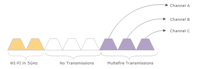
Figure 14: Multefire channel aggregation
The 5G band is sliced in 20 MHz channels. Future versions of Multefire may grow to 100 MHz.
From an IoT architect point of view, Multefire can serve many use cases more effectively than cellular or Wi-Fi. For example, a port may need to track assets like shipping containers and cargo, as well as provide communication to ships arriving and leaving. If the port covers an area of 10 square kilometers, blanket coverage would require 120 small Multefire cells. A Wi-Fi system would require over 500 access points. In this case, the cost of Multefire for deployment alone is a quarter of the cost of Wi-Fi. Cellular coverage would be based on a service agreement and subscription. Depending on the cost of subscription compared to the upfront cost of Multefire deployment and years of amortization, it may be substantially less costly to incorporate a CBRS system like Multefire.
5G
5G (or 5G-NR for New Radio) is the next generation IP-based communication standard being drafted and designed to replace 4G LTE. That said, it draws on some technologies of 4G LTE but comes with substantial differences and new capabilities. So much material has been written on 5G that it dwarfs even current Cat-1 and Cat-M1 material. In part, 5G promises to deliver substantial abilities for IoT, commercial, mobile, and vehicular use cases. 5G also improves bandwidth, latency, density, and user cost.
Rather than build different cellular services and categories for each use case, 5G attempts to be a single umbrella standard to serve them all. Meanwhile, 4G LTE will continue to be the predominant technology for cellular coverage and will continue to evolve. 5G is not a continuing evolution of 4G; it derives from 4G but is a new set of technologies. In this section, we will only discuss elements that are particular to IoT and edge computing use cases.
5G is aiming for initial customer launch in 2020; however, mass deployment and adoption may follow years later in the mid-2020s. The goals and architecture of 5G are still evolving and have been since 2012. There have been three distinct and different goals for 5G (http://www.gsmhistory.com/5g/). Goals include:
- Converged fiber and cellular infrastructure
- Ultra-fast mobiles using small cells
- Lowered cost barriers of mobile
Again, the ITU-R has approved the international specifications and standards, while the 3GPP is following with a set of standards to match the ITU-R timeline. The 3GPP RAN has already begun analyzing study items as of Release 14. The intent is to produce a two-phase release of 5G technologies.
We extend the ITU and 3GPP roadmap for 5G in the graphic below. Here we show a phased roll out of 5G over several years. Release 14 and Release 15 can be considered eLTE eNodeB, which means that an eLTE cell can be deployed as a standalone Next Gen Core or eLTE eNodeB non-standalone.

Figure 15: Expanded view of 3GPP, LTE, and ITU roadmaps for 5G
3GPP has accelerated 5G using a concept termed non-standalone (NSA). NSA reuses the LTE core infrastructure. Conversely, standalone (SA) will rely solely on the 5G Next Generation Core infrastructure.
The World Radio Conference (WRC) meetings at the ITU have allocated the frequency distribution for the initial 5G trials at the WRC-15 meeting. The distribution and use cases for various markets and markets are represented in the following graphic.

Figure 16: ITU WRC goals. Note the decisions around frequency usage and bandwidth. Also note the combination of licensed and unlicensed spectrum for 5G
There are three use case categories for 5G. These use cases have some similar but differentiating features. The same network infrastructure will be designed to support these customers and use cases simultaneously. This will be done through virtualization and network slicing, which is covered later in this chapter.
- Enhanced mobile broadband (eMBB):
- Ultra-reliable and low-latency communications (URLLC):
- Massive machine-type communications (mMTC):
Two primary types of 5G deployments are considered. First is traditional mobile wireless. This uses the sub-2 GHz spectrum and is intended for range, mobility, and power uses. It relies heavily on macrocells and current LTE compatibility. It also must be able to penetrate signals against rain, fog, and other obstacles. The peak bandwidth is toughly 100 MHz.
The second deployment is fixed wireless. This will use frequencies above the 6 GHz range. It relies heavily on new small cell infrastructure and is intended for low-mobility or fixed geographic cases. Range will be limited, as will penetration ability. The bandwidth, however, will be substantial at 400 MHz.

Figure 17: 5G topologies: From left to right: 1 million node density through small cells and macrocell deployment. Indoor and home use of 60 GHz with macrocell at 4 GHz backhaul. Dual connectivity example with split control and data planes using two radios for user data and 4 GHz macrocells for the control plane. Device-to-device connectivity. Massive MIMI with beamforming from a single mmWave antenna. Density increase with a mix of small cells in mmWave for blanket coverage of user data.
5G frequency distribution
Current 4G LTE systems mainly use frequencies below the 3 GHz range. 5G will radically change the spectrum usage. While the space below 3 GHz is significantly congested and sliced into slivers of bandwidth, 5G may use a multitude of frequencies. Under strong consideration is the use of millimeter waves (mmWave) in the unlicensed 24 to 100 GHz range. These frequencies directly address Shannon's Law by increasing the bandwidth B of the law with extremely wide channels. Since the mmWave space is not saturated or sliced up by various regulatory bodies, channels as wide as 100 MHz in the 30 GHz to 60 GHz frequencies are possible. This will provide the technology to support multi Gbps speeds.
The principal issues with mmWave technology are free space path loss, attenuation, and penetration. If we remember that free space path loss can be calculated as Lfs = 32.4 + 20log10f + 20log10R (where f is the frequency and R is the range), then we can see how the loss is affected by a 2.4, 30, and 60 GHz signal as:
- 2.4 GHz, 100 m range: 80.1 dB
- 30 GHz, 100 m range: 102.0 dB
- 60 GHz, 100 m range: 108.0 dB
- 2.4 GHz, 1 km range: 100.1 dB
- 30 GHz, 1 km range: 122.0 dB
- 60 GHz, 1 km range: 128.0 dB
5G-NR allows better efficiency of the spectrum. 5G-NR uses OFDM numerology, but the subcarrier spacing can differ depending on which band is being used. Sub 1 GHz bands may use 15 kHz subcarrier spacing and have less bandwidth but deliver better outdoor macro coverage, whereas mmWave frequencies at 28 GHz can use larger 120 kHz spacing and carry more bandwidth.

Figure 18: 5G differences in subcarrier spacing and bandwidth for different bands (700 to 28 GHz)
20 dB is significant, but with mmWave, antennas can accommodate significantly more antenna elements than a 2.4 GHz antenna. Free path loss is significant only if the antenna gain is independent of frequency. If we keep the antenna area constant, it is possible to mitigate the effects of path loss. This requires Massive-MIMO (M-MIMO) technology. M-MIMO will incorporate macrocell towers with 256 to 1,024 antennas. Beamforming at the macrocell will be used as well. When combined with mmWaves, M-MIMO has challenges in terms of contamination from nearby towers, and multiplexing protocols like TDD will need to be re-architected.
MIMO allows a higher density of UE equipment within an area, but also allows a device to increase bandwidth by receiving and transmitting on more frequencies simultaneously.
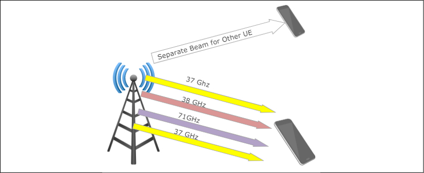
Figure 19: 5G multifrequency beamforming and MIMO allows multiple frequencies and bands to be used simultaneously and directed to a single UE.
Another challenge with 5G is the need for very large antenna arrays to support M-MIMO with hundreds of antennas in a dense tower configuration. Under consideration are tightly packed 3D structures of antennas to support beamforming at the tower. Factors such as wind and storm effects on these towers still need to be resolved.
Attenuation is a very significant issue. At 60 GHz, a signal will be absorbed by oxygen in the atmosphere. Even vegetation and the human body itself will have a serious effect on signals. A human body will absorb so much RF energy at 60 GHz that it will form a shadow. A signal traveling at 60 GHz will have a loss of 15 dB/km. Thus, long-range communication will be subpar using 5G at 60 GHz and will require either a blanket of small cells or a drop to a slower frequency space. This is one of the reasons the 5G architecture will require multiple bands, small cells, macrocells, and a heterogeneous network.
Material penetration in the mmWave spectrum is challenging. mmWave signals attenuate through drywall at 15 dB and glass windows on buildings contribute to a 40 dB loss. Therefore, indoor coverage with a macrocell is close to impossible. This and other types of signaling issues will be mitigated through the widespread use of indoor small cells:

Figure 20: Various frequencies versus penetration loss (dB): Typical building composite materials were tested (glass, brick, wood) from external to internal areas. The loss of infrared reduction glass is particularly difficult for mmWave frequencies.
UEs may use multiple bands simultaneously. For example, an endpoint device may use lower frequencies for long-range communication and switch to mmWave for indoor and personal communication. Another scheme being considered is dual connectivity, which steers data traffic across multiple bands dependent on data type. For example, the control plane and user plane of the stack are already divided. User plane data may steer to a nearby small cell using a 30 GHz frequency, whereas control data may be steered to a long-range eNodeB macrocell tower at the typical 4 GHz rate.
Another improvement for increased speed is spectral efficiency. The 3GPP is focusing on certain design rules:
- 15 kHz subcarrier spacing to improve multiplexing efficiency
- Flexible and scalable numerology of symbols from 2M symbols to 1 symbol to reduce latency
As previously discussed, spectral efficiency is given in units of bps/Hz. Using D2D and M-MIMO along with changes to the air interface and new radio one can improve spectral efficiency. 4G LTE uses OFDM, which works well for large data transmissions. However, for IoT and mMTC, the packets are much smaller. The overhead for OFDM also impacts latency in very dense IoT deployments. Hence, new waveforms are being architected for consideration:
- Non-orthogonal multiple access (NOMA): Allows multiple users to share a wireless medium
- Filter Bank Multicarrier (FBMC): Controls the shape of subcarrier signals to remove side-lobes through DSPs
- Sparse code multiple access (SCMA): Allows data to be mapped to different code from different codebooks.
Latency reduction is also a goal of the ITU and 3GPP. Latency reduction is crucial for 5G use cases such as interactive entertainment and virtual reality headsets, but also for industrial automation. However, it plays a large role in power reduction (another ITU goal). 4G LTE can have a latency of up to 15 ms on 1 ms subframes. 5G is preparing for sub-1 ms latency. This too will be accomplished using small cells to marshal data rather than congested macrocells. The architecture also plans for device-to-device (D2D) communication, essentially taking the cell infrastructure out of the data path for communication between UEs.
4G systems will continue to exist, as the rollout of 5G will take several years. There will be a period of coexistence that needs to be established. Release 15 will add further definitions to the overall architecture such as channel and frequency choices. From an IoT architect perspective, 5G is a technology to watch and plan for. IoT devices may predicate a WAN that will need to operate for a dozen years or more in the field. For a good perspective on the key points, constraints, and the detailed design of 5G, readers should refer to 5G: A Tutorial Overview of Standards, Trials, Challenges, Deployment, and Practice, by M. Shafi et al., in IEEE Journal on Selected Areas in Communications, vol. 35, no. 6, pp. 1201-1221, June 2017.
5G RAN architecture
The 5G architecture and stack evolves from the 4G standards. This section examines the high-level architectural components, decomposition, and trade-offs of different 5G designs.
The interface between the radio unit (RU) and distribution unit (DU) has been the legacy CPRI fiber interface. New types of interfaces based on different architectures are in consideration as we will examine later in this chapter. CPRI is a vendor proprietary serial interface with bandwidth of 2.5 Gbps.
Enhanced CPRI or e-CPRI is an alternate interface for 5G based on open standards without vendor lock-in. e-CPRI also allows for the functional split architecture described later and decomposing the network using IP or Ethernet standards versus IQ over CPRI.
The 5G architecture is designed for flexibility and regional infrastructure. For example, regions in Asia have extensive preexisting fiber, but North America and Europe do not. The RAN architecture has been designed to be flexible so it can be deployed without fiber infrastructure. This requires different connectivity options. As mentioned, 5G will rely on traditional 4G LTE infrastructure, which was not designed for the capacity or speed of 5G. The non-standalone versions will differ more in architecture than standalone systems. For flexibility, the architecture is fungible. For example, the traditional interface between the DU and RU is the CPRI interface. The CPRI interface requires a dedicated link to each antenna. Since 5G is based on MIMO technology, it exacerbates the bandwidth issue. Take a 2x2 MIMO antenna that is using three vectors. This requires 2*2*3=12 CPRI channels or wavelengths for just one antenna. The actual number of MIMO antennas will be much higher in 5G towers. CPRI simply cannot scale to the capacity and demand. Therefore, we introduce the notion of "functional splits" between layers 1, 2 and/or 3 of the cell network. We have flexibility as to which functions reside where in the architecture and respective systems. The following graphic illustrates some options as to where the split would occur between the RU and BBU.

Figure 21: Flexible configuration of using "functional splits" of the 5G RAN between the baseband unit and radio unit. Note the difference in data rates. Moving more functionality to the RU places a higher level of processing burden on each radio and decreases the overall speed, whereas moving more functionality to the BBU will place significant stress on the CPRI interface but provide the fastest speeds.
The other factor contributing to this functional decomposition is the added latency of CPRI. The distance between a cell tower and a DU can extend to 10 km. This added latency on top of addition compute at the RU can be adversarial to certain 5G applications like AR/VR and streaming video. This causes a juxtaposition in architecture. Either reduce latency with additional compute at the BBU/DU and use bandwidth-hungry CPRI, or move more processing to the RU, which will reduce latency but decrease bandwidth.
The baseband unit (BBU), sometimes called the central unit or CU, is a logical node responsible for transfer of data, mobility control, radio access network sharing, positioning, and session management. The BBU controls all DU operations under its service management through the fronthaul interface.
The DU, sometimes called the remote radio head (RRH), is also a logical node and provides a subset of the gNB functionality. Functionality can be split so what resides where can be dynamic. Its operations are controlled by the BBU.
As can be seen in the diagram, the middle tiers of the 5G architecture allow what is termed multi-access edge computing, or MEC. This topic will be covered later in the edge computing chapter, but essentially it allows applications that are not communication and carrier focused to coexist on common edge hardware through virtualization interfaces. It brings cloud computing closer to the edge and end users or to data sources that need higher bandwidth or lower latency than what can be provided through multiple network hops to a traditional cloud service.
5G Core architecture
The 5G Core (or 5GC) is a service-based architecture based on different network functions. These functions either exist in the 5GC exclusively or have interfaces and connections to the RAN via the control plane. This differs from legacy 4G LTE where all of the core functionality had a common reference point. References points still exist within the user plane, but functions like authentication and session management will be services.
The architecture is organized as follows:
- Authentication Credential Repository (ARPF/UDM): Responsible for storing long-term security credentials and resides in the operator's home network.
- Authentication Server Function (AUSF): Interacts with ARPF and terminates requests from the SEAF. It resides in the operator's home network.
- Security Anchor Function (SEAF): Receives intermediate key from AUSF. This is the security system of the core network. SEAF and AMF must be collocated, and there must be a single anchor point for each PLMN.
- Policy Control Function (PCF): Analogous to the existing 4G LTE policy and Charging Rules Function (PCRF).
- Session Management Function (SMF): Identifies idle and active sessions. It allocates IP addresses to UE devices, manages IP addresses, and adapts policy and offline/online charging interface termination.
- User Plane Function (UPF): Configures the network for a reduction in overall latency. It sets the anchor point of intra- and inter-RAT mobility. The UPF also bears the external IP address for interconnect. Additionally, it manages packet routing, packet forwarding, and user plan QoS.
- Application Functions (AF): Additional services trusted by the carrier. These services can be provisioned to access network functions directly.
- Data Network (DN): Generally outward Internet access but also direct operator services and third-party services.
These core services are designed to be cloud-aligned and cloud-agnostic meaning that the services can exist through multiple vendors. However, a fundamental difference between 5G and 4G LTE is the addition of user plane functions (UPF) in 5G. These are intended to decouple packet gateway control from the user plane of data. This again takes from SDN architectures.

Figure 22: 3GPP conceptual picture of 5GC architecture
5G security and registration
Aside from new security capabilities using NFV and virtualization, 5G improves on security through unified authentication. This is termed a unified authentication framework. This technology decouples authentication from access points. Additionally, it allows extensible authentication algorithms, adaptable security policies, and the use of subscriber permanent identifiers (SUPI).
SUPI starts the process by creating a subscriber concealed identifier (SUCI). The concealing can be performed in the UE SIM card if present or in the UE equipment if not present.

Figure 23: Top-level diagram of 5G security actors
When a UE wants to register with a network, it first sends a registration request. This message includes all the information elements (IE) and other details needed to identify the device. The AMF/SEAF (Authentication Server Function and Security Anchor Function) will prepare an Authentication Initiation Request (5G-AIR) and send it to the AUSF. The AUSF resides in the home network while the SEAF resides in the service network.
After the AUSF receives and validates the 5G-AIR message, it will generate an Auth-Info-Req message and marshal the data to the UDM/ARPF (Authentication Credential Repository). Here the authentication vector is generated and the SUPI response is delivered back to the AMF layer.
A generalized view of this transaction is illustrated in the following figure:
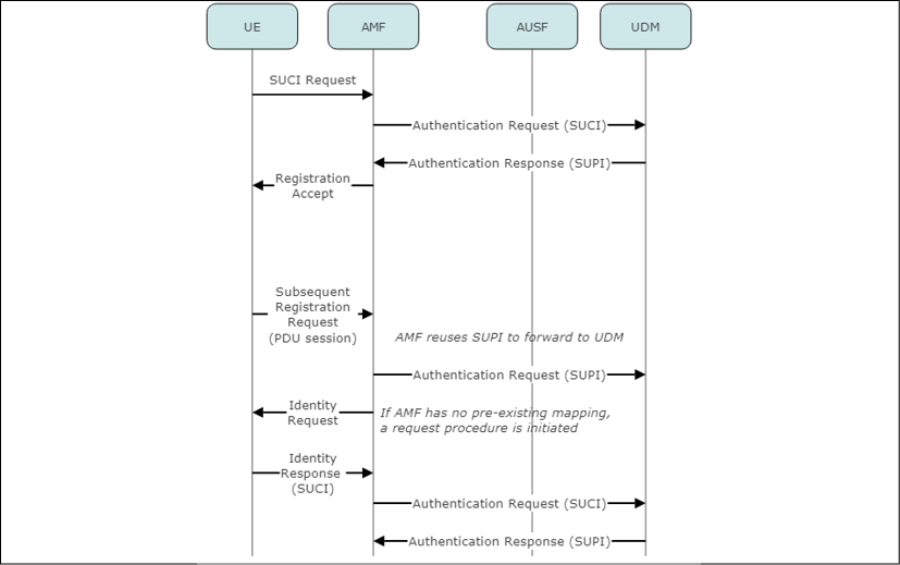
Figure 24: Typical process flow for 5G authentication and security exchange. After the SUCI frame is sent to the UDM, its response is either accepted or denied via the SUPI authentication response. All new registrations may reuse the same SUPI if the mapping already exists
Ultra-Reliable Low-Latency Communications (URLCC)
One of the three use cases of 5G is low-latency communication and high reliability. These services would be tailored for high-value and life-critical situations like remote surgery, drones, or public safety systems. These systems have hard real-time dependencies and must respond to a signal within a specified time. Think of an autonomous car that needs to respond to a braking command in real time. To meet this requirement, the designers have altered the physical scheduler and channel encoder. Essentially all URLCC traffic can preempt all other forms of traffic. Uplink communication can reduce its latency through better channel encoding schemes. These schemes involve the ability to decode multiple uplink transmissions simultaneously. Retransmissions are another notorious factor in impacting latency. Low-latency HARQ is a method incorporated into 5G to resolve the retransmission performance impact. We will cover HARQ later in the chapter. Finally, reliability of the signal is enhanced using shortened blocks in the channel coding as well as increasing the diversity and mix of blocks.
The following illustration is of flexible slot-based 5G-NR traffic. eMBB, mMTC, and URLCC traffic will coexist in the same frequency and time space. However, only URLCC traffic has the ability to preempt all other traffic classes by injecting URLCC symbols into the same channels as other traffic sources. Refer to J. Hyoungju et. al., Ultra Reliable and Low Latency Communications in 5G Downlink: Physical Layer Aspects, IEEE Wireless Communications Vol 25, No 3. 2018.
This technique allows for scalable slot durations where multiplexing of traffic of different types, durations, and QoS requirements coexist. The slot structure itself is self-contained. This means that the ability to decode slots and avoid static timing relationships stretches across all slots.

Figure 25: Multiple traffic types can coexist seamlessly in 5G transmissions across multiple frequencies and variable time spaces. Notice the URLCC structure spreads across all frequencies simultaneously. URLCC also can be injected at any time in the sequence to achieve its goal of 1 ms latency. Also note the transmission times are not equal or fixed length. The transmission time intervals (TTI) are scalable, dynamic, and variable.
Fine-grain time-division duplexing (TDD) and low-latency HARQ
HARQ stands for hybrid automatic repeat request. This is another 5G-specific change from LTE systems to support low-latency requirements of URLCC. LTE-Advanced does have the concept of HARQ and allows for a round trip time (RTT) of ~10 ms. URLCC, as stated by 3GPP, is targeted to 1 ms. To accomplish this 10x improvement in latency, 5G permits slot reorganization of the carrier signal. This is termed fine-grain TDD.
5G allows for efficient multiplexing of mission critical data with other services. This was discussed in the last section. The HARQ design allows for the injection of URLCC traffic at any time in the overall sequence and flow of data.
The transmission time is also scalable and flexible. The Transmission Time Interval (TTI) is no longer fixed. The TTI can be tuned shorter for low latency and highly reliable communications, or it can be lengthened for higher spectral efficiency. Multiple traffic types and different TTI lengths can coexist in the same dataflow. Long TTIs and short TTIs can be multiplexed to allow transmissions to start on symbol boundaries.

Figure 26: Illustrating the different in TDD retransmission. In 4G LTE, a retransmission could incur a large latency penalty of up to 10 ms. 5G URLLC TDD can reduce the round-trip time (RTT) and overall latency by acknowledging data received in the same subframe. Since the TTI is variable, this can be accomplished. Here we illustrate the NAK of the first packet can be transmitted almost immediately after reception.
The URLCC packet also can be scheduled abruptly. 3GPP recommends two solutions to schedule this packet:
- Instant scheduling: This allows an existing transmission to interrupt and then to initiate a URLCC packet.
- Reservation-based scheduling: Here, URLCC resources are reserved prior to data scheduling. A base station may broadcast a new scheduling policy and frequency numerology. As an example, the base station may select 14 OFDM symbols for eMBB traffic but guarantee 4 of the symbols will be for URLCC traffic. If no traffic exists, the bandwidth would be wasted.
Network slicing
Part of the architecture of 5G involves decoupling the control and data plane technology stacks common in current cellular architecture. Network slicing involves the use of software-defined networking (SDN) and network function virtualization (NFV). These are types of network virtualization designs common in enterprise, data centers, and hyperscale implementations. Network virtualization techniques allow easier flexibility of hardware for service providers, methods to sell or partition services differently for customers, and the ability to move and route data on shared physical infrastructure but present the service as a trusted private network. A deep dive into SDN architecture will be presented in the edge routing chapter.
In short, SDN separates the control plane, which manages the routing of a network, from the data plane, which handles the forwarding of information. NFV virtualizes network applications like deep packet inspection and security services. Rather than bind these features into a single vendor-specific hardware device, we can break out these functions and even run services in the cloud. These technologies allow very fast and adaptive network changes based on subscriptions, security, and demand.
For 5G, network slicing enables:
- The ability to create virtual subnets over existing private and shared infrastructure
- End-to-end tailored networks
- Controlled and adaptive quality of service and provisioning methods
- Dynamic load adjustment for specific traffic types
- Fee-based subscription models and SLAs for faster or lower latency services
From the IoT architecture point of view, slicing becomes an option or a necessity dependent on how 5G is used and consumed by the product and deployment. In a virtual use case, a network slice can be provisioned through an SLA for premium service, low-latency guarantee, higher bandwidth, or secure dedicated networking. IoT devices that are immobile or require high bandwidth can be provisioned for services specific to their use case on the same 5G network infrastructure.
In 4G LTE systems, many of the components in the RAN (DU) and Core used OEM-specific hardware. This prevents the ability to customize and tailor communications traffic to customers and use cases efficiently.
5G migrates to virtualized infrastructure and SDN, allowing flexibility and adaptability in network design.

Figure 27: 5G network slicing. 4G LTE systems at the top of the illustration show a linear flow from UE to Core using dedicated OEM-specific equipment and software. Provisioning dependent on UE use case is not an option in 4G LTE, whereas 5G allows for service-level network slicing. Here the edge systems can divide and provision services based on customer needs and SLAs. Services can migrate from cloud to edge dynamically via software-defined infrastructure.
5G energy considerations
A consideration when using 5G (or any wireless protocol) is the energy it consumes not only on the client device but also the server infrastructure such as an eNodeB. As 5G can theoretically deliver 1,000 times as much data as previous cellular architectures and density, it does this with a cost in energy.
First, the architect must consider that 5G is built on a massive scale of small-cell systems rather than large towers. Small cells will operate at lower power than traditional cellular systems, but the sheer volume of them will contribute to larger energy density.
A secondary problem is the use of MIMO in 5G. 5G-NR, as stated earlier, is based on a phased roll out and makes use of existing 4G LTE infrastructure. Part of that includes the use of orthogonal frequency-division multiplexing (OFDM). OFDM will divide a transmitting portion of data on different frequencies simultaneously. This is what gives the technology the basis of being "orthogonal." However, this ability to spread into multiple frequencies has a side effect called peak-to-average power ratio (PAPR). OFDM is known to have a very high PAPR (A. Zaidi, et. al. Waveforms and Numerology to 5G Services and Requirements, Ericsson Research, 2016). To allow OFDM to work, a receiver of an OFDM signal must be capable of absorbing the combined energy of multiple frequencies and a transmitter must be capable of generating and broadcasting that energy. PAPR is the relation of the maximum power of a sample for a given OFDM symbol to the average power of that symbol as measured in dB.
Release 15 from 3GPP standardized on OFDM as the encoding method as it was used on 4G LTE.
An example of the power can be shown by an example. If a transmitter produces a signal at 31 dBm, that is equivalent to 1.259 W of power. If the PAPR is 12 dB, then the saturation point is 31 dBm + 12 dBm = 43 dBm. This is equivalent to 19.95 W.
What this means to IoT devices is the potential for significant degradation in battery life and increase in power usage. A transceiver radio never operates at 100% efficiency converting DC power to RF energy. Nearly 30% of a transceiver's power is lost to heat and power amplifier inefficiencies. The effect of PAPR means that the power amplifier will need to reduce its operational power to compensate for the peak power bursts of MIMO.
There are techniques to mitigate the effects of PAPR:
- Clipping: This is essentially the removal of part of the signal that exceeds the permitted area. This technique causes distortion. Likewise, it increases bit error rates and reduces spectral efficiency, but is easiest to implement.
- SLM: This technique uses different symbol sequences generated by multiplying the transmitted data with the phase sequence. The one with the minimal PAPR is transmitted. It can be overly complex to implement. There is no distortion, but it causes a reduction in data rates.
- PTS: This method generates extra encoded information sent to the receiver to assist in determining the best possible phase factors. It can be overly complex to implement. There is no distortion, but it causes a reduction in data rates.
- Non-orthogonal multiple access: This serves multiple UEs on the same time/frequency resources either through power domain multiplexing or code domain multiplexing. This is contrary to OFDM, which is entirely a frequency domain multiplexing scheme. The primary issue with this method is it breaks compatibility with 4G LTE and will incur a considerable cost to transform every base station and small cell. It also has challenges with complexity and a reduction in the number of users serviced simultaneously.
This effect on power versus performance and density should be considered by the architect when considering and/or deploying 5G for an IoT use case versus other standards.
LoRa and LoRaWAN
LPWAN also includes technologies that are proprietary and not sponsored by 3GPP. It can be argued that some IEEE 802.11 protocols should also be classified in LPWAN, but the next two sections will highlight LoRa and Sigfox. LoRa is a physical layer for a long-range and low-power IoT protocol while LoRaWAN represents the MAC layer.
These proprietary LPWAN technologies and carriers have the advantage of using the unlicensed spectrum and that, simply, is data plan cost.
LoRa/LoRaWAN can be built, customized, and managed by anyone. There is no carrier or service-level agreement if you choose not to use a carrier. LoRa and LoRaWAN offer a degree of flexibility only seen in CBRS and Multefire. It is important to understand the monetization impact on scaling when building an architecture using any communication.
Typically, technologies like Sigfox and LoRaWAN will be 5x to 10x lower in their data rates compared to traditional 3G or LTE connections for large volume deployments (>100,000 units). That may change with more competition from Cat-M1, Cat-NB, and Cat-5, but it is too early to tell.
The architecture was originally developed by Cycleo in France but then acquired by the Semtech Corporation (a French mixed-signal electronics manufacturer) in 2012 for $5 million in cash. The LoRa Alliance was formed in March of 2015. The alliance is the standard body for the LoRaWAN specification and technology. They also have a compliance and certification process to ensure interoperability and conformity to the standard. The alliance is supported by IBM, Cisco, and over 160 other members.
LoRaWAN has gained traction in Europe with network deployments by KPN, Proximus, Orange, Bouygues, Senet, Tata, and Swisscom. Other areas have sparse coverage to date.
One reason for the price difference, besides being in the unlicensed spectrum, is that a single LoRaWAN gateway has the potential to cover a significant amount of area. Belgium, with a land area of 30,500 km2, is completely covered by seven LoRaWAN gateways. Typical range is 2 to 5 km in urban areas and 15 km in suburban areas. This reduction in infrastructure cost is very different than 4G LTE with much smaller cells.
Since LoRa is the bottom of the stack, it has been adopted in architectures competing with LoRaWAN. Symphony Link, for example, is Link Labs's LPWAN solution based on the LoRa PHY, using an eight-channel, sub-GHz base station for industrial and municipal IoT deployments. Another competitor using LoRa is Haystack, which produces the DASH7 system. DASH7 is a full network stack on the LoRa PHY (not just the MAC layer).
The next section will focus exclusively on LoRaWAN.
LoRa physical layer
LoRa represents the physical layer of a LoRaWAN network. It manages the modulation, power, receiver and transmission radios, and signal conditioning.
The architecture is based on the following bands in ISM license-free space:
- 915 MHz: In the USA with power limits but no duty cycle limit
- 868 MHz: In Europe with a 1% and 10% duty cycle
- 433 MHz: In Asia
A derivative of chirp spread spectrum (CSS) is the modulation technique used in LoRa. CSS balances data rate with sensitivity in a fixed channel bandwidth. CSS was first used in the 1940s for military long-range communication by using modulated chirp pulses to encode data and was found to be especially resilient against interference, Doppler effects, and multipath. Chirps are sinusoidal waves that increase or decrease over time. Since they use the entire channel for communication, they are relatively robust in terms of interference. We can think of chirp signals with increasing or decreasing frequencies (sounding like a whale call). The bitrate LoRa uses is a function of the chirp rate and the symbol rate. The bitrate is represented by Rb, the spreading factor by S, the bandwidth by B.
Therefore, the bitrate (bps) can range from 0.3 kbps to 5 kbps and is derived as:

This form of modulation allows for low power over long distances, as the military found. Data is encoded using the increasing or decreasing frequency rate and multiple transmissions can be sent with different data rates on the same frequency. CSS allows signals to be received at 19.4 dB below the noise floor using FEC. The band is also subdivided into multiple sub-bands. LoRa uses 125 kHz channels and dedicates six 125 kHz channels and pseudorandom channel hopping. A frame will be transmitted with a specific spreading factor. The higher the spreading factor, the slower the transmission but the longer the transmission range. The frames in LoRa are orthogonal, meaning multiple frames can be sent simultaneously as long as each is sent with a different spreading factor. In total there are six different spreading factors (SF = 7 to SF = 12).
The typical LoRa packet contains a preamble, header, and 51- to 222-byte payload.
LoRa networks have a powerful feature called Adaptive Data Rate (ADR). Essentially this enables dynamically scalable capacity based on the density of nodes and infrastructure.
ADR is controlled by the network management in the cloud. Nodes that are close to a base station can be set to a higher data rate because of signal confidence. Those nodes in close proximity can transmit data, release their bandwidth, and enter a sleep state quickly versus distant nodes which transmit at slower rates.
The following table describes the uplink and downlink features:
| Feature | Uplink | Downlink |
|
Modulation |
CSS |
CSS |
|
Link budget |
156 dB |
164 dB |
|
Bitrate (adaptive) |
0.3 to 5 kbps |
0.3 to 5 kbps |
|
Message size per payload |
0 to 250 bytes |
0 to 250 bytes |
|
Message duration |
40 ms to 1.2 s |
20 to 160 ms |
|
Energy spent per message |
Etx = 1.2s * 32 mA = 11 µAh at full sensitivity Etx = 40 ms * 32 mA = 0.36 µAh at min sensitivity |
Etx=160 ms * 11 mA = 0.5 µAh |
LoRaWAN MAC layer
LoRaWAN represents the MAC that resides on top of a LoRa PHY. The LoRaWAN MAC is an open protocol, whereas the PHY is closed. There are three MAC protocols that are part of the data link layer. These three protocols balance latency with energy usage. Class-A is the best for energy mitigation while having the highest latency. Class-B is between Class-A and Class-C. Class-C has the minimum latency but the highest energy usage.
Class-A devices are battery-based sensors and endpoints. All endpoints that join a LoRaWAN network are first associated as Class-A with the option of changing class during operation. Class-A optimizes power by setting various receive delays during transmission. An endpoint starts by sending a packet of data to the gateway. After the transmission, the device will enter a sleep state until the receive delay timer expires. When the timer expires, the endpoint wakes and opens a receive slot and awaits a transmission for a period of time and then reenters the sleep state. The device will wake again as another timer expires. This implies that all downlink communication occurs during a short period of time after a device sends a packet uplink. However, that time-period can be an extremely long time.
Class-B devices balance power and latency. This type of device relies on a beacon being sent by the gateway at regular intervals. The beacon synchronizes all endpoints in the network and is broadcast to the network. When a device receives a beacon, it creates a ping slot, which is a short reception window. During these ping slot periods, messages can be sent and received. At all other times, the device is in a sleep state. Essentially this is a gateway-initiated session and based on a slotted communication method.
Class-C endpoints use the most power but have the shortest latency. These devices open two Class-A receive windows as well as a continuously powered receive window. Class-C devices are usually powered on and may be actuators or plug-in devices. There is no latency for the downlink transmission. Class-C devices cannot implement Class-B.
The LoRa/LoRaWAN protocol stack can be visualized as follows:

Figure 28: The LoRa and LoRaWAN protocol stack compared with a standard OSI model. Note: LoRa/LoRaWAN represents only layer 1 and layer 2 of the stack model
LoRaWAN security encrypts data using the AES128 model. One difference in its security compared to other networks is that LoRaWAn separates authentication and encryption. Authentication uses one key (NwkSKey), and user data a separate key (AppSKey). To join a LoRa network, devices will send a JOIN request. A gateway will respond with a device address and authentication token. The application and network session keys will be derived during the JOIN procedure. This process is called the Over-the-Air-Activation (OTAA). Alternatively, a LoRa-based device can use Activation by Personalization (ABP). In this case, a LoRaWAN carrier/operator preallocates 32 bits of network and session keys. A customer will purchase a connectivity plan and obtain a set of keys from an endpoint manufacturer with the keys burned into the device.
LoRaWAN is an asynchronous, ALOHA-based protocol. The pure ALOHA protocol was initially devised at the University of Hawaii in 1968 as a form of multiple access communication before technologies such as CSMA existed. In ALOHA, clients can transmit messages without knowing if other clients are in the process of transmitting simultaneously. There are no reservations or multiplexing techniques. The basic principle is the hub (or gateway in the case of LoRaWAN) immediately retransmits packets it has received. If an endpoint notices one of its packets was not acknowledged, it will wait and then retransmit the packet. In LoRaWAN, collisions only occur if transmissions use the same channels and spreading factor.
LoRaWAN topology
LoRaWAN is based on a star network topology. LoRa communication is also based on broadcasting rather than establishing a peer-to-peer relationship. For that matter, it can be said it supports a star of stars topology. Rather than a single hub-spoke model, a LoRaWAN can assume multiple gateways. This allows improved networking ability and range. It also implies that a cloud provider may receive duplicate messages from multiple gateways. The responsibility is placed upon the cloud provider to manage and deal with duplicate broadcasts.
A critical component of LoRaWAN that sets it apart from most of the transports listed in this book is the fact that user data will be transported from an end-node to the gateway over the LoRaWAN protocol. At that point, the LoRaWAN gateway will forward the packet over any backhaul (such as 4G LTE, Ethernet, or Wi-Fi) to a dedicated LoRaWAN network service in the cloud. This is unique because most other WAN architectures release any control of customer data at the time it leaves their network to a destination on the Internet.
The network service has the rules and logic to perform the necessary upper layers of the network stack. A side effect of this architecture is that a handoff from one gateway to another isn't necessary as it is in LTE communication. If a node is mobile and moves from antenna to antenna, the network services will capture multiple identical packets from different paths. These cloud-based network services allow LoRaWAN systems to choose the best route and source of information when an end-node is associated with more than one gateway. Responsibilities of the network services include:
- Duplicate packet identification and termination security services
- Downlink routing
- Acknowledgement messages
Additionally, LPWAN systems like LoRaWAN will have 5x to 10x fewer base stations for similar coverage to a 4G network. All base stations are listening to the same frequency set; therefore, they are logically one very large base station.
This, of course, reinforces the statement that LPWAN systems can be a lower cost point than a traditional cellular network:

Figure 29: LoRaWAN network topology: LoRaWAN is built on a star of star type topology with gateways acting as the hubs as well as communication agents over traditional IP networks to LoRaWAN administration in the cloud. Multiple nodes can associate with multiple LoRaWAN gateways.
LoRaWAN summary
LoRaWAN is a Long Range wide area network energy saver. It is one of the most suitable technology for objects using batteries. Its transmission distance and penetration make it very suitable for smart city usage (streetlights, parking place detectors, and so on), which is a key IoT application. However, it indeed has a low data rate and limited payload, and duty cycle regulation may not meet application requiring real-time communication.
LoRaWAN does have gaps in the architecture and protocols that need careful consideration from the IoT architect:
- Some features common in LTE networks are simply not designed into the LoRaWAN architecture. LoRaWAN is not a complete network stack in the OSI model. It lacks the common features of a network layer, session layer, and transport layer: roaming, packetizations, retry mechanisms, QoS, and disconnects. It is up to the developer and integrator to add those services if necessary.
- LoRaWAN relies on a cloud-based network interface. At some point in the value chain, a cloud subscription is needed.
- The chip vendor is Semtech, which is the single source of the technology, although there have been announced partnerships with ST Microelectronics. This is similar to the Z-Wave value chain.
- LoRaWAN is based on the ALOHA protocol. ALOHA complicates validation and acknowledgment and contributes to error rates over 50%.
- Downlink ability is still limited. In certain use cases that is sufficient, but it tempers flexibility.
- LoRaWAN has high latency and no real-time ability.
- Very slow OTA firmware updates.
- Mobility and moving nodes are challenging to manage in LoRaWAN. A 40- to 60-byte message can take 1 to 1.5 s to transmit. This can be problematic for moving vehicles at highway speed.
- A LoRa base station also needs to be linear time invariant (LTI), which means the radio waveform shouldn't change the time of flight.
- Geolocation precision is about 100 m. Using RSSI signal strength measurements or time-of-flight measurements, a degree of accuracy can be obtained. The best solution is for three base stations to triangulate a node. More base stations can improve the accuracy.
Sigfox
Sigfox is a narrowband LPWAN (like NB-IoT) protocol developed in 2009 in Toulouse, France. The founding company goes by the same name. This is another LPWAN technology using the unlicensed ISM bands for a proprietary protocol. Sigfox has some traits that significantly narrow its utility:
- Up to 140 messages per device daily on uplink (duty cycle of 1%, 6 messages/hour).
- A payload size of 12 bytes for each message (uplink) and 8 bytes (downlink). A throughput of up to 100 bps uplink and 600 bps downlink.
Originally, Sigfox was unidirectional and intended as a pure sensor network. That implies that only communication from the sensor uplink was supported. Since then a downlink channel has become available.
Sigfox is a patented and closed technology. While their hardware is open, however, the network is not and requires a subscription. Sigfox hardware partners include Atmel, TI, Silicon Labs, and others.
Sigfox builds and operates its network infrastructure similar to the arrangement of LTE carriers. This is a very different model than LoRaWAN. LoRaWAN requires a proprietary hardware PHY be used on their network, whereas Sigfox uses several hardware vendors but a single managed network infrastructure. Sigfox calculates rates by the number of devices that are connected to a customer's network subscription, the traffic profile per device, and the duration of the contract.
While there are strict limitations of Sigfox in terms of throughput and utilization, it is intended for systems sending small and infrequent bursts of data. IoT devices like alarm systems, simple power meters, and environmental sensors would be candidates. Data for various sensors can typically fit within the constraints, such as temperature/humidity data represented in 2 bytes with 0.004-degree precision. You must be careful with the degree of precision the sensor provides and the amount of data that can be transmitted. One trick to use is state data; a state or event can simply be the message without any payload. In that case, it consumes 0 bytes. While this doesn't eliminate the restrictions in broadcasting, it can be used to optimize for power.
Sigfox physical layer
As mentioned previously, Sigfox is ultra-narrowband (UNB). As the name implies, the transmission uses a very narrow channel for communication. Rather than spreading the energy across a wide channel, a narrow slice of that energy is confined to these bands:
- 868 MHz: Europe (ETSI 300-200 regulations)
- 902 MHz: North America (FCC part 15 regulations)
Some regions such as Japan have strict spectral density limitations currently making ultra-narrowband difficult to deploy.
The band is 100 Hz in width and uses Orthogonal Sequence Spread Spectrum (OSSS) for the uplink signal and 600 Hz using Gaussian frequency-shift keying (GFSK) for the downlink. Sigfox will send a short packet on a random channel at a random time delay (500 to 525 ms). This type of encoding is called random frequency and time-division multiple access (RFTDMA). Sigfox, as stated, has strict parameters of use, notably data size limitations. The following table highlights these parameters for the uplink and downlink channels:
| Uplink | Downlink | |
| Payload limit (bytes) |
12 |
8 |
| Throughput (bps) |
100 |
600 |
| Maximum messages per day |
140 |
4 |
| Modulation scheme |
DBPSK |
GFSK |
| Sensitivity (dBm) |
<14 |
<27 |
Bidirectional communication is an important characteristic of Sigfox versus other protocols. However, bidirectional communication in Sigfox does require some explanation. There is no passive reception mode, meaning a base station cannot simply send a message to an endpoint device at any time. A receive window opens for communication only after the transmission windows complete. The receive window will open only after a 20-second period after the first message was sent by an endpoint node. The window will remain open for 25 seconds, allowing reception of a short (4 byte) message from a base station.
333 channels, each 100 Hz in width, are used in Sigfox. The receiver sensitivity is -120 dBm/-142 dBm. Frequency hopping is supported using a pseudorandom method of 3 out of the 333 channels. Finally, the transmission power is specified to be +14 dBm and +22 dBm in North America:

Figure 30: Sigfox transmission timeline: Three copies of the payload are transmitted on three unique random frequencies with various time delays. A window for downlink transmission opens only after the last uplink.
Sigfox MAC layer
Each device in a Sigfox network has a unique Sigfox ID. The ID is used for the routing and signing of messages. The ID is used to authenticate the Sigfox device. Another characteristic of Sigfox communication is that it uses fire and forget. Messages are not acknowledged by the receiver. Rather, a message is sent three times on three different frequencies at three different times by the node.
This assists in ensuring the integrity of transmission of a message. The fire-and-forget model has no way of ensuring the message was actually received, so it is up to the transmitter to do as much as possible to ensure accurate transmission:
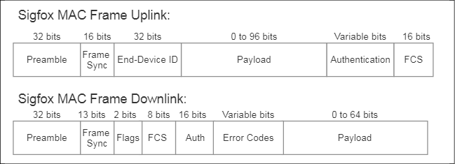
Figure 31: Sigfox MAC frame packet structure for uplink and downlink
The frames contain a preamble of predefined symbols used for synchronization in transmission. The frame sync fields specify the types of frames being transmitted. The frame check sequence (FCS) is used for error detection.
No packet contains a destination address or other node. All data will be sent by the various gateways to the Sigfox cloud service.
The data limit can be understood and modeled from the MAC layer packet format:
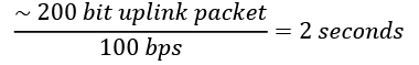
Given each packet is transmitted three times, and we know that European regulations (ETSI) limit transmission to a 1% duty cycle, we can calculate the number of messages per hour using the maximum payload size of 12 bytes:
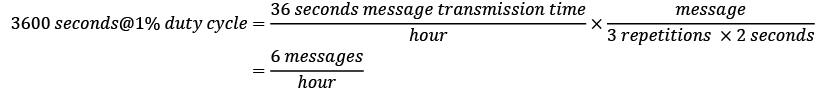
Even though 12 bytes is the limit of a payload, that message may take over one second to transmit. Early versions of Sigfox were unidirectional, but the protocol now supports bidirectional communication.
Sigfox protocol stack
The protocol stack is similar to other stacks following the OSI model. There are three levels, detailed here:
- PHY layer: Synthesizes and modulates radio signals using DBPSK in the uplink direction and GFSK in the downlink direction as previously detailed.
- MAC layer: Adds fields for device identification/authentication (HMAC) and error correcting code (CRC). The Sigfox MAC does not provide any signaling. This implies that devices are not synchronized with the network.
- Frame layer: Generates the radio frame from application data. Also, it systematically attaches a sequence number to the frame:
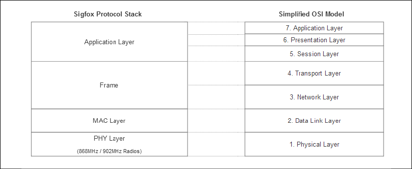
Figure 32: The Sigfox protocol stack versus the simplified OSI model
With regards to security, messages are not encrypted anywhere in the Sigfox protocol stack. It is up to the customer to provide an encryption scheme to the payload data. No keys are exchanged over a Sigfox network; however, each message is signed with a key unique to the device for identification.
Sigfox topology
A Sigfox network can be as dense as one million nodes per base station. The density is a function of the number of messages sent by the network fabric. All nodes that attach to a base station will form a star network.
All data is managed through the Sigfox backend network. All messages from a Sigfox base station must arrive at the backend server through IP connectivity. The Sigfox backend cloud service is the only destination for a packet.
The backend will store and send a message to the client after authenticating it and verifying there are no duplicates. If data needs to be transmitted to an endpoint node, the backend server will select a gateway with the best connectivity to the endpoint and forward the message on the downlink. The backend has already identified the device by packet ID, and prior provisioning will force the data to be sent to a final destination. In a Sigfox architecture, a device cannot be directly accessed.
Neither the backend nor the base station will directly connect to an endpoint device.
The backend is also the administration, licensing, and provide service for customers. The Sigfox cloud routes data to the destination the customer chose. The cloud service offers APIs via a pull model to integrate Sigfox cloud functions in a third-party platform. Devices can be registered through another cloud service. Sigfox also offers callbacks to other cloud services. This is the preferred method to retrieve data:

Figure 33: Sigfox topology: Sigfox utilizes its proprietary non-IP protocol and converges the data to a Sigfox network backend as IP data.
To assist with ensuring data integrity of the fire-and-forget communication model, multiple gateways may receive a transmission from a node; all the subsequent messages will be forwarded to the Sigfox backend and duplicates will be removed. This adds a level of redundancy to the reception of data.
Attaching a Sigfox endpoint node is intended to ease installation. There is no pairing or signalization.
Summary
While there is some commonality between the types of long-range communication technologies, they also are targeting different use cases and segments. The IoT architect should choose wisely which long-range system they intend to adopt. Like other components of the IoT system, the LPWAN is difficult to change once deployed.
Considerations in picking the correct LPWAN include:
- What data rate does the IoT deployment need to use?
- Can the solution scale with the same LPWAN across regions? Is there proper coverage or does it need to be built?
- What range of transmission is appropriate?
- Is there any latency requirement for this IoT solution? Can the solution work with very high (multiple seconds) latencies?
- Are the IoT endpoints battery powered and what is the cost of servicing them? What are the cost constraints of the endpoints?
For reference, the following table details the similarities and differences between the LPWAN protocols highlighted in this chapter:
| Specification | Cat-0 (LTE-M) Release 12 | Cat-1 Release 8 | Cat-M1 Release 13 | Cat-NB Release 13 | LoRa/LoRaWAN | Sigfox |
| ISM bands |
No |
No |
No |
No |
Yes |
Yes |
| Total bandwidth |
20 MHz |
20 MHz |
1.4 MHz |
180 kHz |
125 kHz |
100 kHz |
| Downlink peak rate |
1 Mbps |
10 Mbps |
1 Mbps or 375 Kbps |
200 Kbps |
0.3 to 5 Kbps adaptive |
100 bps |
| Uplink peak rate |
1 Mbps |
5 Mbps |
1 Mbps or 375 Kbps |
200 Kbps |
5 Kbps to 5 Kbps adaptive |
600 bps |
| Range |
LTE Range |
LTE Range |
~4x Cat-1 |
~7x Cat-1 |
5 km urban, 15 km rural |
Up to 50 km |
| Maximum Coupling Loss (MCL) |
142.7 dB |
142.7 dB |
155.7 dB |
164 dB |
165 dB |
168 dB |
| Sleep power |
Low -- |
High ~2 mA idle |
Very low ~15 µA idle |
Very low ~15 µA idle |
Extremely low 1.5 µA |
Extremely low 1.5 µA |
| Duplex configuration |
Half/Full |
Full |
Half/Full |
Half |
Half |
Half |
| Antennas (MIMO) |
1 |
2 MIMO |
1 |
1 |
1 |
1 |
| Latency |
50-100 ms |
50-100 ms |
10-15 ms |
1.6-10 s |
500 ms to 2 s |
up to 60 seconds |
| Transmit power (UE) |
23 dB |
23 dB |
20 dB |
23 dB |
14 dB |
14 dB |
| Design complexity |
50% Cat-1 |
Complex |
25% Cat-1 |
10% Cat-1 |
Low |
Low |
| Cost (relative pricing) |
~$15 |
~$30 |
~$10 |
~$5 |
~$15 |
~$3 |
| Mobility |
Mobile |
Mobile |
Mobile |
Limited |
Mobile |
Limited |
Having covered the capture of data from a sensor to the communication of that data through PAN and WAN architecture, it is now time to discuss the marshaling and processing of IoT data. The next chapters will study edge computing and its role in computing upon data and marshaling data to and from a cloud or other services. We will examine the protocols to package data, secure it, and route it to the correct location. That location may be an edge/fog node or the cloud. We also will detail the type of IP-based communication protocols, like MQTT and CoAP, needed to stream data from the edge to the cloud. Later chapters will cover the ingestion, storage, and analysis of the data generated by the IoT.