Structure of Electrical and Electronic Systems
Thus far, you’ve learned the basic operational and mathematical concepts behind an electric circuit. In this next section, you will continue to build on these skills. The section will include a discussion of different types of current, some safety considerations, and components that give circuits special qualities and enable them to perform specific tasks.
AC vs. DC
There are two types of current. They are direct current (DC) and alternating current (AC). DC is current that flows in only one direction in a conductor. This is the type of current that is delivered by a battery. Many electronic devices, like cell phones and laptops, work on DC. AC is current that changes direction (moves back and forth) many times in a second as it moves in a conductor. Household electrical outlets deliver alternating current. AC provides a more efficient way to transport electricity from the power stations to your home or business.
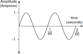
Here in North America, AC is always delivered at 60 cycles per second (hertz). One cycle would be voltage starting at zero, increasing to a maximum level in one direction, then decreasing to zero, increasing to a maximum level in the reverse direction, then returning to zero again. The unit hertz (Hz) describes the frequency of the signal and is a measure of how many complete cycles occur in 1 second. The figure below shows a 60 Hz AC signal.
60 Hz AC signal
This is the frequency equation:
f =

In the equation above, f = frequency in Hz and T = the amount of time for one cycle in seconds. You can use that equation to solve for either frequency or period when given one of them. Thus, with a frequency of 60 Hz, it can be determined that one complete cycle occurs in
 of a second, since:
T =

So, if power stations deliver AC and most electronic devices work on DC, where and how does the conversion take place? Most electric devices come with built-in AC to DC conversion systems. Later in this section, we will introduce an electric component, the diode, that makes this conversion possible.
Ground
Grounding electrical devices and residential wiring is an important safety factor. Ground represents a place of lowest potential in a circuit. Since the potential difference (voltage) is largest between any point in the circuit and the ground point, any “stray” electricity will follow this path since resistance is low here. This is important to prevent shock due to external influences such as lightning, or due to internal circuit failure where conducting wires are compromised.
In residential wiring, ground is a common connection throughout the wiring system that protects against electrical shock. All of the wiring grounds are connected to an earth ground (such as a copper rod driven into the ground or buried conduit) and this is used to guide electrical current away from panels and equipment, should an internal short circuit take place.

Important Electric and Electronic Components
The properties of a particular electrical circuit will change depending on the types of components present. In this section, several of the major ones are introduced and discussed.
Resistors
Not all components within an electrical circuit require the same voltage. There are also times when it is useful to be able to raise or limit current in a circuit in order to control certain functions (e.g., volume in a stereo). A component that can be used to limit current and/or voltage is a resistor. A resistor does what its name suggests: it creates a specific amount of resistance that generates a voltage drop when current passes through it.
As you learned previously, resistance can influence current, via Ohm’s law. An increase in R will therefore cause a decrease in the current.
Resistor Symbols
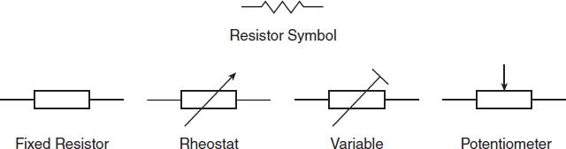
There are two major types of resistors used today: the fixed resistor and the variable resistor. Fixed resistors, as their name implies, have a fixed resistance. Variable resistors (rheostats or potentiometers), have resistances that can be changed. Potentiometers are useful in changing the voltage drop across a component in a circuit. In electronic applications, they can be used to help adjust the volume on a TV, radio, or stereo. Rheostats are useful in changing the current in a circuit and can be used as light dimmers or to control the speed of small motorized devices.
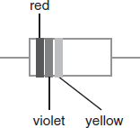
Fixed resistors use a color band system to enable us to determine their resistance in ohms. The first color gives the first number. The second color gives the second number, and the third number gives the multiplier or the number of 0s behind the numbers.
Fixed Resistor Color Bands
| Color Name | 1st digit 1st stripe |
2nd digit 2nd stripe |
Multiplier 3rd stripe |
| Black | 0 | 0 | ×1 |
| Brown | 1 | 1 | ×10 |
| Red | 2 | 2 | ×100 |
| Orange | 3 | 3 | ×1,000 |
| Yellow | 4 | 4 | ×10,000 |
| Green | 5 | 5 | ×100,000 |
| Blue | 6 | 6 | ×1,000,000 |
| Violet | 7 | 7 | - |
| Grey | 8 | 8 | - |
| White | 9 | 9 | - |
So, given a resistor with a red, violet, and yellow band, what is the value of the resistance? According to the chart, the red represents the number 2, the violet represents the number 7, and the yellow represents 4 zeros. Putting it all together, the indicated resistance is 270,000 ohms.
Given a simple series circuit with unknown resistance, how could you go about determining the value of resistance in the circuit? This can be done experimentally in one of two ways: first, by measuring resistance directly using an ohmmeter. To use an ohmmeter correctly, remove the device with unknown resistance from the circuit or disconnect the power source from the circuit (an ohmmeter has its own power source). The resistance can then be measured by attaching the ohmmeter leads across both ends of the device.
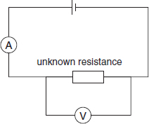
Alternatively, if no ohmmeter is available, an ammeter connected in series with the resistor and a voltmeter connected in parallel with the resistor as shown below will give I and V. Via Ohm’s law, resistance is equal to V divided by I.
Using an Ammeter and Voltmeter to Measure Resistance
Fuses and Circuit Breakers
An electric ground is one essential safety component in a circuit. It helps prevent shock by providing an alternate path for electricity to flow, away from the device. Fuses and circuit breakers are also important safety components in a circuit. When current in a circuit increases too much, wires can overheat, leading to fires.
A short circuit occurs when a load is bypassed with a conductor for some reason. Since current and resistance are inversely proportional, the flow of current will increase. This could be caused by something as simple as the insulation on the wires leading to and from the load becoming frayed and allowing the wires to come into direct contact with each other. If a short circuit occurs in part of a series circuit, the net effect is merely to remove the load that was bypassed as a result of the short circuit. If, however, the short circuit occurs at any load in parallel circuits or bypasses all the loads in series circuits, the resistance of the circuit as a whole is reduced to near zero and a dangerous surge in current could occur. For this reason, it is a good safety precaution to protect circuits with fuses or circuit breakers.
Fuses are thin wires that melt when current exceeds a prescribed amount, thereby preventing any further electricity flow. This prevents any potential damage to the electric device. One disadvantage of using a fuse is that when it has melted, or “blown,” it has to be replaced before the circuit will work again. Fuses with different current ratings can be used depending on the device specifications.
Fuse Symbol

Circuit breakers serve the same function as fuses, but have the advantage of being able to be reused multiple times. However, they respond more slowly to increases in current than fuses do, and are more expensive to install. There are several types of circuit breakers, but the underlying principle behind their function remains the same. One class of circuit breakers consists of a bimetallic strip that bends away from its contact in a circuit when too much current is flowing. This makes a break in the circuit and prevents further current flow. Another class of circuit breakers uses an electromagnet to cause a breach in the circuit. When the current rises to a certain value, the ferrous material is sufficiently magnetized to cause the circuit to open, thereby inhibiting further current flow. Later in this chapter we will explore the relationship between electricity and magnetism.
Circuit Breaker Symbol

Capacitors
Capacitors (also known as condensers) are electrical storage units. They are constructed using two metal conducting plates with a very thin insulator (known as a dielectric) between them. Air can also serve as a dielectric.
Simple Condenser

A capacitor can store an electrical charge because the DC source creates an excess of electrons on the negative plate and a shortage of electrons on the positive plate. The electrostatic attraction between the positive and negative charges keeps the charge intact in the capacitor, even when the voltage source is removed. The capacitor will discharge itself if a conductor is connected across it, as a path is then created for electrons to flow from the negative plate to the positive plate. A capacitor will allow AC to flow across it, but will block DC. This is why DC is most useful for “charging up” a capacitor.
A capacitor’s opposition to the flow of current is known as capacitive reactance, and this is measured in ohms. Capacitive reactance is inversely proportional to the frequency of the AC signal. In other words, the higher the frequency, the less opposition there is to the flow of AC across the capacitor.
General Capacitor Symbol

Capacitance, or the ability of the capacitor to store charge, is represented by the symbol C, and its unit of measurement is the farad. A farad is sufficient capacitance to store one coulomb of electrons with an electrical potential of one volt applied.
| Question | Analysis |
| In the wiring diagram pictured, the fuse is rated for 0.1 A. When the switch is closed, what will happen to the lamp in the circuit? | Step 1: The question asks what will happen to the lamp in the circuit when the switch is closed; i.e., will it light or not? |

|
Step 2: Normally, when the switch is closed, current will flow and the lamp will come on. However, this circuit has a fuse, so its impact on the circuit needs to be considered. The fuse is rated at 0.1 A. This means that it will only allow currents to pass that are 0.1 A or less. The current flowing in the current needs to be determined. Via Ohm’s law, I =  . Based on the circuit, which is a simple series, V = 30V, and Rtot = 25 Ω + 35 Ω = 60 Ω . Thus, I =
 = 0.5 A.
 |
| Step 3: Since the current in the circuit is larger than the fuse’s 0.1 A rating, the light may come on briefly, but the fuse will blow, breaking the circuit and thus the light will go off. | |
| (A) The lamp will stay lit. (B) The fuse will blow, preventing the lamp from staying lit. (C) The fuse will stay intact, but the lamp will go off. (D) The lamp will blink continually. |
Step 4: Choose option (B). |
Now try a question on your own.
-
A fuse rated at 0.5 A blows in a circuit when the switch is closed. If the total resistance in the circuit is 100 Ω, which of the following represents the smallest the voltage could have been? - 10 V
- 25 V
- 60 V
- 120 V
Explanation
Answer choice (C) is correct. If the fuse is rated at 0.5 A, it will blow when current exceeds this amount. Via Ohm’s law, a 50 V power source in a circuit with 100 Ω resistance would create a current of 0.5 A. Therefore, any voltage above 50 V, such as 60 V, would blow the fuse. Choice (D) would lead to a blown fuse as well, but the question asks for the smallest the voltage could have been.
Semiconductors
The term semiconductor refers to an element that has four electrons in its valence shell. Since the bonds between these four electrons and the nucleus are somewhat strong, these elements are neither good conductors nor good insulators. Elements that are widely recognized as semiconductors are silicon and germanium.
In their pure form, silicon and germanium are not particularly useful. However, when impurities are added to their crystalline structure in a process called doping, a whole new world of possibilities springs forth. The crystalline structure of pure silicon is very stable. The four valence electrons in each silicon atom bond with all the valence electrons in the atoms around it, so no free electrons exist to allow current flow. This can be changed by “doping” the silicon’s crystal structure with phosphorus, arsenic, or antimony. Since these elements all have five electrons in their valence shell, they will bond themselves to the other silicon atoms, but leave one free electron that is able to migrate throughout the crystal. This changes the silicon crystal into an N-type material. This new material is still electrically neutral, but is able to conduct electricity due to the presence of free electrons.
If silicon is doped with elements that have three electrons in their valence shells (such as boron or indium), the result is a “hole” being left where an electron would normally reside in the crystalline structure. This creates repeating regions with an overall positive charge. As the free electrons move into these spaces, they create “holes” in the spots they previously occupied. With such doping, the silicon is now known as a P-type material.
Diodes
P-type and N-type materials can do little by themselves; however, when the two are joined, a diode is formed. A diode is an electrical one-way valve that results from interactions at the junction of P-type and N-type material. Current can pass easily in one direction, but is blocked in the opposite direction.
Since current can only flow in one direction, the orientation of the battery in a circuit is important. If current is able to flow, this is called forward-biased. In order for the circuit to be forward-biased, the P-type material (also known as the anode) should be connected to the battery’s positive terminal and the N-type material (also known as the cathode) should be connected to the battery’s negative terminal.
The excess of electrons at the battery’s negative terminal repels the free electrons in the N-type material and sends them toward the junction. The electrons in the N-type material then cross over the junction to fill the “holes” in the P-type material, and current flows through the diode. Reversing the diode’s connection to the battery creates a new set of conditions. The N-type material’s free electrons move away from the junction, since they are attracted to the opposite charge on the battery’s positive terminal. Since the electrons have moved away from the junction, no electron transfer takes place there and current flow stops. The diode is now in a reverse-biased condition.
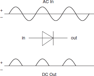
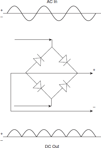
The most common application for diodes is rectification. Rectification is the conversion of AC into DC. Since a diode only allows current to flow in one direction, it will only pass either the upper or lower half of the AC waves. This is known as half-wave rectification. Four diodes can be connected in a diamond configuration to create a full-wave rectifier, which is the foundation for most DC power supplies. Diodes are also used for rectification in automotive alternators, where generated AC is converted into DC to be used in the vehicle's electrical system.
Half Wave Rectification (Single Diode)
Full Wave Rectification (4 Diodes in Diamond Formation)
Transistors
The transistor is a component that has revolutionized the construction of electronic devices such as computers, calculators and radios. A transistor is versatile, as it can be used as an electrical switch, an amplifier, or a current regulator. Since there are no moving parts in a transistor and it is made from solid silicon, it is known as a solid-state device, which makes it very reliable. It is also very compact in its design, as thousands of transistors can fit into a single integrated circuit. An integrated circuit is one that contains all necessary circuit components in one single silicon chip. Transistors are the bedrock of logic operations that a computer uses to process information.
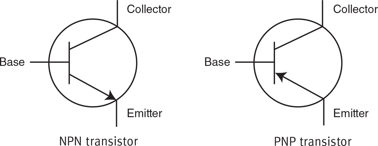
There are two types of transistors: an NPN transistor and a PNP transistor. An NPN transistor is made up of a thin piece of P-type material sandwiched between two pieces of N-type material. A PNP transistor is the opposite: two pieces of P-type material that have a piece of N-type material between them.
Inside the transistor, wires connect to the three pieces of semi-conductor material. Each piece is given a name. The middle piece is always called the base; the two outside pieces are called the collector and the emitter. The symbol for the transistor has an arrow that identifies the emitter. The direction of the arrow tells us what type of transistor it is. The key to remembering which symbol identifies which type of transistor is that the arrow always points in the direction of the N-type material.
Symbols for NPN and PNP Transistors
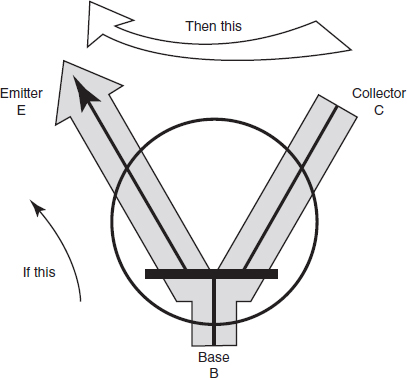
The transistor works by using a small amount of current to control a large amount of current. In the case of an NPN transistor, a positive voltage applied to the base will “turn on” the transistor and allow a relatively large current to flow from the collector to the emitter. The moment the positive voltage is removed from the base, the transistor turns off and stops the current flow.
Current Flow in an NPN Transistor
PNP transistors work opposite to NPN transistors. A PNP transistor requires a negative voltage at the base to turn it on, and the current then flows from the emitter to the collector.
Here are additional electronic component symbols that you may come across when you take the ASVAB. Some of them, including transformers, inductors, motors, and generators, will be discussed in the next section.
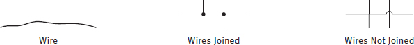
Wires and Connection Symbols
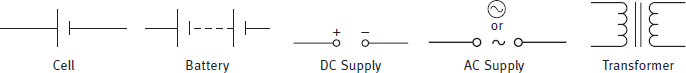
Power Supply Symbols
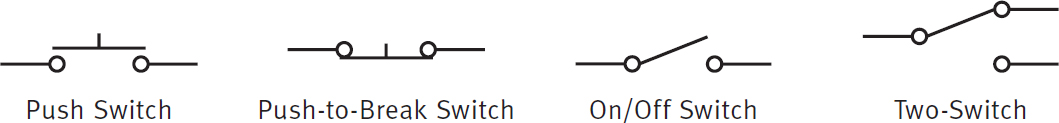
Switch Symbols
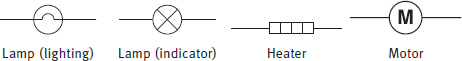
Output Device Symbols
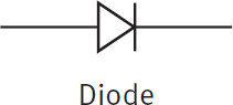
Diode Symbol
Meters and Oscilloscope Symbols

| Question | Analysis |
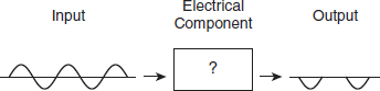
| Which of the following electrical components can be used to convert the given input into the output shown? | Step 1: The question asks what circuit component is capable of receiving the input signal and producing the output shown. |
|
Step 2: The image shows AC as the input being converted into DC as the output. |
| Step 3: A diode outputs only DC current. Any AC current that is passed through a diode will be converted to DC. Thus, only the positive or negative values of the AC signal will be output. None of the other electrical components listed converts AC into DC. | |
| (A) capacitor (B) fuse (C) resistor (D) diode |
Step 4: Choose option (D). |
Now try a question on your own.
-
A capacitor is used to store charge. When a given capacitor is “charged up” and then discharged, it will output which of the following: - direct current
- alternating current
- capacitance
- reactance
Explanation
Answer choice (A) is correct. A capacitor stores charge when a DC signal is applied across it. When the capacitor is discharged, it can only output DC.