Engine Systems
Basic Engine Theory
The type of engine used in automobiles is known as an internal combusion engine. Combustion is the rapid burning of an air-fuel mixture. Internal combustion means exactly that: fuel is burned internally and the resulting heat is used directly to power an engine.
Typical fuels used with internal combustion engines are gasoline, diesel fuel, propane, natural gas, and alcohol. Gasoline and diesel fuel are by far the most common.
Three things must be present before combustion can take place: air, fuel, and a heat source that can be used to ignite the air-fuel mixture. If any one of those three elements is missing, combustion stops and the engine will not run. Internal combustion engines convert the chemical energy in the fuel and air into heat energy, and this heat energy is then converted into mechanical energy. (See chapter 9: General Science and chapter 13: Mechanical Comprehension for more information about types of energy.)
Components
There are common components in all internal combustion engines. These components include:
- Engine block: forms the framework for the engine cylinders and reciprocating assembly.
- Piston: a cylindrically shaped object with a solid crown (top) that moves up and down in the engine’s cylinders. Hot gases produced from the combustion of the air-fuel mixture push on the piston to do the actual work.
- Cylinder: forms a guide for the piston to move in; allows the piston to move up and down as the engine completes its cycle.
- Piston rings: seal the piston to the cylinder and prevent combustion gases from leaking past. Oil rings prevent oil from the engine crankcase from making its way into the combustion chamber.
- Wrist pin: connects the piston to the connecting rod, and forms a pivot point for the small end of the connecting rod to move on.
- Connecting rod: connects the piston/wrist pin assembly to the engine’s crankshaft. The large end of the connecting rod attaches to the crankshaft on the connecting rod journal.
- Crankshaft: converts the linear (straight line) motion of the piston into rotary motion, which can then be used to power a vehicle or drive an accessory.
- Cylinder head: located above the piston, it houses the combustion chamber, the intake and exhaust valves, and the intake and exhaust ports.
- Combustion chamber: located in the cylinder head directly above the piston, it is where the actual combustion of the air-fuel mixture takes place.
- Intake valve: allows the air-fuel mixture to be drawn into the combustion chamber. When closed, it must seal the combustion chamber from the intake port.
- Exhaust valve: allows waste gases to be removed from the combustion chamber. When closed, it must seal the combustion chamber from the exhaust port.
- Camshaft: responsible for the opening and closing of the engine’s intake and exhaust valves. The camshaft turns at one-half the speed of the engine’s crankshaft.

The conversion of linear (straight line) motion into rotary motion as achieved by the piston-connecting rod-crankshaft combination is very similar to the leg of a bicycle rider. As the rider’s upper leg moves up and down (piston), her lower leg (connecting rod), the bicycle pedals, and the sprocket (crankshaft) convert that straight line motion into rotary motion that then can be used to drive the wheels of the bicycle.
Most internal combustion engines are built to utilize a four-stroke
cycle. This means that it takes four strokes of the piston to complete one cycle of events. A stroke of the piston is defined as the piston movement from the top of its travel in the cylinder (top dead center or TDC) to the bottom of its travel (bottom dead center or BDC) and back again to TDC.
The four-stroke cycle begins with the intake stroke. With the piston at TDC, the intake valve begins to open. As the piston moves downward in the cylinder, it forms a low-pressure area (or vacuum). Because the intake valve is open to the atmosphere, air is sucked into the combustion chamber due to the vacuum in the cylinder during the intake stroke. As the air is traveling through the intake system, fuel is injected into the air stream before it enters the combustion chamber. This allows the cylinder to fill with a fresh mixture of air and fuel. Once the piston reaches BDC, the intake valve is almost closed again and the engine is ready to begin the second stroke of the cycle, the compression stroke.
During the compression stroke, the piston starts moving upward in the cylinder while both of the engine’s valves are closed. With the combustion chamber then sealed, the continued upward motion of the piston toward TDC compresses the air-fuel mixture in the cylinder, as the air-fuel mixture is forced into a progressively smaller and smaller space. The air-fuel mixture in the combustion chamber becomes progressively hotter as the particles of fuel get closer together due to the compression, making the air-fuel mixture easier to ignite and ultimately increasing the power of the next stroke, the power stroke.
Just before the piston reaches TDC of the compression stroke, the spark plug fires and ignites the air-fuel mixture, starting a flame that then travels across the combustion chamber. This flame further heats the gases in the combustion chamber and the resulting rapid expansion of these gases pushes on the piston as it passes TDC and then continues downward on the third stroke of the cycle, the power stroke. During the power stroke, both the intake and exhaust valves remain closed to ensure that the pressure generated from the combustion of the air-fuel mixture is not blown out past the valves but extracted by the motion of the piston toward BDC.
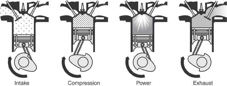
Before the piston reaches BDC, combustion of the air-fuel mixture should be completed. Just before the piston reaches BDC, the exhaust valve starts to open and the engine begins its fourth and final stroke, the exhaust stroke. The gases in the combustion chamber are now spent and must be purged from the engine before the next cycle can begin. As the piston begins its upward movement, it pushes exhaust gases past the open exhaust valve and into the engine’s exhaust system, where the exhaust gases are eventually sent out to the open atmosphere. The piston continues its travel toward TDC, and at that point will have completed one complete cycle of events. This cycle then starts over as the intake stroke begins again.
Cylinder Arrangement
Automotive engines can be built in a number of different configurations, and these can most easily be classified in terms of the engine’s cylinder arrangement, which is the position of the various cylinders relative to each other. The most common numbers of cylinders used in automobile engines are four, six, and eight, but there are also designs that utilize three, five, ten, twelve, and even sixteen cylinders.
The simplest cylinder arrangement is known as the inline design, in which all of the engine’s cylinders are lined up in a row. This is a practical design for four- and six-cylinder engines. Inline four-cylinder engines are very popular in front-wheel drive cars with transverse (sideways) mounted engines. Inline engines are most often found in small- to medium-sized vehicles. Another arrangement that has been utilized by engine designers is the horizontally opposed or flat design. This arrangement has all of the cylinders lying in a horizontal plane, with half of the cylinders facing away from the other half and the crankshaft located between them. Some refer to this design as a “boxer” engine because the pistons move back and forth like a boxer throwing punches. The one major advantage to this design is that the engine’s center of gravity is much lower, so it is easier to build a more stable, better-handling vehicle.
The last and most popular design for six- and eight-cylinder engines is the V-type engine. These engines have one crankshaft connected to pistons on both sides of the V-shaped engine. The two rows of cylinders are located 60 to 90 degrees away from each other, and each row has one cylinder head, for a total of two heads for the engine. A primary advantage of this configuration is the inherent physical balance of the engine’s moving components, resulting in a smooth-running engine. Another advantage is the decrease in height and length relative to the in-line engine. The V-type engine improves the aerodynamic flow outside the vehicle; because the engine is smaller, the front of the vehicle can be lower. If an eight-cylinder engine is needed, this configuration creates the power required while also making the engine more compact.
Camshaft Location
Another classification used to describe automotive engines is camshaft location. The camshaft is responsible for the opening and closing of the engine’s valves, and is driven by the crankshaft through a timing chain or timing belt. Some modern engines have the camshaft located in the engine block and the intake and exhaust valves located in the cylinder head. Engines built in this manner would be known as overhead valve or OHV engines because the valves are arranged above the piston and the combustion chamber. In OHV engines, a lever called a rocker arm, which is actuated by the camshaft through a pushrod, operates each valve. The OHV arrangement can be used with either V or flat configuration engines.
Engine designers often locate the camshaft above the valves and are then able to eliminate the pushrods that are necessary for the OHV configuration. The valve operating mechanism itself becomes simpler and lighter. Less mass in the valve train means that higher engine speeds can be attained. This design is known as the overhead cam or OHC. If only one overhead camshaft is used to operate the intake and exhaust valves of a cylinder for an OHC engine, that arrangement is known as single overhead cam or SOHC. In a V-type engine with two cylinder heads, there would be two camshafts, with one installed above each cylinder head.
One final step to make even higher engine speeds possible is to go to a double overhead cam or DOHC arrangement. This puts two camshafts into each cylinder head, and makes it so one cam operates the exhaust valves in that head, and the other operates all the intake valves. With this arrangement, it is possible to eliminate the rocker arms that are often used in SOHC engines and have the camshafts operate the valves directly through a follower.
Multiple-Valve Cylinder Heads
Engines may also be classified according to the number of valves used for each cylinder. The least expensive and most common arrangement is to use a two-valve cylinder head, with one intake valve and one exhaust valve per cylinder. To improve airflow through the engine and, thus, engine performance, it is possible to design a multiple (more than two) valve cylinder head. Manufacturers have designed engines that use three valves per cylinder, but now it is much more common to use a four-valve cylinder head. This arrangement has two intake valves and two exhaust valves for each cylinder. The four-valve cylinder head design has several advantages over the two- or three-valve designs. The four-valve design allows higher engine operating speeds and more complete combustion of the air-fuel mixture, which helps improve engine power and efficiency.
Firing Order
The order that the cylinders fire in is known as the firing order. A common firing order for four-cylinder engines is 1-3-4-2. This means that once the first cylinder fires, the crankshaft will make one half turn, and then the third will fire and so on. Cylinders 1 and 3 will fire on the first turn of the crankshaft, and cylinders 4 and 2 will fire on the second turn of the crankshaft. In the case of a V-8 engine with a firing order of 1-8-4-3-6-5-7-2, cylinders 1, 8, 4, and 3 will fire on the first turn of the crankshaft, and 6, 5, 7, and 2 will fire during the second turn.
Many engines have their firing order cast directly into the intake manifold for easy reference. For those that don’t, it is necessary to refer to the engine’s service information.
Diesel Engines
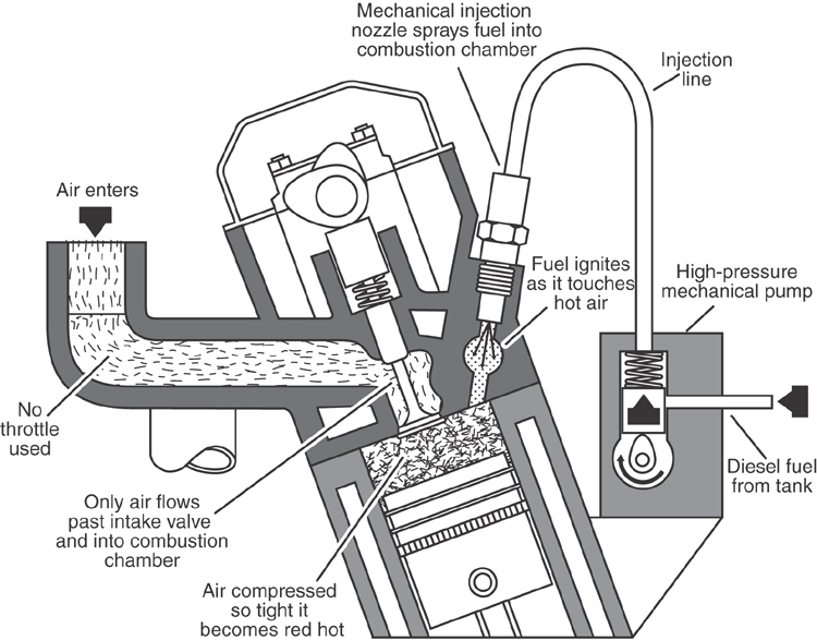
Another variation of the internal combustion engine is the diesel. Diesel engines—also known as compression ignition engines—are much simpler and more reliable than gasoline engines, mostly because they do not incorporate a spark-ignition system. Instead of using a spark to initiate combustion, diesel engines use a much higher compression ratio to generate sufficient heat of compression to ignite the air-fuel mixture. The compression ratio for a diesel engine can range anywhere from 16:1 to 22:1.
Another major difference between a diesel engine and most gasoline engines is that all diesel engines must inject their fuel directly into the combustion chamber or into a portion of the combustion chamber called the pre-combustion chamber in order for combustion to take place. The diesel engine must inject its fuel into the combustion chamber because it needs the heat of the highly compressed air in the combustion chamber to ignite the fuel, whereas all gasoline engines, including direct injected ones, rely upon the spark-ignition system to initiate combustion.
Engine Operating Conditions
Air-fuel mixture
For an engine to run efficiently, it is necessary to mix air and fuel in the correct amounts. Combustion suffers if there is too much fuel and not enough air, or if there is too much air and not enough fuel. The ideal ratio of air to fuel is known as the stoichiometric ratio, and it is the responsibility of the engine’s fuel system to maintain that balance.
Air-fuel ratio is a comparison of the mass of the air relative to the mass of the fuel that has been mixed with it. The stoichiometric air-fuel ratio for a gasoline engine is 14.7:1. This means that 14.7 pounds of air is combined with 1 pound of fuel to create an ideal air-fuel mix. When fuel is mixed with air by the fuel system, particles of fuel are atomized and directed into the air stream that is entering the engine.
Too much air and not enough fuel would be described as a lean mixture. Lean mixtures burn relatively slowly because there is greater space between the fuel molecules and it takes more time for a flame to jump from particle to particle. Lean mixtures also burn much hotter, and thus can cause serious engine damage. A typical lean air-fuel ratio might be 17:1.
In contrast, a rich air-fuel mixture has too much fuel and not enough air. Rich mixtures burn quicker because of the small distances between fuel particles, and they also burn much cooler. A rich air-fuel mixture can cause spark plug fouling and black exhaust smoke, but is certainly less threatening to an engine than lean mixtures. A typical rich air-fuel mixture might be 10:1.
Ignition timing
Another major factor in making an engine run efficiently is ignition timing. Ignition timing is the point in time during the combustion cycle that a spark is generated at the spark plug. This is described relative to the position of the engine’s crankshaft. For instance, an ignition timing of five degrees before top dead center (BTDC) would mean that the spark took place when the crankshaft was five degrees of rotation before top dead center.
The spark is most often timed so it will take place before the piston reaches top dead center on the compression stroke, because it takes time for the flame to move across the combustion chamber and burn the air-fuel mixture contained within. By the time the air-fuel mixture is burnt, the piston is on its way down again and is ready to make an effective power stroke. Regardless of how fast the engine is turning, it will take approximately the same amount of time for the flame to travel across the combustion chamber. This means that for higher engine speeds, the flame must be started earlier in order to generate the most effective downward push on the piston. This is known as advancing the timing. An example of an advanced timing would be 25 degrees BTDC. In this case, the spark takes place when the crankshaft is 25 degrees of rotation before top dead center.
In contrast, retarding the timing means that the spark is adjusted to take place later in the combustion cycle. Certain engine operating conditions might call for a retarded timing as part of normal engine operation. Ignition timing that is unnecessarily retarded, however, will have an adverse effect on engine performance.
Combustion
Gasoline engine combustion is the rapid, thorough burning of a compressed air-fuel mixture, initiated by a spark from the engine’s ignition system. It is a flame that starts at the spark plug and then moves rapidly across the combustion chamber, heating the gases and building pressure in an even, controlled manner.
Normal combustion does not involve an explosion, and it is always initiated by an electric arc at the spark plug. If combustion is started by something other than an electric arc at the spark plug, this is an abnormal condition known as pre-ignition. Pre-ignition takes place when the air-fuel mixture is ignited prematurely (before the time the spark plug would normally fire), typically by a hot spot in the combustion chamber, such as a glowing spark plug electrode or a hot piece of carbon.
Detonation is when an air-fuel mixture explodes, rather than burns. It can often take place when an engine’s air-fuel mixture is lean. This is because lean mixtures burn very slowly, and as the flame moves across the combustion chamber, the unburned gases become heated due to the advancing flame and the increasing compression in the cylinder. If the temperature of these unburned gases rises sufficiently, they will “auto ignite” and the flame front from this explosion will collide with the original flame front. The pressure spike from this abnormal combustion results in a brutal shock to the engine assembly, and can be heard as a “knock.” Severe engine damage can result from unchecked detonation.
Cooling System
There are two major types of cooling systems in modern automotive engines. The first type is air-cooling, where air is circulated over cooling fins on the outside of the engine to remove excess heat. The second type is water-cooling. A water-cooled engine uses a liquid coolant to pick up excess heat and then rejects that heat through a radiator. In order to ensure optimized emissions and efficiency, cylinder temperatures need to quickly reach operating temperature and remain consistent throughout a wide range of ambient temperatures. Therefore, virtually all newly designed automotive engines use liquid cooling, due to its greater flexibility in coolant circuit design, its heat transfer ability, and its high heat capacity.
Coolant
The most critical component of the cooling system is the coolant itself. Engine coolant is normally made up of a 50/50 mix of antifreeze and water. Frozen coolant can lead to serious engine damage (even a possible cracked block and/or cylinder head), so it is important that the coolant be freeze-protected. The most common type of antifreeze is ethylene glycol. A 50/50 mix of ethylene glycol and water will not freeze until its temperature reaches -34° Fahrenheit. This same 50/50 mix will also raise the boiling point of the coolant, which is important in hot weather, because it makes the coolant that much more efficient at transferring heat.
Components
The major components of a water-cooling system include:
- Water pump: responsible for moving coolant through the cooling system in order to transfer and control heat.
- Water jacket: hollow sections in the engine block and cylinder head that allow coolant to be transferred through them. These are the areas that the coolant must absorb heat from.
- Thermostat: controls engine temperature by allowing coolant to flow into the radiator when the coolant temperature rises above a certain level.
- Bypass tube: allows coolant to flow back into the water pump from the cylinder head when the thermostat is closed.
- Radiator hoses: flexible hoses that allow hot coolant to flow between the engine and the vehicle’s radiator.
- Radiator: responsible for transferring heat from the coolant to the outside air.
- Radiator cap: responsible for maintaining pressure in the system, and allowing coolant to transfer between the coolant reservoir and the radiator.
- Coolant recovery bottle: forms a reservoir for coolant to flow in and out of the cooling system as the engine increases and decreases in temperature.
Operation
Coolant is circulated through the engine by a belt- or timing-chain-driven water pump. The engine crankshaft drives the belt, so the water pump actually uses engine power to operate it. The water pump takes coolant in and pushes it into the engine block. The coolant then makes its way upward into the cylinder head, and then returns to the inlet of the water pump through the bypass tube. As long as the thermostat is closed (engine is below operating temperature), the coolant will continue to circulate in this manner.
When the thermostat opens, hot coolant moves past the thermostat into the upper radiator hose, and then the coolant enters the radiator itself. One of the methods used to raise the boiling point of the water has already been mentioned: using coolants made up of a 50/50 mix of ethylene glycol and water. The other method that can be utilized is raising the pressure in the cooling system. The radiator cap is responsible for this, and most are designed to maintain anywhere from 9 to 16 pounds per square inch (psi) of pressure in the cooling system. For every 1 psi of pressure that is placed on the cooling system, the boiling point of the coolant is raised approximately 3°F. A 15-psi radiator cap would then raise the boiling point of the coolant to between 212°F and 260°F.
Radiator caps incorporate two separate valves: a pressure valve and a vacuum valve. As the engine warms up, the coolant in the cooling system will tend to expand. This expansion will raise the pressure in the cooling system, but when the pressure reaches the radiator cap’s rating, the pressure valve in the radiator cap will lift and allow some coolant to flow from the radiator into the coolant recovery bottle. This flow will continue as the cooling system pressure exceeds the rating of the radiator cap. The coolant level in the recovery bottle will rise until the engine reaches operating temperature.
When the engine is shut down and begins to cool, the coolant will contract and create a low-pressure area inside the cooling system. If left unchecked, this low-pressure area would cause the radiator hoses to collapse and have an adverse effect on the cooling system at engine startup.
Maintenance
Cooling systems require maintenance in order to keep them operating at peak efficiency. Again, the coolant itself is absolutely critical and making sure to have it replaced every two to three years is a good maintenance practice. The strength of the coolant should be kept at a 50/50 mix of antifreeze and water. This will ensure that the coolant has sufficient freeze protection and corrosion resistance.
It is also important to check that the belt driving the water pump is in good condition, and that there are no leaks in the system. Hoses and the radiator should also be inspected for visible signs of damage or wear. Most often, a leak will be external and can be observed as it drips from hose connections or faulty cooling system components.

Lubrication System
Another system critical to engine operation is the lubrication system. Without lubrication, the internal parts of the engine would very quickly develop enough friction to stop (seize) the engine completely. The lubrication system is responsible for the following functions:
- Lubricates: it puts an oil film between moving parts to reduce friction and smooth engine operation.
- Cools: it puts motor oil in contact with hot engine parts (such as the underside of the piston) and transfers heat to the oil pan, or the engine oil cooler if applicable.
- Seals: motor oil acts as a sealer between the piston, the piston rings, and the engine cylinder walls. This helps seal combustion gases in the combustion chamber and makes the engine run more efficiently.
- Cleans: additives in the motor oil cause contaminants to be suspended in the oil, so they can be filtered out by the engine’s oil filter.
- Quiets: motor oil damps engine noise and makes the engine run more quietly.
Engine oil
Engine oil is a major component of the lubrication system. The engine oil is the lubricant to the moving parts of the engine. The oil must be carefully engineered to provide peak performance under the toughest engine operating conditions, so choosing and using high quality engine oil is extremely important for the life of an engine. Engine oil is made up of two main components: base oil and an additive package.
One of the most important properties of engine oil is viscosity. Viscosity is resistance to flow, and is expressed as a number that is directly proportional to the thickness of the oil. The Society of Automotive Engineers (or SAE) is responsible for developing the standards concerning engine oil viscosity. Oil with a viscosity rating of SAE 5 would have a relatively low viscosity (low resistance to flow), whereas SAE 50 oil would have a high viscosity.
Another important engine oil rating system is the API quality rating. API is the American Petroleum Institute, and it is responsible for setting standards for engine oil quality. For a gasoline engine, this rating would have a prefix of “S,” and then the next letter would identify the specific quality standard that the engine oil meets. The first gasoline engine oils produced had a quality rating of SA, but greater demands on engine oils led to ratings that currently exist at the SN, SM, SL and SJ levels. Today’s engines would not last very long if they were operated with an SA motor oil.
Engine oil with a “C” prefix for its quality rating would be suited for diesel engine use (e.g., a CJ-4, CI-4 plus, CI-4, and CH-4 rating). Engine oil that had both an “S” and a “C” rating would be suited for either gasoline or diesel engine use. An example of this would be engine oil with a rating of SJ/CD.
Components
The primary components of the lubrication system are as follows:
- Oil pan: forms the reservoir for the engine oil at the bottom of the engine.
- Oil pickup tube and screen: immersed in engine oil, this filters out large solids and directs oil into the oil pump.
- Oil pump: responsible for pumping the oil through the engine oil galleries. It is normally driven by the engine’s crankshaft.
- Pressure relief valve: prevents excessive pressure from building in the lubrication system.
- Oil filter: filters oil from the oil pump before it is sent to the various parts of the engine.
- Oil galleries: passages or “drillings” in the engine assembly that transport oil to critical components.
Operation
There are two main designs for lubrication systems: dry sump and wet sump lubrication. The dry sump system is very complex and typically only used on racing vehicles and, therefore, is rarely encountered. Virtually all mass-produced commercial and automotive engines use the wet sump lubrication system design. In the wet sump system design, the engine’s oil reservoir is located at the bottom of the engine in the oil pan. All oil used in the engine drains to the oil pan due to gravity. There, it has an opportunity to cool. The oil pump draws oil from the oil pan into its inlet through the pickup tube and screen. The engine oil moves through the oil pump, and then is transferred under pressure to the engine’s oil filter. The oil filter removes particulates from the oil, and sends the clean oil on to the main oil galleries.
When the engine is cold, the oil has a higher resistance to flow and thus requires a good deal more energy to pump it through the system. This also causes the engine’s oil pressure to rise. If the oil pressure rises above the pressure relief valve’s setting, the relief valve will open and allow some of the oil to drain back into the oil pan before it is pumped into the oil filter. This prevents engine oil pressure from rising to the point where it can damage components such as the oil filter, bearings, and engine seals.
The most critical area in the engine in terms of lubrication requirements is the engine’s reciprocating assembly. The pistons, connecting rods, and crankshaft all require oil to lower friction and to remove heat. The largest oil galleries in the engine are used to move oil to these areas, and galleries are drilled directly through the crankshaft to provide oil under pressure to the connecting rod bearings. Oil that leaks off the connecting rod bearings is thrown onto the cylinder walls, where it helps lubricate and cool the pistons.
Other oil galleries take oil from the main oil gallery and direct it to the engine’s valve train. This is where the camshaft, lifters, push rods, rocker arms, and valve stems get their lubrication. Other parts that may receive lubrication from this oil would be the camshaft drive, or timing chain, and associated gear drives for the oil pump, ignition distributor, etc.
Oil that has circulated through the engine eventually drains back into the oil pan. The oil pan is located at the bottom of the engine and thus sits low in the engine compartment, where cooler air typically resides. This cool outside air helps absorbs heat from the oil pan and helps cool the engine oil. For heavy-duty or hot-weather operation, a liquid-to-air heat exchanger (similar to the radiator in the cooling system) can be used to further cool the engine oil. Once cooled, the oil is ready to be picked up by the oil pump and circulated back into the lubrication system.
Maintenance
The key to lubrication system maintenance is to change the engine oil and filter on a regular basis, and to use top-quality engine oil and filters. This is the cheapest and most effective maintenance that can be performed to minimize wear on the engine.
Questions on the ASVAB may ask you to recall or interpret how the various systems of a vehicle operate. Let’s take a look at a sample question from the area of engine systems, which encompasses engine theory, the cooling system, and the lubrication system.
| Question | Analysis |
|
An internal combustion engine converts chemical energy of a fuel into energy to power a vehicle. |
Step 1: This question asks about the conversion of energy in an internal combustion engine. Step 2: The answer relates to Engine Theory. Otherwise, there isn’t much to simplify here. Step 3: Recall that an internal combustion engine converts chemical energy of a fuel into heat energy by burning the fuel and then converts the heat energy into mechanical energy that is used to produce useful work. |
|
Step 4: The correct answer is (B). Answer choice (A) is incorrect because electrical energy is used to release the chemical energy but is not the result of the release of the energy. Choice (C) is incorrect because work is the result of the mechanical energy produced by the engine. And (D) is incorrect because even though sonic energy (sound) is produced in the energy conversion process, sonic energy is not the source of the engine’s power. |
Now try a question on your own.
-
Engine coolant is normally made of a 50/50 mixture of - water and soap solution
- salt and alcohol
- water and ethylene glycol
- antifreeze and saltwater
Explanation
Engine coolant is composed of 50% water and 50% ethylene glycol (also known as antifreeze). The correct answer is (C). You would never want to introduce a corrosive material like salt into an automotive engine coolant; therefore, choices (B) and (D) are incorrect. Answer choice (A) is incorrect because water with a small amount of soap solution added as a “wetting agent” could function as an engine coolant, but not in a mixture of 50/50. Soap does not increase the temperature performance of the coolant as needed in automotive applications.