Chapter 1
Traditional Welding Processes 1
1.1. Introduction
To avoid any misunderstandings, the definitions of the terms which appear in this text are those proposed in the document entitled “Terms and definitions used in welding and related techniques” published by the “Publications of Autogeneous Welding and the International Council of the French Language” [COL 96].
It has been specified in the preface to this book that welding makes it possible to reconstitute metallic continuity between the components to be assembled. This reconstitution involves the re-establishment of the interatomic metal bonding forces which requires at the same time a connection of the nodes of the crystal lattices and the absence of any foreign body likely to constitute a screen.
This chapter will successively cover the physical conditions necessary to create the metallic bond and the industrial processes which make it possible to establish this bond.
1.2. Conditions to create metallic bonding
Creating the metal bond consists, theoretically, of bringing the surfaces to be linked closer so that the surface atoms are at a distance of the order of the internodal distances of their own crystalline system.
This operation, which would assume at the beginning that surfaces are chemically clean and in a specular state of polish, is not practically feasible.
To mitigate this industrial impossibility, the surfaces to be joined will have to be activated with a view to eliminating the foreign bodies and elements likely to obstruct the creation of the bond.
1.2.1. Activation of surfaces
The most effective surface activation is fusion which can simultaneously ensure their cleaning. The metallic bond is created by solidification. Different procedures can be employed:
a) the two parts to be assembled undergo a surface fusion and thus contribute to the formation of a molten metal pool (possibly with the addition of a filler) which solidifies without mechanical action;
b) the two parts to be assembled undergo a surface fusion but an external mechanical action expels the molten metal and creates the assembly by placing the surfaces in contact at the solidus temperature;
c) the two parts to be assembled undergo a localized fusion and take part in the formation of a captive molten metal core which during its solidification is compacted by the action of an external effort of compression.
The activation of surfaces can also be obtained by heating without fusion. In general it is then supplemented by a mechanical action which enables, moreover, cleaning and improvement in contact of the surfaces to be assembled. It is possible to distinguish between:
a) the case where the heating and the cleaning of surfaces to be assembled are simultaneously carried out by mechanical friction (which implies the assembly of axisymmetric parts) and is followed, after stopping the latter, by a crushing (“forging”) by axial compression; and
b) the case where the heating is carried out by external heating and the close contact is ensured by an effort perpendicular to the joint plane.
Finally, activation can result from a mechanical action without total heating of the parts to be assembled. This mechanical action causes a plasticization of the outer layer of each surface and generates a very localized heating which finally allows the establishment of the metallic bond. This process simultaneously requires a relative displacement of the surfaces to be assembled, parallel to the mating plane, coupled with a compressive force perpendicular to this same plane. It is necessary to carry out a careful surface preparation and/or to make sure that relative displacements of the latter cause the rejection of the products which pollute them.
1.2.2. Elimination of obstacles to bond creation
Obstacles to the creation of the metallic bond can be of various kinds:
– geometrical surface irregularities,
– pollution of the surface (oxides, grease, moisture, etc.),
– chemical elements brought in by the surrounding air.
Surface irregularities are likely to disrupt the creation of metallic bonds in all the cases where there is not surface fusion of the parts to be assembled. It will then be necessary to carry out a surface preparation by mechanical means (grinding, machining, etc.).
All pollution of surfaces to be assembled will have to be eliminated by mechanical action (sanding, grinding) or by chemical means (solvents, scouring, drying, etc.).
It is necessary to neutralize the possible effects of chemical elements brought in by the surrounding air. Welding operations generally being carried out in atmospheric conditions, it is especially oxygen, nitrogen and hydrogen (carried in the air’s humidity) which can be harmful.
Oxygen can react with the elements volatilized by the arc and in this way contribute to the creation of welding fumes. Furthermore, it can especially dissolve in the molten metal and, during solidification, contribute to the formation of:
– metallic oxides which constitute inclusions in solidified metal;
– porosities in the molten metal due to the drop in solubility which accompanies cooling and solidification. This formation of porosities can be aggravated by a reaction developing with an element contained in the metal and leading to the formation of a gas compound (for example, formation and release of CO during steel welding without protection against the atmosphere).
Protection against oxygen in the air can be ensured by the interposition of a neutral gas, a molten slag or by fixing in the form of oxides by the addition of oxygen hungry elements (silicon especially). In the vicinity of the molten metal, the surface of the parent metal raised to a high temperature can also react with oxygen and be covered with oxides, which is a further justification for using protective means, including at the back of the weld.
Nitrogen can dissolve in the molten metal and contribute to:
– either the formation of porosities in the molten metal due to the drop in solubility which accompanies cooling and solidification;
– or the formation of metal nitrides which, according to the conditions in which they appear, constitute inclusions or precipitates more or less hardening and weakening in nature;
– or for the part which remains in solid solution, a process of weakening by ageing.
Protection against nitrogen can be ensured by interposing a neutral gas or a molten slag.
Hydrogen dissolves in the molten metal and its concentration can reach high levels, even reaching saturation if precautions are not taken to limit its presence. Hydrogen, the solubility of which decreases when the temperature drops, can then contribute to the formation:
– of porosities during solidification;
– of cracks, in a solid state, when, oversaturated, it gathers in the form of gas molecules on the structural defects of a not very ductile metal.
Protection against hydrogen primarily consists of limiting its introduction into the molten metal by lowering the atomic or ionic hydrogen content of the plasma arc. To do this it is necessary to minimize the water content of the surrounding air (no welding in a damp atmosphere), to interpose a gas low in hydrogen between the surrounding air and the arc, to eliminate compounds supplying water (hydroxides, condensation, greases, basic non-dried coatings, fluxes, etc.) and other sources of hydrogen (cellulose or rutile coatings and grease).
1.2.3. How can we classify the various welding processes?
At this stage we are led to adopt a system of grading the welding processes according to the modes of action and means of protection against the atmosphere (see Table 1.1).
Table 1.1. Classing the welding processes according to modes of action and means of protection against the atmosphere
| Activation | Complementary action | Protection |
| fusion | none | imperative |
| compression | not essential | |
| heating | compression | possible |
| friction | compression | none |
Actually, the various welding processes are above all classified according to more practical criteria, which are:
– the energy source applied: flame, electric arc, plasma, Joule effect, spark, induction, friction, explosion, etc.;
– the means of protecting the hot metal: gas or slag.
1.3. Industrial welding processes
Industrial welding processes are set out here according to the criteria defined above, namely:
– processes utilizing the fusion without mechanical action;
– processes utilizing the fusion combined with mechanical action;
– processes utilizing heating without fusion but with a mechanical action;
– processes utilizing a mechanical action without heating.
A classification akin to industrial practices will be presented at the end of this chapter.
1.3.1. Processes using local fusion of the parts without mechanical action
For welding processes operating without voluntary mechanical action, the local fusion of the parts to be assembled can be described by distinguishing the mode of heating used and the means of protecting the molten metal against the chemical action of the surrounding air. Thus, it is possible to list:
– flame or gas welding;
– plasma welding;
– arc welding;
– vertical electroslag welding;
– aluminothermic welding.
It should be noted that, in all these processes, the molten metal weld pool is contained in a crucible formed by the shape of the parts to be assembled adjacent in the mating plane (sometimes the complete closure of the “crucible” is ensured by specific tools, e.g. slat, slides, mold). In this way a non-molten section of the parts, in the vicinity of the molten metal, is brought up to temperatures, according to its distance from the latter, between the temperature of the solidus of the metal and the initial temperature of the parts. The fraction of this volume (nearest to the molten metal), of which the structure and therefore the properties change because of this heating, is called the heat affected zone (HAZ).
1.3.1.1. Flame welding
The fusion of the parent metals and the filler is obtained by heating with a blowtorch (Figure 1.1) which enables us, by combustion of a gas (acetylene generally, hydrogen, propane) with a comburent (which is generally oxygen), to have an effective flame (of a fuel rating, with acetylene, about 100 to 300 W/cm2 on a spot of heating [RYK 74], the diameter of which is about 5 to 10 cm).
This flame comprises two zones, each with a specific role:
– a cone at the immediate exit of the blowtorch nozzle whose surface constitutes the site of primary combustion (this, if acetylene is used, releases hydrogen and carbon monoxide). At the tip of the cone the temperature is very high (using acetylene, it exceeds 3,000°C) and the atmosphere is reducing;
– a plume where combustion is completed. According to the adjustment of the consumption ratio, namely the ratio r = volume of oxygen to volume of acetylene, this plume can be oxidizing, neutral or reducing (and thus carburizing for steels). In welding a neutral flame is used corresponding to 1 ≤ r ≤ 1.2. The adjustment of blowtorch power is made by regulating the flow of acetylene which is governed by the nozzle diameter. Four nozzle sizes exist which give acetylene flows ranging from 10 by 63 l/h to 1,000 by 4,000 l/h. The flow of oxygen is regulated accordingly. This choice of acetylene flow takes account of the metal being welded, its thickness, the type of joint and the position of welding.
It is possible to add a filler metal which is generally the same composition as the metal being welded and comes in the form of rods (from 1.6 to 5 mm in diameter).
Thus, the blowtorch, from the temperatures reached, allows the fusion of metals and, by its atmosphere, ensures the molten metal is protected against any chemical reaction with gases in the surrounding air.
However, with metals that are very sensitive to oxidation (aluminum, stainless steel, copper alloys) it is necessary to use a flux (spread out over the edges requiring welding or incorporated with the rod) to eliminate oxides formed on the surface.
1.3.1.2. Plasma welding
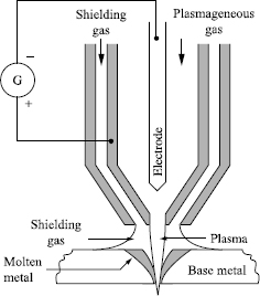
Fusion is carried out by heating using a plasma jet. This plasma is generated by the passage of a known plasma-producing gas (argon, with the possible addition of hydrogen or helium) in an electric arc created in the annular space formed between a coaxial nozzle and a refractory electrode (Figure 1.2). Generally, in DC, the refractory electrode is negative to avoid its destruction by the bombardment of electrons. The recombination in the jet of ionized species in the arc releases great energy and as a result generates a very significant rise in temperature which exceeds 10,000°C. The specific power can vary from 500 to 10,000 W/cm2 on a heating spot [RYK 74] whose diameter varies from a few millimeters to a few centimeters). A peripheral tube ensures the distribution of an inert gas (generally argon or argon mixture + hydrogen) for the protection of the molten metal. This procedure, called a non-transferred arc or blown arc, is reserved for the assembly of relatively thin components.
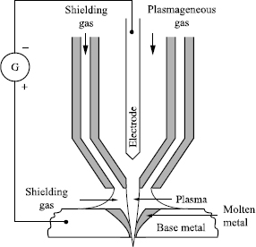
The transfer of heat and therefore thermal efficiency is improved by striking the arc between the refractory electrode and the parts to be assembled. The arc is then maintained by a pilot arc which is created between the nozzle and the refractory electrode (Figure 1.3). The name given is plasma transferred arc welding. It is the procedure most commonly used in welding. It makes the assembly of thicker products possible (albeit with a variable limit depending on the nature of the base metal, but in the order of a centimeter), often by using the keyhole procedure; the plasma jet crosses the joint by pushing the weld pool backwards where solidification occurs (the faces to be welded can thus be straight edged). In this way complete penetration is ensured and regularized. The use of a support at the back of the weld is generally not necessary because the molten zone is quite narrow (although this does not obviate the need for gas protection at the back). However, this process is not suitable for carrying out a filler pass. It is generally employed in flat welding and sometimes in horizontal/vertical welding. A filler can be introduced in the form of wire. To increase the rate of deposit, it can be beneficial to use the hot-wire technique. However, the filler can also be introduced in the form of powder into the shielding gas jet (thus around the plasma jet).
The synchronized generation of electric power pulses in the arc and in the plasma-producing gas flow makes it possible to weld in a vertical position. Such a procedure requires computerized control of all the parameters.
1.3.1.3. Arc welding
The contribution of heat used to form the molten weld pool is assured here by an electric arc operating in DC or AC. The specific power can vary here from 103 to 105 W/cm2 on a heating spot [RYK 74] whose diameter varies from a few millimeters to a few centimeters.
It must be possible for the arc to be generated easily and then remain stable. To facilitate its generation (which will allow us to avoid resorting to a too high starting voltage compared to the arc’s voltage in permanent mode) as well as to stabilize it, we have recourse to easily ionizable chemical elements which are introduced into the plasma arc. These elements can come from the fusible and volatile compounds included in the solid products which will form the slag or from gases applied to protect the molten metal. In addition, the power source must be adapted so that:
– its non-load voltage is high enough to allow arc generation,
– its normal operating voltage makes it possible to achieve arc lengths compatible with the technology employed,
– its voltage in the event of the arc’s extinction is sufficient to allow the arc to be restored.
The choice of polarity, in either AC or DC, must take account of the different phenomena which occur at the cathode and the anode. Indeed, electron emission takes place at the cathode and all the more so if the cathode is heated to a high temperature. However, if its heating is partially due to the direct Joule effect and the bombardment by the positive ions, it is above all due to the contribution of heat coming from the Joule effect which occurs in the cathode’s transition zone. This last point explains why the required current depends on the diameter of the cathode; the greater it is, the higher the current must be to maintain the cathode at a sufficient temperature.
Electrons bombard the anode and thus cause significant heating, increased further by the Joule effect in the anode’s transition zone.
If the arc uses DC, the choice of polarity depends especially on the process and the metal being welded, given that the anodic zone is heated more than the cathodic zone. The AC current supply makes it possible to alternate the phenomena at the two ends of the arc.
When the filler comes from a consumable electrode, the transfer of this metal in the arc can be achieved in three different ways according to the electric mode of the arc. At high currents, the transfer takes place by pulverization, i.e. in the form of small droplets forcibly projected by the electric field towards the weld pool.
At moderate currents the transfer takes place in the form of large droplets which, with little force applied to them, follow irregular trajectories before falling in the molten metal or, possibly in the form of projections to one side — which is generally a sign of a bad adjustment of the welding parameters. At the lowest currents the transfer takes place by short-circuit. The magnetodynamic effect is insufficient (the current is too low) to detach the droplet from the surface of the electrode; the droplet grows bigger to the point that it comes into contact with the molten metal. The short-circuit then generates a current surge which detaches the droplet, which is incorporated in the molten metal.
The products that ensure the protection of the molten metal can, according to the process, be:
– fusible compounds which form a slag floating on top (and are likely to react chemically with it to refine its composition);
– often inert gases (argon, helium or mixtures sometimes with the addition of hydrogen) with, sometimes, the addition of carbon dioxide (whose decomposition in the arc will give protective carbon monoxide and oxygen which will be fixed by elements introduced with the filler products).
In this context, many processes have been developed that can be classified according to the conditions in which the arc is struck (between the two parts to be assembled or these components and an electrode) and that can also be distinguished according to the conditions in which the welding products are applied.
a) The arc is struck between the two parts to be assembled
Arc welding with pressure created with a magnetic field
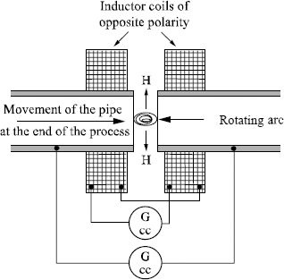
The arc is struck and moves between surfaces to be joined under the effect of a permanent magnetic field judiciously directed and controlled. After surface fusion, the parts to be joined are forced together (there is thus the formation of a seam). An alternative to this process is applied to tubular structures (Figure 1.4) using two coils which surround the tube and create two antagonistic magnetic fields. The resulting field is radial; it thus causes the rotation of the arc in the mating plane. This is rotating arc welding.
Arc welding of studs
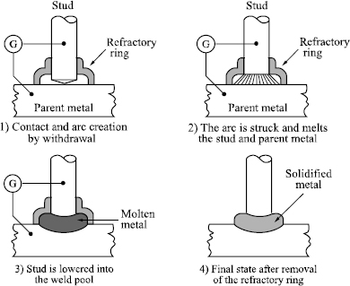
The arc is formed between the end of the stud and the target zone of the support. After fusion of the stud end and creation of a molten pool on the surface of the support where the stud is to be fixed, the stud is plunged in the molten metal and maintained in position until solidification is complete. The power supply and stud displacement (contact, withdrawal for striking the arc, maintenance then lowering — Figure 1.5) are controlled automatically. The protection of the molten metal is generally ensured by the positioning of a refractory containment ring which ensures also the “molding” of the molten metal during its solidification. The power source comes from DC or capacitor discharge; the current intensity of the arc is adjusted according to the diameter of the stud.
b) The arc is struck between a fusible electrode and the components to be assembled
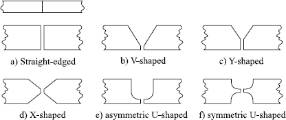
Generally, this procedure allows, with each operation, the deposit of a certain quantity of molten metal, a quantity which varies with the type of process and energy brought into play. It can prove insufficient to form a sufficient seam section between thick components; it is then necessary to carry out several operations i.e. several passes. Such a situation often requires an edge preparation to be performed, a preparation which ensures proper weld creation (access for the electrode, type of assembly, position, penetration, possible prevention of deformations, etc.). These preparations have shapes and dimensions which vary especially according to the nature of the base metal and the process employed. The principal varieties are:
– straight edged (Figure 1.6a) for assemblies of limited thickness, possibly with spacing between the edges (distance increasing with the thickness). It may be necessary to carry out a pass on the reverse to ensure penetration but it is also possible to use a support at the back;
– V-shaped chamfer (Figure 1.6b) or Y-shaped (Figure 1.6c) with heel and possible edge spacing. This type of preparation is not employed for thick components because it gives rise to considerable distortion;
– X-shaped (Figure 1.6d) with heel and possibly edge spacing. This type of preparation requires access to both sides but limits distortion;
– asymmetric U-shaped (Figure 1.6e) or, better symmetric (Figure 1.6f) if there is access to both sides (with heel and possibly edge spacing). This preparation makes it possible to reduce the quantity of molten metal necessary.
Sometimes particular preparations such as half-V shaped, half-U shaped (known also as J), K-shaped, etc. are used.
The processes which will be described are known as “semi-automatic” if the electrode or the torch is handled by the welder and “automatic” if the latter is positioned and guided by automated devices.
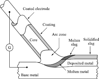
Coated electrode arc welding
The electrode consists of a metallic core (whose diameter varies from 1 to 10 mm and whose length can be up to 450 mm) which serves as the electrical conductor and supplies the filler metal, as well as an adhesive coating made up of products which contribute to the formation of a protective slag and others that volatilize in the arc plasma to stabilize it and, possibly, of metal particles which help form the molten weld pool (Figure 1.7).
This coating can commonly be:
– cellulosic: this creates little slag but its combustion releases CO2 and contributes to the enrichment of the molten metal caused by dissolved hydrogen;
– rutile: the basic component is titanium oxide; it contributes to the desulphurization of the molten metal; the binding agents used release hydrogen;
– basic (electrodes used in steel welding): the basic component is calcium carbonate; it releases little hydrogen but it is hygroscopic and so requires that the electrodes be correctly baked (300°C approximately) then protected (by maintaining them at around 100°C for example) before use.
Rutilo-basic mixed coatings (better desulfurization) or rutilo-cellulose (good penetration) are also proposed as well as coatings containing metal powders to increase the quantity of metal added (high-output electrodes) or to introduce alloying elements.
Core fusion slightly precedes that of the coating; it forms a crater which directs the transfer of the filler towards the molten metal. This transfer takes place in the form of large droplets (cellulosic or basic coatings) or by pulverization (rutile coatings).
In many cases, the arc can be DC in origin (the polarity is then selected according to the nature of the base metal, the coating and the welding position) but it is sometimes possible to use an AC current (in particular for steel welding). The intensity of the current is selected according to the diameter of the electrode; it is generally recommended by the manufacturer.
Welding is in practice possible in all positions, each one requiring particular adjustments and appropriate preparation.
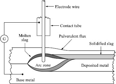
Arc welding with powdered flux
The electrode is a solid wire (approximately 2 to 10 mm in diameter) whose supply is guaranteed by an automatic device through a torch equipped with a contact tube ensuring the power supply. Upstream of the torch (compared to the direction of the welding process) a nozzle in which the arc will be struck distributes the powdered flux, part of which will constitute the protective slag, whereas the rest, covering the weld area with a layer of non-molten flux which slows down cooling, will be recovered later on. The arc is not visible, so consequently this imposes a precise piloting of the torch displacement.
This process (Figure 1.8) makes it possible to weld with high currents and a high output. However, in general, dilution is significant, about 2/3 and it increases with the welding current.
The arc is struck using DC when the welding intensity does not exceed 1,000 A; the polarity can be direct (the wire is negative) if deep penetration is required or inverse (the wire is positive) if, on the contrary, a high welding speed and a reduction in dilution is desired. With elevated currents it is sometimes easier to use AC, which makes it possible to decrease the effects of magnetic arc blow.
The Joule effect along the length of wire electrode, between the contact tube and the arc, heats the filler metal (all the more depending on length and current) and facilitates its fusion, thus increasing the quantity of filler metal in the weld pool.
Fluxes used are mixtures of mineral compounds (generally silicon manganese or silico-alumino-calcic compounds) delivered in the form of calibrated pellets. The two principal manufacturing processes give them different properties:
– so-called molten fluxes are manufactured from minerals by fusion, molded and then crushed; they thus have a vitreous and/or crystallized structure and can be porous;
– so-called agglomerated fluxes are manufactured starting from natural mineral products agglomerated or sintered (with a binder). These fluxes can adsorb or absorb water and so it is necessary to take precautions to avoid any addition of hydrogen.
In general, the manufacturers of welding products combine flux and filler metal. Each combination often makes it possible to confer their own specific properties on the molten metal.
This welding process, due to the method of flux application, enables only flat welding (and possibly at an angle with a special support). It allows straight edged butt welding with edge spacing up to significant thicknesses (depending on the base metal) but to weld very thick components it requires a preparation which account for the possibility of making a pass(es) on the reverse side:
– no access: V-shaped preparation with heel, spacing and support at the back or tulip-shaped preparation or U-shaped with heel;
– access: X-shaped with heel and spacing or K-shaped preparation with heel.
Furthermore, welding can be accelerated by associating two (or more) welding heads each with its own power supply; the electrodes are generally placed in tandem at a distance of about 25 to 35 mm.
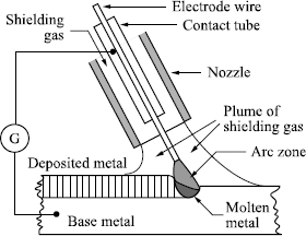
Gas shielded arc welding with a solid fusible wire
The electrode is a solid wire (from approximately 0.5 to 2.4 mm in diameter) whose supply is ensured by an automatic device through a torch equipped with a contact tube ensuring the connection to the power supply.
This torch comprises an annular gas delivery which will ensure the protection of the molten metal. This gas can be of two types (Figure 1.9). It can be inert and the process is then known as MIG (metal inert gas) welding. It can be argon (pure or mixed with helium) which ensures good arc stability and gives a good penetration, or helium mixed with argon; the proportion of argon must be high enough to preserve arc stability. It can be active and the process is then known as MAG (metal active gas) welding. In this case it contains oxygen and, more often, CO2 mixed with neutral gases (argon mainly). The presence of oxygen (whether supplied or coming from the break up of CO2) brings a certain number of advantages: the arc is more stable, the weld pool more fluid, the transfer by pulverization can be established over a broader range of power supply conditions, the chamfers are filled better and voids less likely. However, the risk of loss of elements transported in the arc leads to the introduction of elements likely to combine with oxygen into the wire electrode.
The power is generally supplied in DC and in inverse polarity (positive wire electrode) in order to increase the speed of wire fusion and to stabilize the mode of transfer, in the arc, of the molten metal. Two modes are mainly used:
– the transfer by axial pulverization for the welding of thick products but limited to butt and flat angle welding or gutter welding;
– the transfer by short-circuit which involves little energy and allows welding of thin products and all types of in situ welding.
Certain modern equipment makes it possible to superimpose pulses over the basic current in order to cause the detachment of the drops at fixed frequency and thus to stabilize their size. It then becomes possible to control their transfer and to regulate their flow whatever the welding current. The term used is pulsed welding.
Assemblies are made with all the preparation types already evoked but taking account of the need to allow sufficient access for the torch. This access can be facilitated by lengthening the wire electrode between the contact tube and the arc, with a resultant increase in the quantity of metal deposited in consequence of the heating by Joule effect in this length of wire and, generally, reduction in penetration. Welding can be carried out in all positions after adaptation of operational parameters.
Cored wire arc welding
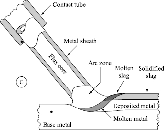
This process (Figure 1.10) is derived from gas shielded solid wire arc welding by a simple replacement of the solid wire with a flux cored wire (diameter from 1 to 4 mm). A cored wire consists of a tubular metal envelope filled with a powder (flux) whose composition and role are comparable with those of the coating on a coated electrode. According to the manufacturing process of cored wire, this can be closed (by drawing of a hollow cylindrical wire filled with flux) or formed by pleating or crimping and thus more or less sealed (but it can again comprise two parallel fillings containing flux and a metal filler powder). As the fluxes are hygroscopic and the metal sheath more or less sealed, it is necessary to take the same precautions for use as for coated electrodes. However, cored wires without slag (and thus containing metal powders) enable us, with an effective gas protection, to appreciably increase the welding speed and the quantity of metal added.
As in MIG or MAG welding, the supply of the wire is guaranteed by an automatic device through a torch equipped with a contact tube ensuring the power connection. This torch makes an annular gas supply possible, which will ensure protection of the molten metal. This gas is generally reactive (CO2, possibly mixed with argon).
The filled wire being more rigid than solid wire makes it possible to further increase the length of the wire electrode between the contact tube and the arc and thus to facilitate access (it is necessary to avoid over lengthening this distance so as not to separate the molten metal too much from the shielding gas).
Assemblies are made with all the types of preparation already evoked by taking account of the improved accessibility given by the increased length of the wire electrode between the contact tube and the arc. This makes it possible to reduce the chamfer openings. In addition, the good penetration makes it possible to increase the height of the heels and to decrease the spacing between surfaces to be assembled. Welding is generally carried out on the horizontal and sometimes in other positions, in which case, a small diameter cored wire is used.
Cored wires are also offered for welding without a shielding gas. Protection is then assured by both the slag (of which the limited quantity is not sufficient to ensure total protection) and by a dense atmosphere generated by specific products introduced into the flux. In addition, the metal sheath of the filled wire contains elements likely to decrease the harmful effects of an incomplete protection (deoxidizers and denitrifying agents). Finally the welding parameters are adjusted to reduce the length of the arc. These cored wires make it possible to decrease the size of the welding torch, to facilitate access and thus limit the preparation required.
c) The arc is struck between a refractory electrode and the components to be assembled
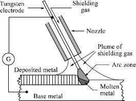
The non-consumable electrode consists of a tungsten tip (Figure 1.11) held in a torch equipped with an annular gas delivery which will ensure the protection of molten metal. This gas is neutral: argon (sometimes with the addition of hydrogen — up to approximately 30%) or helium. Argon gives good arc stability but helium ensures better thermal efficiency and thus deeper penetration. These considerations mean that argon-helium mixtures (about 80% Ar and 20% He) are often used. This process is most commonly called TIG (tungsten inert gas) welding. It can be necessary, depending on the base metal, to set up a gas protection on the reverse side using a gas which can be either identical or different from that supplying the torch (nitrogen-hydrogen).
The electrode (0.5 to 10 mm in diameter) can be pure tungsten or tungsten with an addition of zirconium oxide (0.3-0.5%) or thorium (1-2%). These additions make it possible to increase the electrode emission capacity and thus to improve arc stability and help arc initiation. They also increase the electrode performance and thus the acceptable maximum current. The shape of the electrode point is a significant parameter of TIG welding. The electrode is often pointed in DC mode, and hemispherical in AC.
The power supply is generally DC with direct polarity (negative electrode) so as not to subject the electrode to electron bombardment. In this way the energy impact is concentrated on the parts to be assembled and at the same time a narrow bead and good penetration are achieved. The arc can also be established by AC (with a suitable power source) when an electronic bombardment is desired to clean the parts to be assembled. Arc initiation is often assisted using a pilot arc.
A filler can be introduced directly into the molten metal pool either in the form of rods or in the form of wire using a mechanized reel, allowing, if necessary, the pre-heating of the wire to improve the deposit rate.
Assemblies are produced using all the preparation types already evoked above taking account on the one hand of the limitation of the volume of molten metal and, on the other hand, of the need for taking particular care (cleanliness, dimensional accuracy especially with regard to the spacing of the parts — it can be useful to set up a support on the reverse side). Welding can be carried out in all positions after adaptation of the operational parameters.
An easier use of the TIG process and an increase in penetration can be obtained by applying a fine layer of a reactive flux to the surface of the edges to be assembled.
The composition of this flux (often formed of oxides and/or halides) must be selected according to the nature of the base metal.
Vertical electroslag welding
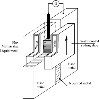
This process consists of forming a molten metal bath in a vertical parallelepipedal mold formed by the two sections to be assembled and two water-cooled copper shoes applied to the surface of the two parts (Figure 1.12). The continuous supply of molten metal due to the filler fusion (consumable wire electrode and possibly fusible wire guide) and the progressive solidification of the molten metal little by little consolidate the two parts. Above the molten weld pool, a bath of slag (thickness 40 to 60 mm) ensures its protection. The permanent heating is due to the Joule effect which develops partly in the electrode but especially in this molten mineral pool. Welding progresses vertically upwards. It begins with the striking of an arc between the wire electrode and an appendage which closes the bottom of the mold and on which a welding flux is deposited (which will form the slag).
When the volume of molten metal is sufficient, the quantity of flux necessary to constitute the slag layer is introduced; the arc then ceases. It is generally preferable to set up, in the edge prolongation to be assembled, two blocks of the same composition as the base metal and of the same thickness. The weld’s end point will be after the molten metal has reached the level of these blocks so that the shrinkage at the end of solidification does not affect the weld per se (any surplus deposit thus created will be removed later on). According to the dimensions of the parts to be assembled, the side shoes can be moved upwards to follow the progression of welding.
The heat affected zone is wide, because of the very significant heat generation. According to the thickness of the parts to be assembled several wire electrodes can be used simultaneously. To carry out welds of considerable height, a fusible wire guide plunged in the slag and melting simultaneously the wire electrode(s) can be employed; this fusible wire guide contributes to the molten metal weld pool. The term then employed is vertical electroslag welding with fusible wire guide. The procedure generally makes use of AC.
This process allows butt welding and welding at an angle (by using adapted shoes) of work pieces whose thickness is generally not less than 40 mm.
Aluminothermic welding
In this process the welding is carried out by running a metal in fusion (filler) into a mold built around the two faces of the parts to be assembled, placed face to face, at a specified distance. These two faces are often pre-heated with a flame via holes provided in the mold. The molten metal is created on the spot by aluminothermy, i.e. exothermic reaction between oxides (of the metal filler) and powdered aluminum. This operation is carried out in a crucible placed at the top of the mold. As the molten filler is run in, the surface of the parts to be assembled melts, preceding solidification of the assembly. The protection of the molten metal is ensured by the slag which is formed during the aluminothermic reaction. Afterwards, it is necessary to remove the mold and grind the assembled parts, so as to eliminate any excess deposits.
1.3.2. Processes using local fusion of components with mechanical action
The contribution of heat used to form the molten weld pool is assured here by the Joule effect of a high intensity alternating current which crosses the mating plane. It is the contact resistance between the two surfaces of the parts to be assembled which makes it possible to concentrate fusion in this plane.
Several processes have been developed that we can classify according to the fate reserved for the molten metal; containment or expulsion. All require rather heavy and specific equipment.
1.3.2.1. Resistance welding with containment of the molten metal
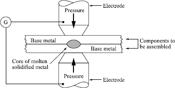
This process combines the Joule effect and a mechanical pressure applied to the outside of the assembly, perpendicular to it and right where the molten metal zone is. This force has the aim of ensuring a good electrical contact between the parts to be assembled, thereby confining the molten metal in the zone where it is formed and applying pressure to it after its solidification in order to improve its compactness by avoiding shrinkage (an operation known as spot forging). Generally the electrodes carrying the current apply this effort. These considerations show that they are overlapping assemblies of products of limited thickness. The containment of the molten metal within the joint avoids any contact with the air; the problem of its protection thus does not arise.
The effectiveness of this process is related to the localization of the zone heated by the Joule effect, which depends on the electric contact resistance between the parts; precautions must be taken so that, on the one hand, other resistances in series in the electric circuit are much lower and that, on the other hand, there is no possibility of the welding current being diverted to one or more parallel circuits.
The piloting of the welding current as well as that of the compression force are handled by automatisms which can:
– apply pressure before the passage of the current, to bring the two components into close contact and to ensure the electrical contact,
– adjust the current intensity and limit its duration (in general, of a few periods to a few tens of periods i.e. durations which are calculated in tenths of a second),
– adjust the pressure during the passage of the current to prevent the surfaces separating (due to dilation) and the consequent dispersion of the molten metal,
– maintain or increase the effort to ensure the compactness of the volume of molten metal,
– if required, run a reduced current as a post-heating.
The electrodes are copper-based alloys. The addition of alloying elements (Cr, Zr, W, Cd, Co, Be, etc.) confers the necessary mechanical performance without overly affecting their electric conductivity and thermal conductivity. Their contact surface to be welded must be clean and uniform in shape.
In this way resistance spot welding, projection and roller seam welding can be carried out.
Resistance spot welding
In this process current supply and load application are carried out by cylindrical electrodes with tips in the shape of a truncated cone cooled by internal water circulation. Their contact surface is generally flat or slightly convex. They are installed on fixed machines or mobile tools; it is always desirable that the step-down current transformer is placed as close as possible to the welding zone.
The volume of molten metal has an ovoid form and is called a spot weld. The welding is discontinuous and a seal cannot be guaranteed. The final load application generally causes an indentation on the two faces of the joint; it is possible to avoid on one of the two faces by replacing the electrode with a copper plate through which the welding current passes.
It is possible, in certain cases, to carry out two spot welds simultaneously by coupling two transformers (double spot in series with push-pull assembly), or with only one transformer (provided that it is possible to control the currents).
Resistance projection welding
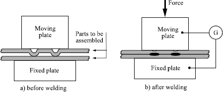
In this welding process (Figure 1.14), the passage of the current is localized by raised areas called projections created on one or both of the assembly surfaces. These bosses are stamped on thin flat sheets and machined in other cases. The supply of the current and the load application are applied, generally, using plates; during the heating and fusion the bosses collapse and the mobile plate must react very quickly to ensure the close contact of the parts to be assembled. If the power supply is powerful, it is possible and economic to weld several bosses simultaneously. The wear of the plates and deformation of the components are minimal. The geometry of the projections must be precisely controlled.
Roller resistance welding
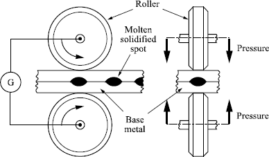
In roller resistance welding (Figure 1.15), the electrodes are replaced by copper or copper alloy discs called rollers. These rollers are driven to ensure the progression of the components. Of course, they carry the electric current and apply the necessary load.
The electric current, in general, is modulated as in spot welding but in a repetitive way and the welding consists of successive spots. It can be:
– discontinuous if the successive spots do not overlap. It is possible to stop the roller rotation at each spot and to carry out spot compression, and the result is identical to that of spot welding. It is also possible to work uninterrupted but in this case without forging (the effort applied remains constant),
– continuous if the various points overlap, i.e. if the formation of each point involves the partial remelting of the preceding spot. The welding then forms a perfect seal.
It is possible, in roller welding, to carry out the seam welding of thin sheets using the force applied during welding; the extra thickness is then eradicated. It is necessary, to achieve this, that the overlap does not exceed one and a half times the thickness and that the sheets to be assembled are gripped very tightly.
1.3.2.2. Resistance welding with expulsion of the molten metal
These processes combine the Joule effect with applied mechanical pressure, after heating, from outside of the assembly and perpendicular to it, over all its surface. This force has the aim of creating the bond by keeping in close contact the surfaces heated to their solidus temperature. A weld metal bulge is formed at the ends of the assembly, which must then be eliminated. As the heated zone is confined, the problem of its protection is not relevant. Within this framework two rather different processes are employed.
Upset resistance butt welding
The effort is applied in two stages: first of all for the cold joining of the parts in order to allow the passage of the current through the surfaces to be assembled, then, after passage of the current, to ensure the weld bond; an excess, or weld bead, is formed which must be eliminated. The Joule effect is limited to the contact zone between the two parts and the heating must bring them up to the forging temperature.
This process is a large-scale consumer of energy and requires careful preparation of the faces to be assembled (which must be parallel and perpendicular to the effort applied). Therefore, flash welding is sometimes preferred.
An alternative used for the longitudinal closure welding of cold formed sections utilizes high frequency (HF) induction heating. The HF current is applied by two contacts rubbing on the weld edges, above the intended weld, where they are still separate.
Due to the skin effect, the current works its way along the edges to the contact point, where it generates heat (eventually to the point of fusion) and allows the bond to be formed with the pressure of two rollers. This process can be implemented each time it is possible to create an induced current which crosses the mating plane.
Flash welding
The parts are brought closer only after the current is supplied so that the current is first of all only transmitted by contact points created by the imperfections of the opposing surfaces; at these points the current density is very high. From the beginning of fusion the liquid part is expelled in the form of small incandescent particles; this is the flash. Gradually this flashing takes over the whole mating surface. Once this result is achieved the contact pressure is increased to drive out the molten metal and the impurities which it contains and to ensure the connection; the current is simultaneously shut off. An excess weld bead is formed in this last phase; it will have to be eliminated. A pre-heating of large section parts limits the electric output and the force required. It also decreases the loss of matter during flashing but increases the volume of the bead and the duration of the operation.
This process does not require a careful preparation of the faces to be assembled; flashing alone is sufficient. In general, it is not necessary to protect the molten zone from oxidation in as much as the force is applied straight after the flashing.
This process allows end to end welding of variously shaped components and sections (from just a few mm2 to more than 1,000 cm2).
1.3.3. Processes using heating without fusion but with mechanical action
Heating can be achieved from an external source (resistance or induction) or by mechanical action (friction). The applied forces must be carefully controlled. These processes thus require very specific equipment.
Diffusion welding
Diffusion welding is a process of solid state coalescence in which the parts to be assembled, put in contact under suitable pressure, are brought up to and maintained at a sufficiently high temperature (but very slightly lower than the melting point) to allow atom diffusion through the mating plane. This, helped by localized plastic deformations, can ensure metal continuity. The pressure can be:
– perpendicular to the mating plane: it is then often recommended that to avoid macroscopic deformation, it does not exceed the limits of elasticity of the metal at the diffusion temperature,
– isostatic: the pressure is in this case not limited and the resorption of porosities is greatly improved.
The surfaces to be assembled must have undergone a careful preparation by fine polishing (to ensure the closest contact possible) and cleaning (to eliminate any pollution likely to obstruct the diffusion). It is possible to insert one or more non-fusible leaves (strip iron or deposit) between them.
Precautions must be taken to avoid any hot reaction of these surfaces with the atmosphere (vacuum welding or in a neutral atmosphere). For a given preparation, the quality of the assembly depends on the pressure, the temperature and the duration of maintenance at temperature.
It has been shown [LEF 92] that fast localized heating by induction under a judiciously modulated axial load (so as to be at any temperature equal to the corresponding limit of elasticity) makes it possible to achieve an assembly following a maintenance at a temperature whose duration varies, depending on its level, between 1 and 60 seconds. The heating conditions make it possible, in addition, to carry out a heat treatment within the framework of the thermal welding cycle. This procedure is applicable to many metals.
Friction welding
Friction welding is a process of butt welding under pressure which involves a rotation of the parts against each other (maximum circumferential speed of about 150 m/min) and the application of an axial load in order to generate, by friction, heat at the interface (only one part is put in rotation; it must be circular and its diameter, if solid, can vary from a few mm to 150 mm approximately). When the required temperature is reached, rotation is stopped and the axial load is simultaneously increased to ensure welding by forging.
The rotating part is turned by a servo motor or a flywheel. In the first case movement stops due to disengaging and braking, in the second the stop follows the exhaustion of the flywheel’s kinetic energy (which was spun before the operation at a sufficient speed to ensure the required heating).
The joint does not contain molten metal and this fact has two principal consequences:
– the joint has good mechanical properties;
– it is possible to weld different metals (iron and aluminum for example).
An excess bead is formed at the periphery of the joint; it must be eliminated. The cleaning of the surfaces to be assembled is ensured by friction; this process thus requires neither careful preparation of the surfaces nor their protection in the course of the welding operation.
If none of the two parts to be assembled can be rotated, it is possible to intercalate an adapter which can be rotated.
A process which can be compared to friction welding is currently proposed under the name friction stir welding. It employs a non-consumable rotary tool, of suitable shape, which penetrates the mating plane; friction causes significant heating which lowers the elastic limit of the base metal. A significant plasticization develops and the tool movement (at a speed which would be approximately that used in arc welding) causes a flow of matter running from the front to the back of the tool, where it ensures the bond between the two parts to be assembled. The properties of such an assembly are interesting.
Forge welding
In this process the parts to be assembled are heated to a sufficient temperature then hammered to cause the connection by plastic deformation at the interface. Between the two faces to be assembled, it is necessary to employ a cleaning product (equivalent to a flux) which ensures the elimination of oxides by ejection during hammering.
1.3.4. Processes using mechanical action without heating
Ultrasonic welding
This is a process of lap welding under contact pressure, during which ultrasonic vibrations (20 to 100 kHz) are briefly applied so that the two faces to be assembled are set into motion against each other. A negligible volume of metal, on both sides of the mating plane, is thus raised (by friction) to the recrystallization temperature and ensures the bond as a result.
The ultrasonic energy required is that much greater the thicker (generally not exceeding 2 mm) and harder the components are. It is possible to weld different metals.
Explosive welding
This welding process is used to produce assemblies by covering or cladding. The covering or cladding metal is violently projected against the base metal by the progressive detonation of an explosive layer distributed on its outside face. The shock wave, as it spreads, causes the ejection, in front of the contact zone, of a jet of metal which perfectly cleans the faces to be assembled and enables the creation of the bond. However, for this to occur, it is necessary that, before welding, a gap is established between the two faces which have been chemically cleaned beforehand. Their surface (from a few cm2 to several m2) can be flat, cylindrical — tubes — or crooked. It is possible to assemble different metals.
1.4. Bibliography
[COL 96] COLLECTIF, Termes et définitions utilisés en soudage et techniques connexes, Publications de la Soudure Autogène, 1996.
[LEF 92] LEFRANCOIS P., KERGOAT M., CRIQUI B., HOURCADE M., “L’assemblage de l’acier en quelques secondes grâce au soudage-diffusion-dynamique à l’état solide: cas du 27CD4 soudé à 1050°C”, Mémoires scientifiques de la Revue de Métallurgie, January 1992.
[RYK 74] RYKALINE N.N., “Les sources d’énergie utilisées en soudagé”, Soudage et techniques connexes, December 1974.
1 Chapter written by Guy MURRY and Dominique KAPLAN.

