Chapter 2
High Density Energy Beam Welding Processes: Electron Beam and Laser Beam 1
Welding processes using high density energy beams result from the application, in the second half of the 20th century, of work conducted by physicists in the fields of x-rays and vacuum techniques for the process of electron beam welding and optronics for laser beam welding. The possibility of concentrating these beams on points having a very small surface area led engineers to use this property to melt materials to achieve welds or cuts.
Compared to traditional arc welding processes, these two processes are characterized by a very high energy density at the impact point on the work piece. Rykaline [RYK 74] gave a representation comparing for several processes the heat flows at the center of the heat sources and the diameters of these sources. We can observe that the energy density measured at the focal point of a laser beam or an electron beam is 10,000 times higher than that reached in an oxy-fuel flame (see Figure 2.1).
2.1. Welding properties using high density energy beams
These result from the dimension of the focal points (lower than a millimeter in general) used at the level of the parts to be welded. These properties are as follows:
– single pass welding;
– welding without filler material when there is no gap between the parts to be joined;
– welding of thin parts (tenths of millimeters) by heat conduction;
– welding of very thick parts (tenths of millimeters) by the formation of a vapor capillary. In this last case, two modes of welding are observed:
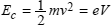
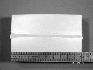
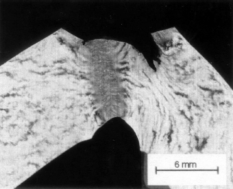
- complete penetration weld using a keyhole when the electron or photon beam passes through the whole thickness of the workpiece (see Figure 2.2),
- partial penetration weld when the beam only melts part of the thickness of the workpiece (see Figure 2.2);
– very narrow welds (molten zone and heat affected zone) because of the very high energy density;
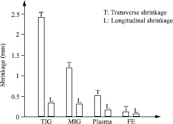
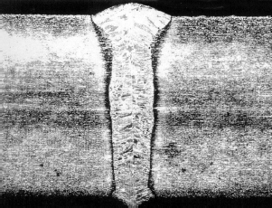
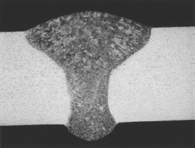
– welds inducing very low distortion, which makes these two processes a precision mechanical solution, since it thus becomes possible to weld machined parts or parts not requiring deformation correction after welding. Figure 2.3 illustrates the deformation (transverse and longitudinal shrinkage) obtained during the welding of a 15 mm thick sheet of martensitic steel by GTAW, plasma arc, GMAW and electron beam;
– welds with gas protection (laser) or under vacuum (electron beam), which ensures a good protection against the oxidation of the molten zones and heat affected zones and makes it possible to weld materials sensitive to this phenomenon such as titanium and zirconium.


Figure 2.3. Comparison of the transverse and longitudinal shrinkage of a butt welded martensitic stainless steel assembly (Institut de Soudure document)
2.2. Laser beam welding
2.2.1. History
Einstein surely did not suspect the technological revolution to which his stimulated emission theory, established in 1917, would give rise. The technological adventure could only really start in 1954 when Professor Townes and his team developed the first stimulated emission amplifier and oscillator, which they baptized “MASER” (Microwave Amplifier by Stimulated Emission of Radiation). This discovery was followed by many others. In 1958, Schawlow and Townes demonstrated the theoretical possibility of producing coherent light by stimulated emission of radiation. The first laser source was a ruby laser produced by Maiman in 1960. It was very quickly followed by the development of the first gas laser by Javan (helium-neon laser). Many mediums were then studied and used for the manufacture of lasers: doped crystals, semiconductors, ionized gases, molecular gases, liquids, dyes.
Laser is currently experiencing an extraordinary development. It is used in many spheres of activity.
2.2.2. Principle
Laser is an acronym formed by the initial letters of Light Amplification by Stimulated Emission of Radiation.
An atom can pass from a fundamental state E1 to excited state E2 by the absorption of a certain energy quantity (hυ). This energy contribution can be mechanical or kinetic in origin. This atom will revert to its fundamental state by the restitution of this energy quantity, it is “the spontaneous emission” expressed by the following relation:

where h is Planck’s constant and υ the emerging photon frequency.
These randomly emitted photons produce a light known as “incoherent”. There is no relationship of phase, direction and polarization between all these photons.
If an incident photon causes a return to the fundamental state of the excited atom, there is “stimulated emission”. The two emerging photons are in phase, they have the same direction and same polarization as the incident photon: there is light amplification by stimulated emission of radiation.
The excitation of the medium is called “pumping”. It allows the population inversion between excited and non-excited atoms. Pumping requires an external energy source which can be assured by electrical discharge or radio frequency in the case of gas lasers, and by lamps or laser diodes in the case of solid lasers.
A laser source must thus be made up of three principal elements:
– an active medium made up of particles (atoms, ions, molecules),
– an energy source to carry out the pumping of the medium and thus to obtain the population inversion,
– a resonator cavity made up of two mirrors ensuring photon oscillation. If one of the mirrors is partially reflective, it will allow some of the photons to escape which will constitute the coherent light beam.
The laser beam thus obtained will have certain characteristics of divergence, polarization and energy distribution which will define the quality of the laser beam.
2.2.3. Various laser types
2.2.3.1. CO2 laser sources
Gas laser sources are most commonly used for working on materials. The active medium consists of a gas mixture containing helium (50%), nitrogen (40%) and CO2 (10%). Pumping is carried out by electrical discharge or more often by radio frequency. The excited nitrogen molecules transfer their excitation to the molecules of CO2. The radiation wavelength of 10.6 µm thus obtained does not allow the transport of the beam by optical fiber. Only transport by mirrors, a less flexible system, is possible. In spite of the possibility of pulsing the beam, welding mainly uses CO2 in a continuous mode of operation. The electrical efficiency of such laser sources is lower than 10%.
The search for increasingly powerful laser sources with a better beam quality and better efficiency have led to the development of various technologies. Those differ in the direction of gas circulation, the type of excitation and the shape of the cavity. We can distinguish five.
Sealed laser sources
These consist of a discharge tube containing the gas mixture. They are limited in power (≤600 W) but deliver a very good quality beam. In the field of metallic materials, they are particularly well adapted to engraving and cutting thin sheets. However, their good beam quality also enables them to be used for the welding of thin strip iron. Advantages of such sources rest in their low cost and the possibility of installing them on mechanized systems.
Slow axial flow laser sources
These are the first CO2 laser sources to have been developed. The gas circulates slowly in the tubes in the axis of the laser beam (10 m/s). The excitation of gas is ensured by electrical discharge. These laser sources produce a very good quality beam but their power per unit of volume is limited to 0.5 W/cm3.
The maximum power of these laser sources is low (≤1,000 W). They can be used for cutting and welding thin materials.
Fast axial flow laser sources
The gas moves at high speed in the beam’s axis (≥200 m/s) using pumps or turbines in the cavity made of glass tubes. The excited gas is then cooled by heat exchangers and progressively regenerated. The excitation can be obtained by electrical discharge but the most recent sources use radio frequency. This mode of excitation has several advantages:
– more homogenous excitation,
– the electrodes placed externally suffer less and their maintenance does not require the opening of the cavity,
– greater flexibility in use.
The power obtained per unit of gas volume can reach 2 to 3 W/cm3 for an excitation by electrical discharge and from 8 to 10 W/cm3 for excitation by radio frequency. Increasingly compact laser sources are obtained by reducing the cavity shape. Sources of 20 kW are proposed in today’s industrial market.
These are the laser sources most commonly used today. They equip cutting and welding machines.
Transverse flow laser sources
The gas flow moves transversely across the axis of the laser beam thanks to one or more turbines. They do not use glass tubes. The cavity consists of a sealed metal chamber. The power per unit of gas volume is about 2 to 3 W/cm3. The maximum power reached is high (up to 45 kW). The laser beam obtained is of lower quality than for a fast axial flow laser. Such beams are mainly used for welding or surface treatments.
So called SLAB laser sources
The parallelepipedic cavity generates a rectangular beam configuration. The beam then passes into a spatial filter which makes it circular. The gas moves slowly in the cavity. The excitation of gas is carried out by radio frequency. The power available lies between 100 W and 6 kW. This technology makes it possible to obtain compact sources of a higher efficiency. Gas consumption is low and the beam obtained is of very good quality (close to Gaussian beam TEM00).
2.2.3.2. Neodymium YAG laser sources
It is a solid-state laser whose active medium is yttrium aluminum garnet monocrystal doped with neodymium ions (Nd3+). The wavelength of this laser, 1.06 µm, enables it to be transported by optical fiber. This low volume monocrystal (for example, a bar 150 mm in length and 9.52 mm diameter) is placed in a reflective cavity. The excitation of the medium is ensured by xenon lamps or laser diodes. The electrical efficiency of the laser depends on the pumping system, 1-3% for a lamp pumped system and in the order of 10% for laser diodes. The cooling of the system is ensured by water circulation in the cavity.
Two modes of Nd:YAG laser operation should be noted: pulsed and continuous.
Pulsed YAG laser sources
Pulsed YAG laser sources generally consist of a pumping module that delivers an average power ranging between 300 and 500 W. These YAG lasers can reach up to 2 kW on average by adding, in series, additional amplifying modules to this pumping module. The pulsed operation mode is ensured by flash lamps which produce with each impulse an optical response of a defined frequency and pulse length. The mode of operation for these lasers is schematized in Figure 2.4.

The characteristics of a pulsed YAG laser are related to its peak power, which can reach 50 kW. The relations between the various laser parameters are as follows:
– peak power: 
– average power: Pm = E × F(W);
– pulse duration: τ(ms);
– pulse energy: E(J);
– pulse frequency: F(Hz).
High peak powers are reserved for drilling or cutting operations. For welding, the peak power must be limited and depends on the material and the thickness to be welded. They should not exceed 4 kW. The use of a high peak power will cause material spattering. For this reason, the average power of the sources intended for welding should be limited to 500 W. Sources of greater power will be used only for high pulse frequencies. The penetration depth will in any event be limited to 1.5 mm for a quality steel weld.
Continuous YAG laser sources
These were developed after pulsed YAG laser sources. The excitation of the medium is ensured by continuously lit xenon lamps. The average powers reached are higher than in the case of the pulsed YAG laser sources: 4 to 5 kW. The essential difference between the pulsed mode and the continuous mode lies in the peak power. In the case of the continuous mode, the peak power is equal to the average power.
Figure 2.5. Pumping chambers of a continuous lamp pumped rod YAG laser (4kW average beam power) (Trumpf document)

The current developments are mainly directed towards increasing the power of these sources and of the pumping system (see Figure 2.5). The power increase is obtained by the increase in the number of pumping chambers (resonators and amplifiers). In the case of a conventional laser source with cylindrical bars and lamp-pumping, the maximum number of pumping chambers currently put in series is eight. This limitation is mainly due to beam degradation. The beam quality of industrial continuous YAG lasers around 25 mm.mrad enables a laser beam of more than 4 kW to be carried in a 0.6 mm diameter optical fiber.
The development of diode-pumped rod Nd:YAG laser sources in the year 2000 has offered scope for progress (see Figure 2.6). The system of pumping by laser diodes allows a better efficiency (≥10%) and a clear improvement in beam quality (15 mm.mrad).

The development of diode-pumped rod laser sources were a stage in the technological development of YAG laser sources but they have not been used industrially. They have encountered considerable technical problems linked to the reliability of the diode laser sources used for pumping. Today they have been replaced by new types of laser sources, diode-pumped disk laser sources and fiber laser sources.
Disk laser sources
For diode-pumped disk laser sources, the active medium consists of small sized YAG disks (see Figure 2.7). Laser sources up to 8 kW power beam are available for industry today, with a very high beam quality (0.8 mm.mrad) and high degree of efficiency. As opposed to the rod systems, the disk laser has no thermal lensing. This means that the beam quality is constant across the entire power range. Further developments of more powerful laser sources are expected in the near future (16 kW). The exceptional beam quality obtained using these laser sources allows the transport of up to 8 kW beam power in a 0.2 mm diameter optical fiber.

Fiber laser sources
This new laser source has recently been developed for industrial applications. It was initially developed for the telecommunications industry in the early 1990s. Its active gain medium is an optical fiber doped with a rare element like Ytterbium. This type of laser source can produce a very high power output (over 20 kW) with a very good beam quality. The efficiency attained is around 25%.
2.2.3.3. Semiconductor laser sources (or laser diodes)
The stacking of a multitude of semiconductors makes it possible to obtain laser diode systems from a few tens of watts to several kilowatts. The wavelengths available are 0.808 and 0.940 µm. The multiple beams emerging from these stacks are treated by sophisticated optical systems in order to be combined. The poor quality of beam produced is not conducive to optimal beam focalization. The rectangular and large-sized focal point generates power densities on the workpiece lower than 105 W/cm2, which is insufficient for keyhole welding.
These characteristics make it an excellent tool for the welding of synthetic materials, brazing, surface treatment or conduction welding. The particular advantage of this technology lies in its high energy efficiency (>25%), the compactness of the sources, the low operating costs (absence of lamps or lasing gas) and the low wavelengths (better absorption by metallic materials and possible transport by optical fiber). The development of optical systems allowing for a better focusing of the laser beam is keenly awaited and will revolutionize the use of these laser sources.

2.2.4. Laser systems
2.2.4.1. Laser beam transport
The beam emitted by a laser source must be transported to the component to be welded with minimal losses. The transport and focusing systems used depend on the laser beam’s wavelength. Nd:YAG laser beams can be transported by optical fiber whereas the CO2 laser can only be transported by mirrors. In this case, the optical pathway must be confined and pressurized in order to avoid the mirror deterioration and the possible degradation of beam quality.
The optical fiber must be as small in diameter as possible. The beam quality is then essential. Pulsed YAG laser beams averaging from 400 to 500 W in power can be inserted into a fiber 400 µm in diameter, continuous YAG lasers pumped by 4 kW lamps use optical fibers 600 µm in diameter and disk laser sources pumped by laser diodes benefit from a reduction in the optical fiber diameter (an 8 kW beam using a 200 ìm diameter optical fiber). The power losses are limited to less than 10% per optical fiber.
The mirrors most commonly used for CO2 laser beam transport can be made out of bare copper, gilded copper or covered in molybdenum. Gilded copper is valued for its very low absorption properties but it is fragile and expensive. Bare copper also has low absorbance and is comparatively inexpensive, but tends to oxidize. Molybdenum covered copper is extremely resistant but its reflective properties are lower than the others. There is no precise rule for the choice of mirrors. It is however advisable to avoid using bare or gilded copper for focusing heads subjected to projections and welding fumes. The pressurized optical transport can consist of bare copper mirrors (less expensive), of gilded copper mirrors (good reflectivity) or of molybdenum covered mirrors (more resistant but more absorbent).
2.2.4.2. Focusing
The laser beam must be focused on the workpiece in order to obtain the power density necessary to weld. YAG laser beams are generally focused using glass lenses. CO2 laser beams whose power is lower than or equal to 3 kW can be focused using selenium-zinc lenses or mirrors. Higher powered CO2 laser beams are generally focused using mirrors alone. These can be bare or gilded copper, molybdenum covered copper or solid molybdenum. Gilded copper is generally avoided for the construction of optical focusing heads because of its fragility.
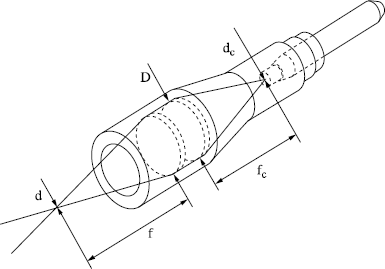
The dimensions of the focused beam depend on the beam wavelength, its quality and the focusing system used. The diameter of the focal point is related to these parameters by the following equation:

with:
– d: diameter of the focal point,
– M2: factor of beam quality,
– λ: wavelength,
– F: focusing distance of the optical system,
– D: diameter of the beam before focusing.

In the case of YAG lasers, the focal point diameter depends primarily on the optical fiber diameter, and on the collimation and focusing system (see Figure 2.11), which explains the importance of minimizing the optical fiber diameter:

Another important dimensional specification of the focal point is the field depth L. It is defined as being the zone in which the diameter of the beam increases no more than 5%. It can be expressed in the following way:

While remaining within this tolerance of ±5% of the focal point diameter, the variation in the resulting power density does not exceed 10%. We will see hereafter the importance of this criterion for the welding process.
2.2.4.3. Beam and workpiece displacement system
There exist various mechanized beam and/or workpiece displacement systems. These systems are conceived according to the type of laser source used, the dimension of the parts to be welded and economic considerations. Contrary to the market of laser beam cutting, welding machines are often dedicated to an application. In order to reduce the costs, the manufacturers propose more and more machines by catalog or machines made up of standardized sub-assemblies.

For the simplest components, machines with fixed optics are used. The components are moved under the focused beam. Only the focusing optics are moved vertically to adjust the position of the focal point or to allow the loading and the unloading of the part. For this type of simple application, the optical pathway does not justify the use of optical fibers.
For more complex trajectories, we may have to use robotized systems with several axes of motion. There are two types: Cartesian robots or polyarticulated robots. Cartesian robots are mainly used for the mirror displacement in the case of CO2 lasers. They can incorporate up to five axes of motion. These precision mechanical systems, are expensive and require a rigorous optical pathway design (see Figures 2.12 and 2.13).

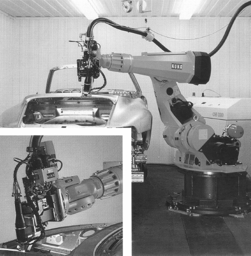
The development of high power continuous YAG laser sources and of beam transport by optical fibers has increased the use of polymorphic robots for welding operations. Their unquestionable advantage is the very competitive installation cost compared to the five axis Cartesian systems. The applications are currently mainly for the welding of automotive bodyshells (see Figure 2.14).
These robots offer less positional precision than gantry robots, but this disadvantage can be compensated by the use of real-time trajectory monitoring systems.
These robots can be equipped with a remote welding system (see Figure 2.15). This technology makes welding possible at a considerable distance from the workpiece. This remote process uses the latest high quality laser sources (disk laser and fiber laser sources).
2.2.4.4. Peripheral systems
Peripheral systems are the devices that monitor the correct functioning of the laser system (power measurement, beam analysis, etc.), to supervise the welds being made (infrared thermography, plasma analysis) and facilitate robot operation (joint monitoring systems).

Power measurement
Laser sources are equipped with an internal system of power measurement. It gives an indication of the beam power emitted by the source. This power value does not take account of possible losses along the optical pathway. External measurement systems are available to measure the beam power at the component site. These systems do not allow the power measurement during welding, so they will be complementary to internal measurement systems, which can give an indication during the welding process.
Beam analysis
In the case of laser beam welding, the focused beam constitutes the welding tool, hence the importance of understanding its characteristics perfectly. Empirical methods allow an evaluation of the position and diameter of the focusing zone. The difficulty in using these methods increases with the power of the laser beam.
Devices have been developed in order to determine laser beam characteristics in a precise way. The operating principle of these devices is based on taking away of part of the beam and analyzing it using photodiodes. On average, beams up to 20 kW with power densities 107 W/cm2 can thus be analyzed.
Weld monitoring
One of the principal advantages of laser beam welding is its high speed. This advantage can quickly become a disadvantage if a defective weld is not detected in time. This can lead to the rejection of a great quantity of parts. It is thus necessary to monitor the welds on the production line in order to detect the defects as soon as possible. Several methods are employed.
Infrared thermography — an infrared camera scans the back of the weld bead, very close to the weld pool. The anomalies noted in the temperature isotherms make it possible to highlight the formation of a welding defect. This control technique indicates the presence of an anomaly but does not give information about the quality of the weld. It can be used in addition to other monitoring techniques. This technique, which is difficult to control, is not very well suited for production line monitoring.
Plasma analysis — this method consists of analyzing the emission of plasma and the weld pool. The sampling of data is carried out at the level of the laser/material interface by optical fibers or optical components located in the optical pathway. The sensors used are photodiodes whose fields of sensitivity can be located in the ultraviolet (emission of plasma), the visible range or infrared (emission of the weld pool). An analysis of the signal makes it possible to correlate the events detected with the appearance of weld defects. These devices make it possible to detect in real-time the formation of defects and to set off an alarm at a predetermined level. Control by closed loop is at the development stage.
Seam tracking system
Seam tracking, initially developed for conventional welding, has been adapted to laser welding. The laser triangulation technique makes it possible to carry out detection of the joint position in a reliable way for an environment where normal vision is disturbed (fumes, projections, highly emissive plasma). The majority of systems use the projection of a laser line which is compared with a computerized model [BOI 98]. Visualization by CCD camera is nowadays offered as a competitive alternative to laser triangulation.
2.2.5. Implementation of laser beam welding
Laser/material interaction
The laser beam is focused on the surface of the part so as to obtain a power density in the range of 5.105 and 5.106 W/cm2. Figure 2.16 shows that a power density threshold exists for the creation of a vapor capillary or keyhole.
Figure 2.16. Penetration depth and absorption coefficient in relation to laser beam intensity; from [HER 86]

The threshold of the power density is a function of the following factors:
– the nature of the material to be welded,
– the laser beam wavelength,
– the shielding gas,
– the workpiece surface quality.
The nature of the material plays a big role in the creation of the vapor capillary. Materials such as silver, gold, copper alloys and aluminum alloys are not easily weldable by laser beam because of their low absorption coefficients.
Figure 2.17 shows that, because of their wavelengths, YAG laser beams and laser diode beams are absorbed better by metallic materials than a CO2 laser. We will see that the wavelength can be a selection criterion for the welding of materials with a low absorption coefficient.

The low absorption coefficient of a material can be compensated by a high power density. This high power density can be obtained by the use of a good quality laser beam, the choice of short focal length optics, the increase in laser power or, in the case of a YAG laser, the use of a small diameter optical fiber.
The choice of assistant gas is also paramount. A good control of the gas supply and an appropriate choice in its composition have an important impact on the welding process and weld quality.
Shielding gas
The majority of the fusion welding processes (except the electron beam) require a shielding gas at the weld surface and if necessary at the back of the weld bead. In certain cases, a shielding gas covering can be used.
We can distinguish three zones to be protected: the weld pool, the surface of the weld just after solidification while still sufficiently hot to oxidize, and the root of the weld bead. For the protection of the weld pool and vapor capillary, we can use:
– a coaxial nozzle,
– a lateral nozzle,
– a plasma blowing system.
The coaxial and lateral nozzles transport gas at atmospheric pressure and at a low flow (15 to 30 l/min according to the power of the laser beam). They allow a good protection of the weld bead without disturbing the weld pool. The coaxial nozzle has the advantage of being usable for welding in all directions, which is not the case of the lateral nozzle.
The use of a plasma jet is used in some particular cases. This consists of using a small diameter tube (≤6 mm) tilted at an angle ranging between 35 and 45° in relation to the surface of part with a high gas output. The gas jet, directed a few millimeters above the surface of the part, blows the gas plasma. This system is little used, because it does not allow a good gas protection and tends to disturb the weld pool.
The principal assistant gases used are the inert gases helium and argon or the active gas, that is, nitrogen. In the case of laser beam welding, gas protection does not only have the role of protecting the weld pool from contamination, it also takes part in the interaction between laser and material. The choice of gas thus depends on many factors:
– ionizing potential of gases,
– laser beam wavelength,
– nature of the material to be welded.
Gases subjected to a high density of power ionize more or less easily. Helium whose ionizing potential is high (24.46 eV) creates a not very intense and rather permeable plasma regardless of the laser beam’s wavelength. It can be used up to powers of 45 kW without particular problems. Argon and nitrogen, whose potential for ionization are lower (Ar: 15.68 eV and N2: 15.51 eV), create an intense plasma which hinders the interaction of beam and material. In the case of the CO2 laser beam, the use of these gases will be limited to powers ≤5 kW. From the perspective of welding performance, helium ensures the deepest weld penetration compared to nitrogen and argon and the narrowest weld beads. The addition of helium to argon makes it possible to limit the harmful influence of argon generated plasma. Commercial mixtures (helium/argon) are offered, especially for welding by laser beam. These mixtures can be used for powers up to 10 kW.
In the case of the Nd:YAG laser, the choice of gas is not so important. The first data collected indicates that the use of argon or nitrogen with a Nd:YAG laser or fiber laser is possible with powers up to 10 kW.
Argon and helium, being inert, can be used whatever the nature of the material to be welded, which is not the case with nitrogen. The latter can cause metallurgical transformations in the materials to be welded. It is not to be used for welding zirconium and titanium alloys, as it will form titanium nitrides and zirconium nitrides which will weaken the assemblies. Nitrogen can also cause an increase in the sensitivity to hot cracking of austenitic stainless steels because of its gammagene effect (it leads to the formation of austenite as well as primary austenite solidification). For these materials, its use will be subject to procedures that prevent hot cracking. However, because it is soluble in stainless steels, nitrogen could be used with some advantage to avoid the formation of porosities in the molten zone [BAR 98]. Its use for welding non-alloyed and slightly alloyed steels does not pose a particular problem if a high quality of welding is not required.
2.3. Electron beam welding
2.3.1. History [FRI 98]
The earliest applications of the electron beam result from the work completed by K.-H. Steigerwald in Germany and by J.A. Stohr at the CEA (Atomic Energy Commission) in France. For the latter, this work was justified for the welding of combustible material casings made of zirconium alloy, a material very sensitive to oxidation and for which there did not exist, at that time, a suitable welding process. The production of an electron beam required vacuum conditions which naturally gave protection against oxidation. Thus, welding was made possible and the first EB welds were obtained using a focused electron beam produced by a Guinier cathode system. A patent was thus declared in 1956 and licenses granted to companies for the construction of machines, which appeared on the market in 1960.
The first machines had low power electron beam guns (a few kilowatts), which limited the thicknesses that could be welded to approximately ten millimeters. Very quickly, the gun power that could be increased (30 kW in 1970), which made it possible to consider the welding of very thick parts (40 to 50 mm) encountered in boiler manufacturing or heavy engineering.
During the 1980s, new applications were sought, with more than 1,000 machines being built in Western Europe between 1980 and the end of the 20th century.
2.3.2. Principle
The process of EB welding uses the energy dissipated by electrons at the moment they strike the part to be welded.
The electronic beam
The electron is a particle characterized by its mass m = 9.1 × 10⁻³¹ kg and its negative electric charge e = 1.6 × 10⁻¹⁹ Coulomb. When this electron is placed in a space where an electric field E and a voltage V exists, it is subjected to a force F = eE. Under the action of this force, the electron moves with a speed v and will acquire, by ignoring the relativity effect, kinetic energy:
If we consider n/t electrons emitted per unit of time, the power transported by the electron beam will be:

with:
– V: acceleration voltage of the electrons,
– I: intensity of the beam.
Specific power
This is defined as the ratio between the power transported by the beam and the impact area of the beam on the parts to be welded. In welding, this specific power is a few tens of kW/mm−2.
In fact, all the power is not transformed at the point of impact because of losses in the electron trajectory between the emission point and the point of impact on the part.
The first losses are due to collisions with the atmospheric molecules; they are all the more significant the higher the air pressure is.
The second losses are less important in quantity; they are due to re-emission phenomena, the most important of which is x-ray emission. The energy quantity thus dissipated is low (~ 1%) but the consequences are important from the perspective of safety.
2.3.3. Equipment
Three welding techniques appear according to the pressure value P close to the workpiece:
– P > 10−5 mbar: secondary vacuum welding,
– P ~ 10−2 mbar: primary vacuum welding,
– P ~ 1,000 mbar: welding without vacuum.
The equipment used is obviously different but they all include:
– an electron beam gun with its viewing system,
– a welding chamber containing the parts to be welded and sometimes the electron gun. This enclosure also contains the displacement systems for the parts and the gun,
– a pumping unit to obtain a reduced pressure into the gun and the chamber,
– a power supply and numerically controlled command and control circuits.
The electron gun
Figure 2.18 illustrates the principles of a triode electron gun, which include:
– a cathode made of a very emissive material: tungsten, tantalum or lanthium hexaboride. This cathode is heated in vacuum conditions, either directly by an electric current (direct heated electron gun), or indirectly by a primary electron beam resulting from a heated filament (indirect heated electron gun);
– a non-magnetic Wehnelt surrounding the cathode and acting, on the one hand, on the shape of the equipotential surfaces and thus on the shape of the beam (the electrons move perpendicularly to these surfaces) and, on the other hand, on the electron acceleration where this plays the part of a grid in a triode;

– a copper anode carrying a positive charge compared to the Wehnelt creating the electric field to accelerate the electrons. This anode is bored in its center with a channel which allows the electron beam to pass through. This converges immediately at the exit of the anode then diverges under the effect of mutually repulsive electrons as they move apart;
– a magnetic focusing coil with windings in the same axis of symmetry as the gun. It reconcentrates the divergent beam and concentrates it on a small point (about a millimeter in diameter);
– a set of magnetic deflection coils enabling the beam to move in relation to its axis (side sweepings, circular movement, etc.);
– a system for accurately positioning the beam on the joint by an optical viewing system or a television camera system.
According to the electrode geometry and in particular of those of the anode and Wehnelt, the maximum current available I will be determined according to the acceleration voltage V by a characteristic of the gun called perveance p and expressed as:

The gun powers vary according to the thicknesses which need to be welded. They range from 5 to 100 kW but most of the installations are equipped with guns that have a power ranging between 10 and 30 kW. With regard to the acceleration voltages, here those lie between 45 kV and 150 or even 300 kV, depending on the technologies chosen by the manufacturers and the power required from the gun.
The welding enclosure and displacement mechanisms
The enclosure (vacuum chamber) contains the parts to be welded with their tools and their workpiece displacement. It can also contain the electron gun with its displacement system with one or more axes. Generally, this enclosure must be of a low volume compatible with that of the parts to be welded, but it should be understood that too large a volume involves a longer pumping time, which has a detrimental effect on the equipment productivity.

In addition, these enclosures must be designed to resist atmospheric pressure without any deformation and their internal sides walls must be clean in order to limit the effects of gas adsorption and thus reduce the pumping time.
The enclosure volumes used industrially vary between 0.5 m3 and more than 1,000 m3 (see Figures 2.19 and 2.20).

In order to avoid building large-scale enclosures, it is desirable to create the vacuum locally, where the weld is to be made. This solution was adopted between 1970 and 1980 for various applications, including the welding of connecting pipes on boilers or tubes on tubular exchanger plates. Although tempting a priori, this solution has effectively been abandoned, because equipment with localized vacuum chambers was very expensive due to its application to only one type of part, and it did not offer great flexibility in use.
The systems for positioning and moving the parts are tables with one or two axes or turning gears for the welding of rotating parts. These mechanical axes are controlled numerically.
Vacuum creation systems
For the machines in primary vacuum, the pumping unit consists of standard mechanical pumps (rotary vane pumps or Roots booster pumps).
For those working in secondary vacuum, one or more oil diffusion pumps or turbomolecular pumps are added.
The pumping unit’s delivery is a function of the enclosure volume to be pumped, the pumping time and degasification related to the nature and the thickness of material being welded. This last criterion is particularly important when welding very thick parts. This pumping delivery can reach levels from 2,000 to 5,000 m3.h−1 for mechanical pumps and from 10,000 to 20,000 l.s−1 for oil or turbomolecular pumps.
Non-vacuum machines or under reduced pressure [POW 00]
The first industrial non-vacuum EB welding machine was used in the USA automotive industry towards the end of the 1960s. The essential characteristic of this type of equipment lies in the absence of a vacuum chamber, which is very important for mass production, e.g. automotive components like transmission components, torque converters and exhaust systems. Counterbalancing this advantage is the disadvantage of having to use a very high acceleration voltage (150 kV) in order to obtain a sufficiently powerful beam on the work piece, in spite of passing through a gaseous atmosphere of only a few millimeters. This high voltage generates strong X-ray emissions and it is thus necessary, in order to protect the operators working on the machine, to create an enclosure ensuring containment of this radiation.
Unlike in the USA, this type of process was little used in Europe. However, since 1990, significant developments have led to new equipment which functions at atmospheric pressure or under reduced pressure (<1 mbar). There is thus a renewed interest in this technology in two fields: thin sheet welding for the automotive industry (welding of aluminum panels) and welding of thick parts such as pipes for gas pipelines and containers for storage of radioactive elements.
Implementation of EB welding
Achieving a good quality weld requires the following parameters to be monitored:
– the power transported by the beam: it is the product of the electron acceleration voltage and the beam intensity. The power will be selected according to the thickness of the parts to weld, the nature of material and its physical properties (for the same thickness, we need more power to weld copper than steel) and welding speed;
– the welding speed: this should not only be selected according to gun power but it must be determined by the metallurgical weldability of material, i.e. its ability to form a defect-free weld (with no cracks for example);
– the pressure in the enclosure: this parameter is linked to the equipment, which is designed to work either in primary vacuum or in secondary vacuum. Some machines are able to work either in primary vacuum or in secondary vacuum; in this case, the choice of the pressure will be dependent on the material to be welded and its reactivity with oxygen (zirconium alloys for example);
– focus current: this very important parameter because it determines the specific power and thus has an important effect on the geometry of the molten zone. This parameter varies according to the nature of material to be welded and its thickness. It is thus related to the acceleration voltage and the welding intensity;
– beam deflection makes it possible, by movements imparted to the beam, to carry out welds by limiting the movement of the component. It is possible for example to perform a small diameter circular weld without any movement of the workpiece or of the gun while making the beam describe a cone having for its axis that of the workpiece;
– beam vibration: depending on the signal imparted to the deflection coils, it is possible to impart sweeping movements to the beam, (transverse or parallel to the welding seam and circular or elliptic in shape). Two parameters, amplitude and frequency, are added to the signal, which have a bearing on the width of sweeping and the stirring of molten metal. This beam vibration is used at an operational level to widen the molten zone and thus to tolerate a gap between the components, to improve the quality of the weld pool when welding in position. From a metallurgical perspective, it can help reduce hot cracking observed with certain materials (nickel alloys for example) and aid degassing of the weld pool, thus limiting porosities;
– the welding position: a flat welding position (beam axis is vertical) is used for welding thicknesses from 15 to 20 mm with a complete penetration mode. This limitation is due to the loss of balance between the surface tension forces which maintain the molten metal on the edges of the capillary and gravitational force. In partial penetration mode, the maximum weldable thickness in flat position is about 130 mm for steels. Beyond these limits, it is necessary to use the horizontal/vertical welding position (beam axis is horizontal). In this case the thicknesses are dependent on the electron gun’s power. Vertical upwards welding and vertical downwards welding can also be used on steel thicknesses from 60 to 80 mm. For the overhead welding position, the maximum thickness is the same as that of the flat welding position.
2.3.4. Design and preparation of the parts
In general, welding is carried out without filler, on straight joined edges. Figure 2.21 illustrates some frequently used preparations.

These few examples show that, to profit from all the advantages offered by these processes, the choice of process will have to be made in the research department. The absence of a gap is sometimes difficult to achieve. Some gap between components can be tolerated; its value will vary with the thickness of the parts to be welded but, for thicknesses lower than 15 mm, this gap is approximately 10% of the thickness. Above this, it is necessary to use a filler in order to avoid overly thin areas. This is frequently carried out by laser beam; in EB welding, implementation is more delicate.
Because of component machining, a thorough degreasing prior to welding and an elimination of oxides present close to the joint are required to obtain a quality weld.
In EB welding, special attention must be paid to the remanent magnetism of components because of the risk of electron beam deviation and consequently of a welding defect like lack of fusion. This magnetism will thus have to be monitored before welding and the parts can possibly undergo a demagnetization operation. It is however necessary to realize that this is a delicate operation and does not always lead to the anticipated result.
In order to ensure a precise positioning of the photon or electron beam in relation to the joint, positioning and fastening assemblies are often required. These must be precise and made of non-magnetic materials in the case of EBW.
2.4. Metallurgy of high density energy beam welding
The principal features of high density energy density beam welding processes compared to conventional welding processes (arc welding) are:
– the absence of filler wire in most cases,
– high welding speeds which involve higher solidification and cooling rates,
– a narrow molten zone and heat affected zone,
– low heating and a limited deformation of the parts,
– no direct contact between the energy source and the component.
These features involve characteristics related to the behavior of the materials to be welded. In order to study these characteristics, it is advisable to distinguish, on the one hand, pulsed welding modes such as pulsed YAG laser beam welding and, on the other hand, continuous welding such EBW, CO2 laser and continuous YAG laser processes. The thermal cycles obtained during pulsed welding are shorter than those obtained in continuous mode.
In order to present the weldability problems of various metallic materials in a coherent way, we will distinguish [MUR 94]:
– operative weldability: this relates to problems encountered at the time of welding, when the behavior of the metal or alloy to be welded prevents the weld being completed;
– metallurgical weldability: during the welding process, one of the zones which constitute it (molten zone, bond area, or HAZ) can be altered because of the operation itself, to the point of questioning the performance of the assembly under the operating conditions envisaged.
Operative and metallurgical weldabilities will be presented for the main metal alloys (steels, aluminum alloys, nickel alloys, titanium alloys, zirconium alloys and copper alloys).
2.4.1. Steels
2.4.1.1. Operative weldability
Steels generally offer a good operative weldability. In addition to the advantage linked to the absence of a vacuum enclosure, the laser welding processes offer, compared to EB welding, the advantage of being insensitive to beam deviations, remanent magnetism in the case of ferritic steels or, in the case of heterogenous assemblies, the Peltier effect. Stainless steels must however be welded with gas protection, catered for by using a gas carriage.
2.4.1.2. Metallurgical weldability
Non-alloyed or low-alloyed steels
With regard to metallurgical weldability, apart from certain features of the high density energy beam processes evoked before (no contact with the parts, absence of hydrogen, lower shrinkage stresses), these welding processes significantly limit the cold cracking phenomenon.
Figure 2.22. Illustrations of CO2 laser welds in 25 CrMo4V steel (from [COL 97]). 25CrMo4V: 0.005% of sulfur, 0.015% of phosphorus (no cracking) 25CrMo4V 4: 0.031% of sulfur, 0.016% of phosphorus (cracking)

On the other hand, work completed at the Institut de Soudure [COL 97] highlighted an increase in hot cracking due to the combined effects of the high welding speed and presence of residual elements, sulfur and phosphorus in particular (see Figure 2.22).
The ranges of chemical composition recommended by the current standards do not take account of the specificities of the high density energy beam welding processes. A restriction in residual elements (sulfur, phosphorus) is essential in order to limit the risks of hot cracking.
Austenitic stainless steels
Many prediction diagrams depicting the metallurgical structure of as-welded alloys have been established and modified as welding processes have evolved. Inter alia, the Schaeffler diagrams [SCH 49], Delong team diagrams [DEL 56] or Suutala diagram [SUU 79] established for conventional welding processes are no longer applicable for welding processes involving rapid cooling. For this reason, a study carried out by the Institut de Soudure [CHE 93] looked at the influence of thermal conditions and steel composition on the liability of stainless steels to hot cracking when welded by a laser beam. It was shown that these hot cracking phenomena are not very important during continuous welding mode but become highly significant during pulsed welding.
Figure 2.23. Prediction diagram of hot cracking during pulsed YAG laser beam welding of austenitic stainless steels; from [CHE 93]

A new prediction diagram for hot cracking dependent on the sulfur, phosphorus and boron content of the alloy’s chemical composition in terms of equivalent Cr/Ni, and of the primary solidification mode (austenitic or ferritic) has been established for the pulsed YAG laser and CO2 laser beam processes (see Figure 2.23).

This diagram presents three distinct fields: two non-cracking domains and a cracking domain. The alloys, of which the Cr/Ni equivalent is higher than 1.7, are not very sensitive to hot cracking up to a high impurity content. They result from a ferritic solidification mode followed by a solid state austenitic transformation. The second non-cracking domain corresponds to alloys whose Cr/Ni equivalent is lower than 1.58 but whose impurity content is low (S + P + B ≤200 ppm). The cracking domain is defined by a Cr/Ni equivalent lower than 1.58 and an impurity content of (S + P + B) >200 ppm. Alloys whose Cr/Ni equivalent is between 1.58 and 1.70 are in a transitory zone where hot cracking depends on impurity content.
Figure 2.24. Austenitic stainless steel pulsed YAG laser bead on plates; from [CHE 93a]. X2CrNi18-09 Cr/Ni eq. = 1.75% (S + P + B) = 0.0475% (figure on left) X2CrNiMo17-12-2 Cr/Ni eq. = 1.57% (S + P + B) =0.0481% (middle) X2CrNiMo17-12-2 Cr/Ni eq. = 1.523% (S + P + B) =0.0106% (figure on right)

This work showed that external factors, such as the use of nitrogen (gammagene) as a shielding gas, can contribute significantly to the formation of cracks (see Figure 2.25).
Ferritic stainless steels
The main issues encountered during the welding of ferritic stainless steels are grain enlargement and nitride and chromium carbide precipitation which can cause intergranular corrosion. These phenomena are particularly prevalent during the use of welding processes using high linear energy. The high density energy beam welding processes, with low heating and high cooling rate, limit these phenomena and improve the welded joint’s mechanical strength in a significant way.
Figure 2.25. Comparison of beads on plates carried out with various shielding gases (from [CHE 93]). Bead on plate with helium (figure on left). Bead on plate with nitrogen (figure on right)

Martensitic stainless steels
Martensitic stainless steels can be sensitive to the cold cracking phenomenon. The factors which give rise to cold cracking are:
– high percentage of carbon (>0.3%),
– stresses caused by the welding process or unsuitable joint design,
– high cooling rates,
– the presence of hydrogen in solution.
Figure 2.26. CO2 laser beam lap weld of X2CrMoTi 18-2 ferritic stainless steel (Institut de Soudure document)

Various arrangements make it possible to limit or avoid the cold cracking of these steels:
– the use of an austenitic filler wire,
– pre-heating and post-heating,
– avoidance of hydrogen introduction.
The high density energy beam welding processes have great advantages compared with conventional processes. Having no contact with the part to be welded, they limit hydrogen contamination, and with the molten zone being very narrow, the stresses caused by shrinkage during solidification are significantly reduced. Certain steels considered unweldable by arc processes have been welded without filler wire and pre-heating.
Precipitation hardening martensitic stainless steels lose their mechanical properties after welding if they are welded in an age hardened state. It is appropriate, if the design of the parts allows it, to weld in a hyperquenched state and to carry out the ageing treatment after welding.
Austenoferritic stainless steels (duplex or super-duplex)
These steels owe their good mechanical characteristics and their good corrosion resistance to their microstructure made up of 50% of austenite and 50% of ferrite. The high cooling rate induced by welding causes an imbalance between ferrite and austenite. The high cooling rate generated by the high density energy beam welding processes involve the formation of an almost entirely ferritic structure in the molten zone. The reduction in welding speeds and/or the introduction of nitrogen as a shielding gas increases the austenite content. Unfortunately, these techniques do not suffice to obtain a duplex structure (see Figure 2.27). The high density energy beam processes will be usable only whenever the corrosion requirements are not at maximum.
Figure 2.27. CO2 laser butt welded joint of 3 mm thick austenoferritic stainless steel; X2CrNiMoN22-5-3 (Institut de Soudure document)
2.4.2. Aluminum alloys
Operative weldability
The main issues of operative weldability for aluminum alloys relate to the presence of the refractory oxide layer and their high conductivity. The oxide layer requires the surface cleaning of the parts before welding, whatever the welding process used. The laser welding of aluminum alloys is made more difficult because of their low absorption coefficient. In this case, a YAG laser has a slight advantage compared to the CO2 laser because of its lower wavelength, which allows a better radiation absorption.
Electron beam welding has advantages for the welding of these alloys because it does not have the absorption problem of laser beams, while the weldable thicknesses are high (see Figure 2.28) and the weld beads are narrow. The thermal welding cycle is sufficiently short, which limits the problems caused by aluminum’s high thermal conductivity.
Metallurgical weldability
In a similar way to austenitic stainless steels, aluminum alloys react differently to the pulsed or continuous welding mode.
The solidification speed obtained during pulsed YAG laser beam welding causes the systematic appearance of hot cracking. Only pure aluminum and the 4000 series aluminum (Al, Si) can be welded without hot cracking. The 5000 (Al, Mg) and 6000 (Al, Mg, Si) series aluminum alloys can be welded either in a heterogenous assembly with the 4047 aluminum alloy (or 4043) or by using this alloy as filler wire.
Continuous mode welding processes cause fewer hot cracking problems. They make it possible to weld 3000, 4000, 5000 and 6000 series aluminum alloys under good conditions. The 6000 series can however present hot cracking phenomena for high welding speeds. For laser welding, the use of 4047 (or 4043) filler wire can avoid this hot cracking phenomenon. However, this can give rise to a liquation phenomenon.
In the case of 2000 series aluminum alloys, only alloy 2219 is truly weldable. Aluminum alloy 2024 can be welded with caution at a low welding speed.
The 7000 series alloys must be welded with precaution, because they have a strong tendency to hot cracking. Aluminum alloy 7020 can be welded by electron beam (see Figure 2.31). It is advisable in this case to take account of the restraint effects caused by the design of parts.
Figure 2.31. 2 mm penetration depth in a aluminum alloy 7020 welded by electron beam (Institut de Soudure document)

2.4.3. Nickel-based alloys
Operative weldability
Like stainless steels, nickel-based alloys do not pose any particular operative weldability problem. It is however necessary in the case of laser welding to provide an adequate shielding gas using a gas carriage.
Metallurgical weldability
Nickel-based alloys can be classified into two big groups:
– non-heat-treated alloys: these offer good corrosion resistance. Such alloys offer, in general, good weldability;
– precipitation hardening alloys: these are used for their good mechanical properties at high temperature. They are sensitive to hot cracking. A post-weld heat treatment is often necessary (see Figure 2.32).


2.4.4. Titanium-based alloys
Operative weldability
Titanium alloys respond well to laser beam or electron beam welding. They have a good fluidity which helps the formation of an aesthetic weld bead. The use of excessive energy densities will cause surface defects like undercuts (see Figure 2.33).

They have, however, a great sensitivity to oxygen and nitrogen. An effective gas shield is required during welding. Contamination by oxygen and nitrogen entails particle formation, which increases mechanical resistance to the detriment of toughness and thus will weaken the structure. For this reason the vacuum electron beam is an excellent alternative.
Metallurgical weldability
Certain alloys are sensitive to grain enlargement during welding. As for ferritic stainless steels, high density energy beam processes significantly limit this phenomenon. The weld beads obtained by laser or electron beams have a better ductility than those obtained by arc welding. The alloys usually employed are not very sensitive to hot cracking.
2.4.5. Zirconium-based alloys
Operative weldability
The behavior of zirconium alloys is similar to titanium-based alloys. They can be easily contaminated by ambient air. Oxidation starts at 400 to 500°C. Surface and back gas shielding must be guaranteed. The electron beam is the favored process for these alloys. A pulsed YAG laser beam can be used because of the limited heating effect.

Metallurgical weldability
Certain alloys are commonly used because of their good metallurgical weldability. This is the case for Zircaloy in the manufacture of casings for the nuclear industry. Zirconium alloys are sensitive to grain enlargement, hence the value in using high density energy processes.
2.4.6. Copper-based alloys
Operative weldability
The great reflectivity and high thermal conductivity of copper alloys are major disadvantages for laser beam welding. It acts just as a mirror. The pulsed YAG laser beam, thanks to its high density of energy, can sometimes be used for welding very thin parts. On the other hand, the electron beam presents many advantages. It makes it possible to weld thick sections without pre-heating. The weld beads obtained are narrow.

Metallurgical weldability
Pure copper exists in different levels of purity:
– Cu-a1: 99.90% pure, contains up to 0.1% of oxygen,
– Cu-b: 99.90% deoxidized with phosphorus,
– Cu-c1: 99.94% pure,
– Cu-c2: 99.96% pure.
Copper must be welded in deoxidized types Cu-c1 or Cu-c2. Whatever the origin of the oxide, when it occurs as intergranular precipitates, it weakens the weld and its surroundings. It can also cause the formation of porosities.
The main copper alloys have a good metallurgical electron beam weldability. A hot cracking phenomenon is possible for certain alloys such as cupro-aluminums, cupro-berylliums and certain brasses. It is absolutely essential to avoid the presence of lead (alloys with improved workability) which increases the tendency to hot cracking.
2.5. Mechanical properties of welded joints
High density energy beam welds have specific characteristics such as single pass welding, a narrow molten zone and the absence of filler wire. These characteristics will have an influence on the traditional mechanical properties.
With regard to the tensile test, the transverse rupture of tensile specimens generally occurs in the base metal. Only austenitic steels present a rupture close to the fusion line but at a breaking load very close to that of the base material. For materials with structural hardening, the rupture occurs in the molten zone. The tensile tests in the longitudinal direction are not carried out because of the difficulty in taking a test piece due to the narrowness of the molten zone.
Bend tests lead to good results. It should however be noted that in welds carried out on alloyed steels, the hardness difference observed in the weld area causes a deformation during the transverse bending test on either side of the molten zone. Longitudinal bend testing is thus more useful since it forces all the zones to deform in the same manner.
For the impact test, a crack deviation and the absence of rupture is often observed in the test sample.
This then raises the problem of the test’s validity. Palliative solutions have been developed to try to evaluate the strength of these welds. Currently there is no universal agreement, and further work is necessary to find a new test that is easy to carry out, inexpensive and gives valid results.
The hardness test, which shows the various joint structures, are characterized by a lower value in the molten zone than in the heat affected zones (HAZ). This can be explained by a different cooling rate and the loss of quenching elements from the molten zone, such as manganese in steels. In arc welding processes, the hardness test is often associated with cold cracking and the threshold criterion of maximum hardness of 350 Vickers. For the laser and EB processes, this threshold is exceeded in the majority of cases. However, as the welding is performed in the absence of hydrogen since it is in a vacuum or under gas protection, the risk of cold cracking is almost zero, except for highly alloyed tempered steels or those with high levels of carbon.
Fatigue resistance, is in general satisfactory, due to the presence of compressive stresses on the bead surfaces.
2.6. The quality of the assemblies
The quality of a weld is measured with respect to its conformity to specifications imposed on the final assembly. It can be a question of its mechanical performance, water/air-tightness, or resistance to corrosion. Quality is tested overall using tests on the complete assembly or on the test specimens produced under the same operating conditions, and/or by observing this assembly in a very precise way, using both non-destructive and destructive tests.
In the following section, we will present a non-exhaustive list of the possible defects in HEDB welds, the control methods most commonly used and the principal standards in operation.
2.6.1. Weld defects
Standard NF EN 26520 is a “classification of the defects in the fusion welds of metals with explanatory comments” and makes it possible to enumerate and classify the defects according to their geometry, their position in the weld and their origin. HEDB processes, due to their particular features, give rise to the appearance of special defects.
Cracks
Hot cracks are most frequently encountered because of high solidification speeds and, in most cases, the absence of filler wire addition. They are emerging or non-emerging and small in size. They are called hot cracks when they appear at the end of solidification on a molten pool. There are interdendritic or intergranular cracks, related to segregation phenomenon. The pulsed YAG laser beam welding process has a tendency to produce such defects in austenitic stainless steels, aluminum alloys and some nickel base alloys.
The cracks are known as cold cracks when they appear towards the end of cooling, at around 150°C or less. These cracks are found in the molten zone or the heat affected zone. They are related to martensitic quench hardening, hydrogen embrittlement and internal stresses. Non-alloyed or low alloyed steels are sensitive to cold cracking according to their percentage of carbon and alloying elements. Various formulae have been proposed to define a weldability limit for these steels. Such formulae, established for conventional welding processes, only account for the composition of steels in terms of carbon equivalence but disregard the cooling speed. These formulae are not applicable in the case of HEDB processes because of its high cooling speed, and also the fact that they do not introduce hydrogen and that shrinkage stresses are limited. These cracks, encountered less frequently than hot cracks, are quite small.
Cavities
These are voluminal defects. They include shrinkage due to the shrinking of metal during solidification and often appear halfway down in the middle of the molten zone or in the craters at the weld end. Crater shrinkages are often accompanied by microscopic hot cracks. They are often observed in a widening of the molten zone or bulge related to poorly focused laser or electron beam. They are more often found in very thick components and when high levels of impurities, sulfur and phosphorus, are found in the alloy. They are aligned with the axis of the molten zone.
Cavities also include the pores formed by gas trapped during solidification. They appear in the form of isolated pores or distributed along the weld zone. They are frequent in partial penetration welds. They occur more frequently when welding thick components and in cases of poor cleaning (aluminum alloys, titanium alloy). In laser and EB weld beads, their size can vary from a few tenths of a millimeter to a maximum of two millimeters, a result of the molten zone’s narrowness. They are located mostly half way down or at the weld root.
Lack of fusion or penetration
The lack of fusion is a lack of connection between the base metal and the weld zone. It is a flat defect. It can be related to a discrepancy between the beam and the weld seam. In the case of a heterogenous assembly, it is due to a significant difference in conductibility between materials. It is not easily detectable by non-destructive tests.
Lack of penetration is a lack of fusion between the edges to be welded. It is located at the weld root. It is often caused by insufficient beam power or a degradation in beam focus.
Shape defects
We can distinguish the following defects:
– undercuts: in the case of arc welding processes, these are due to a very localized lack of metal. They form an acute line on the surface at the front or on the reverse sides at the weld zone and base metal limits. In HEDB processes, undercuts are often due to a hollowing out of the weld bead on both sides of the molten zone. They are produced by an excessive power density or excessive welding speed. They are often encountered during the welding of titanium alloys;
– insufficient thickness: this is caused by a collapse of the molten metal in the weld zone. There can be various causes:
- a lack of material due to an excessive gap between the parts to be welded,
- when welding very thick parts in flat position (the limits are: 20 mm for EB welding, 15 mm for laser beam welding),
- an excessive power density;
– misalignments: these are due to a shift in position between the two parts to be welded. This shift can lead to lack of weld root fusion.
Projections (splatters)
Metal splatter during welding can be adherent or not. It can be caused by excessive power density, the presence of organic materials on the surface of the part or in the seam, or an inadequate gas protection. The welding of nitrided or carbonitrided steels can cause these projections.
2.6.2. Weld inspection methods
For HEDB welds, non-destructive tests make the detection of small defects possible. The welding speed requires the use of fast and inexpensive control test procedures. Controls can be carried out off-line (visual, radiography, ultrasound, magnetoscopy, Foucault current, etc.) or on-line (plasma analysis, infrared thermography, visually using a camera, etc.). In mass production, off-line control cannot be applied to all components, so on-line testing is preferred. Very often, an on-line control is accompanied by sampling. In this case, a destructive test will be applied to a selection of parts.
Destructive tests (clamped side stamping tests, metallography, etc.) are long and expensive. However, they make it possible to detect certain welding defects (cracks, lack of penetration or bond) and do not prejudge the total quality of the assembly.
2.6.3. Standardization and qualification of the welding operating mode
EB welding has been the object of thorough standardization. Laser beam welding, a more recent process, is still in the process of standardization. The main welding standards are common today with ranges of different thicknesses for the two processes. The principal welding standards in force are as follows:
– EN ISO 13.919-1: Welding — Joints welded by laser beam and electron beam — Guide to the quality levels of defects — Part 1: Steel;
– EN ISO 13.919-2: Welding — Joints welded by laser beam and electron beam — Guide to the quality levels of defects — Part 2: Aluminum alloys;
– EN ISO 15.609-3: Description of welding procedures by electron beam;
– EN ISO 15.609-4: Description of welding procedures by laser beam;
– EN ISO 15.614-11: Welding procedure test for electron beam and laser beam.
2.7. Economic aspects
The main obstacle to the large scale development of HEDB processes is the operational and capital cost of this equipment. The investor must be certain of the technical advantage of the process but more especially its economic benefit. It is difficult to speak about costs for rapidly evolving processes. We will limit ourselves to touching on laser components and their operational and capital costs in order to give the reader the principal elements of any calculation [SAY 99].
2.7.1. Cost of an electron beam machine
The cost of a machine will vary according to the following factors:
– technology selected: vacuum or non-vacuum,
– electron acceleration voltage,
– gun power,
– enclosure volume,
– displacement systems of the parts and the gun.
It is difficult in these circumstances to estimate a price. To give some idea however, a machine equipped with a 30 kW gun and with a 1 m3 enclosure pumped in secondary vacuum will cost about €600,000.
With regard to operating costs, the consumable costs are primarily electricity, cathodes and filaments whose lifespans vary according to use but can reach several dozen hours. The principal operating costs lie in maintaining the cleanliness of the enclosure and the gun, which has a very significant impact on the equipment productivity (a clean enclosure leads to reduced pumping times) and on the weld quality (a clean gun cuts the risk of beam interruption owing to lack of insulation).
2.7.2. Cost of a laser beam machine
The hourly use rate of a laser system is mainly made up of paying off the capital cost, consumables, and the expenses of maintenance and labor. The most significant part of the total hourly rate is paying off the capital investment.
Depreciation
Companies tend to envisage increasingly shorter depreciation periods (less than 3 years). In the overall investment costs, it is necessary to take account of the laser source, the robot, the peripheral systems, the tools, the installation and integration expenses of the system.
Consumables
These depend on the laser system chosen.
The CO2 laser system
The “lasing” gas: consumption depends on the source type and the laser power. For lasers with fast axial flow, the gas outputs are low, about 30 l/hr for helium. Laser sources known as SLAB offer the lowest gas consumption.
Shielding gas: the gas flow rates are about 15 to 30 l/min. The most expensive gas is helium; it is also the most frequently used because of its high ionization potential.
Electricity: CO2 lasers have an electrical efficiency output of about 5 to 10%. The cost depends on the power used. It is important to take into account the consumption of the complete installation, cooler included.
Maintenance: this is estimated to be 5% of the annual capital investment.
Optics: the cost of optics can increase significantly if the optical path is badly designed. It depends on the number of mirrors in the optical path, the type of mirrors and the protective systems used in the focusing head. It also depends on the procedure (clean parts, presence of oxides or oil) and on the operating environment.
YAG laser system
Lamps: the cost depends on the number of lamps employed and their lifespan. Lamps in continuous YAG lasers have an average lifespan of 1,000 hrs. The lifespan of the lamps depends on their use and can reach 2,000 hrs.
For a pulsed YAG laser, the lifespan is given as a number of pulses. This can reach several million pulses.
Shielding gas: argon is more easily usable than in the case of the CO2 laser. The gas flow rates are comparable.
Electricity: a YAG lamp pumped laser has a lower electrical output efficiency than a CO2 laser, about 1 to 3%. A YAG laser diode-pumped laser offers a much better output of about 10%. Electricity consumption depends of course on the power of the laser.
Fiber-optics: these should not deteriorate in normal use. It is however necessary to envisage their eventual replacement or repair.
Focusing optics: these are very seldom replaced because of their glass protection. They are less expensive than lenses made of zinc selenium or mirrors.
Protective glass: it is necessary to envisage the regular replacement of protective glass, at a frequency which will depend on the application.
Currently the choice of a laser system is made at four levels:
1) choice of pulsed or continuous mode: this choice is determined by the type of application (material to be welded, thickness, distortion, etc) and by the production speed required;
2) choice of the laser type (YAG or CO2): flexibility (fiber or mirrors), thickness to be welded (powers available), materials (wavelength);
3) YAG laser pumped by lamps or pumped by diode: this issue is often raised because of the recent development of diode-pumped YAG lasers. The advantage of this laser is uncertainly its high quality beam. It is however necessary to make the comparison between the operating costs of both systems. A diode-pumped YAG laser does not require a change of lamps and its electrical output efficiency is higher. However, the high cost of laser diodes makes its capital cost much higher than that of a conventional YAG laser, which considerably increases its utilization cost. A reduction in the cost of laser diodes is expected, and this should reverse the trend;
4) choices of the mechanized system: the choice of a polyarticulated robot or a Cartesian robot will depend on the application and the choice of the laser type (YAG or CO2). It should be noted that the capital cost of a Cartesian robot is definitely higher than that of a polyarticulated robot.
2.8. Safety [HEE 00]
The use of lasers in industry is recent and the technology is evolving quickly, which explains the regulatory weaknesses both in Europe and in France. The principal reference text is standard NF EN 60.825-1 “Safety of laser equipment — Part 1: Equipment classification, requirements and user guide”. Other specific standards cover particular questions such as: standard NF EN 12.626 December 1997 “Safety of machines. Laser machines. Safety regulations” and standards NF EN 207 “Laser safety glasses” and NF EN 208 “Safety glasses for laser adjustment”, December 1998.
The principal risks when using a laser are to the eye. They derive from the physical characteristics of the laser. Certain radiations, according to their wavelengths, are transmitted to the retina and are focused by the crystalline lens. The power density received can be 5.106 times higher on the retina than on the cornea. The retina is particularly vulnerable to radiation from the visible or near-infrared spectrum (0.4 to 1.4 00B5m). If the density of energy received by the retina is excessive, it can cause an irreversible lesion. Standard NF EN 60.825 classes various lasers according to their risk.
For EB welding machines, apart from the risks related to the presence of high voltages, which is controlled via the safety measures taken by the manufacturer, the principal risk is that of the production of x-rays, as previously mentioned. There again, the precautions taken by the manufacturer should be sufficient and are the subject of special attention at the time of delivery of the machine. It is thus incumbent on the user not to modify the equipment, particularly the enclosure without checking that the biological shields are properly in place.
2.9. Examples of industrial applications
2.9.1. Electron beam welding
The industrial applications of EB welding are now well-known and encompass all the industrial sectors, from the automotive (transmission components) and aeronautical (manufacture of jet engines) to the manufacture of diverse parts or sensors (Figures 2.38-2.40).

2.9.2. Laser beam welding
We can list, in the following table, some well-known industrial applications.

2.10. Development prospects
The two processes are often presented in opposition. This does not appear realistic, each process having specific advantages which will make it better adapted to a particular industrial application.

Figure 2.41. Automobile blank welding in aluminum alloy, 1.25 mm thick, power used 7.5 kW, welding speed 18 m.min−1 (igm Steigerwald Strahltechnik document)

Electron beam welding reached its zenith in the 1970s. The application fields were the nuclear, aeronautical and automotive industries. Its principal handicap is the vacuum enclosure. However, a renewed interest is currently noted with the development of new non-vacuum welding machines dedicated to automotive applications (see Figure 2.41).
It should however be noted that, for several years, the appearance of sufficiently powerful laser sources has led, for certain applications, to the replacement of EB welding by laser welding because of an increased productivity related to the absence of pumping. The main instigator of developments in laser welding processes has been the automotive industry. After the welding of mechanical components (gear box pinions), the welding of thin sheet was developed. Steelmakers started by offering tailored welded blanks and today manufacturers invest in the spot welding of bodyshells on a continuous production line.
Electron beam welding machines are no longer the focus of significant developments, whereas laser systems are evolving rapidly. Laser CO2 sources are more compact, and the beams are of higher quality. A significant effort is being made to reduce consumables. The most significant developments relate to YAG laser sources and diode lasers.
The power of continuous Nd-YAG laser sources with cylindrical rods is technically limited to 5 kW, to obtain a beam quality compatible with transport by fiber-optics. The advent of laser diode pumped systems makes it possible to increase the power with equivalent beam quality. The ongoing developments in continuous YAG disk lasers will bring further improvements in beam quality and thus an increase in the power of these sources.
Lasers using laser diodes also offer great promise, because of their high output and their low wavelength. Their use in welding is related to the improvement in the beam focus.
Amidst development projects, peripheral systems are not to be ignored. These relate to joint monitoring systems and on-line test systems.
To improve the productivity of the laser welding process, efforts to combine a laser beam with an electric arc are underway. This new welding process is called hybrid laser welding. The advantages of this process are numerous:
– increase in acceptable gap between parts,
– increase in welding speeds at equivalent laser power,
– improvement of the laser/material interaction (aluminum alloys),
– improvement of the metallurgy of welding by a reduction in the solidification speed, cooling rate and by the filler wire addition (reduction in the sensitivity to hot cracking).
This process is promising. It should extend the range of laser applications.
2.11. Bibliography
[BAR 98] BAROUILLET C., CHEHAÏBOU A., “Soudage par faisceau laser CO2 d’un acier inoxydable martensitique à durcissement direct — Influence de l’azote comme gaz de protection”, 6th CISFFEL, vol. 1, 1998.
[BOI 98] BOILLOT J.P., “La vision laser à haute vitesse, un atout indispensable pour…”, 6th CISFFEL, vol. 1, 1998.
[CHE 93] CHEHAÏBOU A., GOUSSAIN J.-C., BAROUILLET C., “Etude de la sensibilité à la fissuration à chaud des aciers inoxydables austénitiques soudé par faisceau laser”, 5th CISFFEL, vol. 1, 1993.
[CHE 98] CHEHAÏBOU A., GOUSSAIN J.-C., KNISPEL D., “Soudage par faisceau laser CO2 de différentes nuances d’alliages d’aluminum”, 6th CISFFEL, vol. 1, 1998.
[COL 97] COLLECTIF, Etude du soudage par faisceau laser des aciers de mécanicien dans le cas d’un emboîtement — Investigation pour cerner la limite des nuances soudables, Rapport Institut de soudure no. 31729 (study financed by Cetim), November 1997.
[DEL 56] DELONG W., OSTROM G., SZUMACHOWSXI E., “Measurement and calculation of ferrite in stainless steel weld metal”, Welding Journal, vol. 35, no. 11, 1956.
[FRI 98] FRITZ D., LAZARENKO O.K., IRIÉ H., ABE N., OHMINE M., “Forty years of electron beam welding and material processing”, 6th CISFFEL, vol. 1, 1998
[HAV 96] HAVRILLA D., Laser welding design and process fundamentals and troubleshooting guideline, Document Rofin Sinar, May 1990, revised 19 April 1996.
[HEE 00] HEE G., MEREAU P., DORNIER G., Les lasers, Document INRS ED 5009, 2000.
[HER 86] HERZIGER G., “The influence of laser-induced plasma on laser materials processing”, in David Belforte and Morris Levitt (eds.), The Industrial Laser Handbook, Penwell, 1986.
[MAI 84] MAILLET H., Le Laser — Principes et Techniques d’Application, Lavoisier, 1984.
[MUR 94] MURRY G., “Soudage et soudabilité métallurgique des métaux”, Techniques de l’ingénieur, M 715, 1994.
[POW 00] POWERS D., SCHUBERT G., “Electron beam welding: the useful tool for the automotive industry”, Welding Journal, p. 35-38, February 2000.
[ROE 86] ROESSLER D.M., “An introduction to the laser processing of materials”, in David Belforte and Morris Levitt (eds.), The Industrial Laser Handbook, Penwell, 1986.
[RYK 74] RYKALINE N. N., Les sources d’énergie utilisées en soudage, Assemblée annuelle de l’Institut international de la soudure, Doc. IIS/IIW-465-74, Budapest, 1974.
[SAY 99] SAYEGH G., “Eléments à considérer dans l’évaluation économique d’un investissement laser”, LaserAP3, Sarlat, 1999.
[SCH 49] SCHAEFFLER A.L., “Constitution diagram for stainless steel weld metal”, Metal Progress, vol. 56, no. 11, p. 680, 1949.
[SUU 79] SUUTALA N., KUJANPAA V., TALAKO T., MOISO T., “Correlation between solidification cracking and microstructure in austenitic-ferritic stainless steel welds”, Welding Research Int., vol. 2, p. 55, 1979.
1 Chapter written by Abdelkrim CHEHAÏBOU and Jean-Claude GOUSSAIN.