Chapter 4
Molten Metal 1
4.1. Metallurgical reminders
Broadly speaking, the mechanical characteristics of a steel result from its structure and its chemical composition. For a given structure, the chemical composition influences the mechanical properties due to the effect of the elements in solid solution.
Figure 4.1. Increase in the tensile strength of iron due to the effect of various elements in solid solution; from [GAR 75]

Figure 4.1 shows that this effect is modest since an atomic addition of 1% of chromium or molybdenum modify the fracture strength of the ferrite by only 6 or 70 Mpa respectively.
As for the structure of steel, it depends on the heat treatment but also on the chemical composition which determines its hardenability. Thus, two steels of different chemical composition will not lead to the same structure for the same heat treatment and will thus have different mechanical properties.

The CCT diagrams of steels XC48 and 50CD4 show very clearly that the structural influence is infinitely higher than the effect of the solid solution of alloying elements. Indeed, the two steels with similar carbon percentage have similar hardnesses when they are in the same structural state (hardness: 210/220 Hv in the ferrite + pearlite state; 60/62 HRc in a martensitic state) but have extremely different characteristics when they are subjected to the same heat treatment. Thus, for the cooling speed highlighted in Figure 4.2, steel 50CD4 has a primarily martensitic structure which confers a hardness of 60 HRc, while steel XC48 has a ferrite + pearlite structure whose hardness is only 23 HRc.
These metallurgical principles are very broad and thus also apply to the welding metallurgy. Thus, we will have to examine any welding operation from a thermal as well as a chemical point of view.
4.2. Molten metal
4.2.1. Thermal aspect
The thermal aspect has already been covered in Chapter 3. The approach used then applies to any point in the molten metal and it is thus possible to determine with the cooling conditions of each pass of an assembly with sufficient precision, provided that the welding energy, the type of joint, the process, the thickness/es concerned, the preheating temperature and/or the inter-pass temperature are known.

The effect of variations in the operating conditions on the thermal cycle is generally underestimated by the majority of the welders. By means of the IRSID graph for example (see Figure 3.8), it can be seen that minor modifications of the electric parameters or temperature between passes can significantly modify the thermal welding cycle and, consequently, the mechanical properties of the welded joint (see Table 4.1).
Such variations can be employed by a welder to improve wetting or to save time during the execution of a small-size homologation sample which will lead to a much higher temperature between passes than will be the case in real construction conditions.

4.2.2. Chemical aspect
Constitution of the molten metal
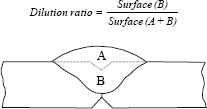
The chemical composition of molten metal results from the metal mixture added by the welding product and the base metal. The proportion of base metal in a weld bead is characterized by the dilution ratio (see Figure 4.4).
According to the process, the type of joint and the welding procedure, the proportion of base metal is more or less important and in the case of a multipass joint, it varies from one pass to another. However, the products of welding are balanced chemically so that their deposits “outside dilution” acquire the necessary mechanical properties under the cooling conditions corresponding to the most traditional thermal welding cycles. It should be understood that each time a welding material undergoes cooling transformation phases, the analysis of the metal added by the welding product which makes it possible to obtain the same mechanical properties is different from that of the base metal, because the cooling conditions during the manufacture of the latter are very different from those which are associated with welding. Thus, by dilution effect, the molten metal has an intermediate analysis between that of the added metal and that of the base metal and this analysis can vary from one pass to another in multipass welding. This is why the majority of the operating mode procedures require a check on the properties at various levels in the welded joint and, in particular, in the root zone where the dilution ration is the highest and consequently where the lowest impact strength values will often be found. In spite of these qualifications, the manufacturers are not spared unpleasant surprises while checking the properties of the assemblies during production if they have recourse to materials of various sources. This results from the fact that the qualification of the operating procedure takes the standardized designation of the base metal into account and that in the majority of cases, this is based on the product’s mechanical properties. Thus, according to the different manufacturing techniques available to them, the various steelmakers will use significantly variable analyzes to comply to the same standardized designation as the analyzes of three steels used indifferently by the same manufacturer show (see Table 4.2). If they are welded with the same filler product, these steels, although conforming to the required standard, will lead to very different analyses and mechanical properties of the molten metal in the zones where there is a high dilution rate.
Table 4.2. Examples of analytical variations in steels complying to the same standardized designation

Analytical characteristics of the deposited metal
The deposited metal comes from the fusion of the filler product in the atmosphere of the arc. The welding processes with a refractory electrode (TIG, plasma) generally takes place in an inert atmosphere to avoid rapid deterioration of the tungsten electrode. When these processes are employed, the analysis of the deposited metal is then very close to that of the filler; it differs only in the volatilization of various elements present, which are a function of their respective vapor tensions. Thus, a slight reduction will be noted in the manganese content in the deposited metal compared to the filler.
On the other hand, for all the other processes the arc atmosphere is deliberately more or less oxidizing because a light oxidation of the base metal’s surface aids electron emission and, thus the stability of the arc. This being the case, oxidoreduction reactions occur, mainly in the metal drops which transfer in the arc, so that the analysis of the deposited metal deviates notably from that of the filler. It is easy to take these chemical exchanges into account at the time the welding product is formulated, so as to adjust the alloying elements to obtain the content desired in the added metal but one will never be able, with these processes, to lower the oxygen content of the deposited metal to the level of that of the base metal (see Table 4.3). Oxygen being practically insoluble in the majority of metals, it will be found in the form of inclusions finely dispersed in the weld. In the case of steels, we will see later that under certain conditions these inclusions can play a key role at the time of the austenite transformation of the molten metal.
Table 4.3. Ranges of oxygen content variations in steel welds according to the processes and the types of welding products

In welding with a coated electrode (SMAW), there is another element whose content in the molten metal cannot be kept as low as we could wish: nitrogen. Indeed, although coatings of the coated electrodes always contain components which break up during fusion and generate at the level of arc gases in order to protect the metal droplets from the ambient air, the protection thus obtained is never perfect and we cannot avoid a certain amount of contamination. Because the process is manual, it is clear that the extent of this contamination depends on dexterity on the welder but, whatever it is, it is very difficult to have less than 100 ppm of nitrogen in the deposited metal, particularly in all-positional welding.
4.2.3. Microstructures in ferritic steel welds: relationship with impact strength characteristics
As in the HAZ, the mechanical properties of the molten metal depend on its structure and its chemical composition.
If it is easy to define a chemical analysis of the molten metal so as to make it compatible with the tensile properties of the base metal, it is not so simple from the perspective of toughness. Consequently, we will limit our comments here to the issue of impact strength, because this simple and inexpensive test is systematically employed in welding.
In a multipass joint, two types of zone can always be distinguished (see Figure 4.5): the first has preserved an as-solidified structure while the second has been “reaustentitized” during the execution of successive passes. The microstructural components of these various zones are in general very different. Except in the case of a strongly alloyed weld, the reaustenitized areas have a ferritic structure with a small proportion of pearlite because the percentage of carbon in welding products is always very low.
The toughness of this ferritic structure with equiaxial grains depends, as always in metallurgy, on the fineness of the grains. It is thus a function of the thermal welding cycle, which dictates the time spent in the austenitic state and the cooling speed and so the transformation temperature of the austenite. It also depends on the presence of elements such as titanium, niobium, vanadium, aluminum or boron, which limit grain enlargement at the reaustenitization phase. At all events, this reheated structure is generally not at the origin of problems of impact strength in welded joints.
On the other hand, the as-solidified zones can have very different structures from one joint to another and, therefore, considerable variations in terms of their impact strength characteristics, as illustrated in Figure 4.6.
The proportion of the as-solidified and reheated zones depends on the process and the welding conditions. In the case of TIG multipass welds or when using small diameter coated electrodes, a narrow bead width effectively ensures that the whole of the molten metal has a reheated structure. On the other hand, in submerged arc welds, the as-solidified zones never represent less than 50% of the molten metal and can even reach 90% in the case of double sided bypass welds.
Figure 4.5. Submerged arc welding: a) macrographic aspect; b) microstructure of the as-solidified zones; c) microstructure of the reheated zones

The proportion but especially the position of these two types of structure at the notch bottom of the impact test specimens will affect the result. Indeed, the fracture energy measured during this test is the sum of energy necessary to initiate a crack at the notch bottom and the energy necessary for it to progress and lead to the creation of two surfaces. The crack will be initiated under the pendulum impact as soon as the critical initiation stress which is specific to each microstructure is reached in one or other of them. Thus, the stress which develops at the notch bottom under the pendulum impact decreases from its center towards the sides. This is why, in a perfectly homogenous material, the rupture is always initiated in the notch center, while in a heterogenous material, initiation could be offset laterally if the microstructure located at the notch center has a critical cracking stress higher than that of an adjacent structure. Thus, when the most fragile structure is offset compared to the notch center, the initiation component of the rupture energy measured during the impact test is much higher than when this same structure is located at the center. As for the propagation energy, it can be readily conceived that it is a function of each microstructures’ size and their intrinsic characteristics.

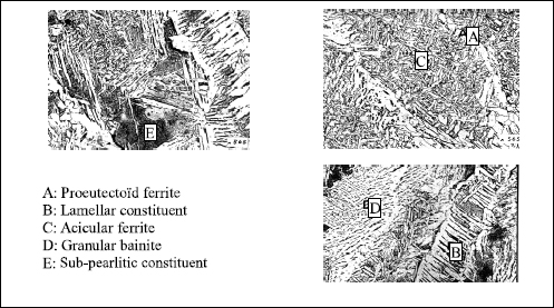
The principal microconstituents likely to exist in the as-solidified zones are represented in Figure 4.7.
In the IIS/IIW-999-88 document, the International Institute of Welding proposes a finer analysis and distinguishes more constituents, however, this is not the important point. Indeed, all metallurgists know that toughness is improved by refining the structure.
Under these conditions, it is clear, looking at the micrographies in Figure 4.7, that the as-solidified zones which lead to the best impact strength characteristics will be primarily made of acicular ferrite.
This microconstituent, which never appears in steels, exists in the molten metal only in the presence of certain inclusions which allow the intragranular germination of the ferrite at the time of the transformation of austenite [ABS 78, COC 78]. It is known that the existence of these inclusions depends on the oxygen content of the deposited metal but, so that there is intragranular ferrite germination, it seems necessary that these complex inclusions, which result from oxido-reduction reactions in fused metal and which are trapped during solidification, have locally on their surface Ti oxide TiO [STL 93] or a MnTi oxide, MnTi2O4 [BLA 99]. It should be understood then that titanium plays a fundamental role [CHA 83, EVA 97] and besides it is its variation (0.004 to 0.008%) which explains the difference between the structures and the impact strength values of the welds A and B in Figure 4.6. However, it is not enough to have a minimum of titanium so that it is found in one or other of the desired forms on the inclusion surface. What is more, it is necessary that the reaction kinetics which lead to the formation of inclusions allow this result. Thus, in addition to the oxygen content, the nature and the quantity of all of the deoxidizing elements present in the molten metal will play a part, whether they come from the wire or the base metal [BUR 88, DEV 83].
The complexity of these phenomena means that even today it is impossible to predict the presence of the germs necessary to the formation of acicular ferrite with a simple reading of a chemical molten metal analysis. Only a metallographical examination enables us to definitely determine the presence of this component.
These particular inclusions are necessary to achieve a structure rich in acicular ferrite and as a result a good toughness in all the welding zones (including the as-solidified zones). However, this condition is not sufficient because the proportion of acicular ferrite depends on the thermal welding cycle and the chemical composition of the molten metal which determines its hardenability.
Influence of cooling speed
In metallurgy, CCT diagrams make it possible to obtain a precise idea of the structure and hardness of a steel according to the cooling speed after austenitization. These diagrams are specific to each steel and each austenitization condition (austenitic grain size).
In welding, such diagrams do not exist and will undoubtedly never exist because the variations in cooling speed in the field of austenite transformation (Δτ 800/500 or Δτ 700/300) are always accompanied by a variation in the conditions of austenitization, but there is no correlation between these two factors: the increase in the welding energy, the preheating temperature, thickness of the parts to be assembled or the implementation of different welding processes do not have similar consequences on the upper (austenitic field) and lower parts (field of transformation) of the thermal cycle [BON 80].
In any event, if the necessary inclusions are present, it has been clearly shown [ANT 81] that an increase in the cooling speed leads, initially at least, to an increase in the proportion of acicular ferrite and is accompanied by an improvement in toughness (see Figure 4.8). Secondly, additional hardened structures (lower bainite and/or martensite) can be found if the hardenability of the molten metal is high.
Influence of alloying elements
The addition of alloying elements to a steel increases its hardenability by delaying transformations which proceed by germination and growth, and lowering the temperature at which martensitic transformation (Ms) begins. If the CCT diagram is considered, the principal effect of this additions is to shift the curves of the diagram towards the right.
Figure 4.8. Influence of the thermal cycle on the structure and the temperature transition — analysis of the molten metal: 0.066% C; 0.94% Mn; 0.62% Si; from [BON 80]

It is much the same for molten metal, except that the slowing of transformations by the addition of alloying elements seems to favor the “traditional” transformations more than acicular ferrite formation. That is easily explained when we consider that, for a field in which austenite is transformed into acicular ferrite to exist, specific inclusions must be present which play the part of preexisting germs. Then, the addition of alloying elements can have an effect on the germination speed of acicular ferrite but only on its growth.
Thus, at a constant cooling speed, the addition of alloying elements causes an evolution in the microstructure similar to that which the increase in cooling speed causes at a constant chemical composition: initially at least, the proportion of acicular ferrite increases because the transformations which preceded its formation are considerably slowed down; then, the acicular ferrite grains are refined then, finally, these are gradually replaced by an increasing proportion of martensite and/or lower bainite.
Figure 4.9. Influence of alloying elements and cooling rate on the transition temperature of the molten metal

However, from the perspective of mechanical properties, the increase in the cooling speed and the addition of alloying elements are not completely equivalent. Indeed, in the same microstructure, the presence of a greater quantity of alloying elements causes, through a solid solution effect, an increase in rupture strength, yield strength and hardness but also a reduction in impact strength values.
It is then possible to summarize the effect of the cooling speed and chemical composition on the impact strength characteristics in the following way (see Figure 4.9):
– when the content of an alloying element is low (low hardenability), we obtain a very coarse as-solidified structure primarily made up of proeutectoid ferrite and a lamellar component. Toughness is then badly effected whatever the cooling speed (high transition temperature);
– when the alloying content (Mn, Mo, etc.) is increased and if favorable inclusions are present, the acicular ferrite proportion increases, its grains become increasingly fine and toughness improves considerably;
– if the content of alloying elements is increased further beyond T1 for (Δt 8/5)1 or T2 for (Δt 8/5)2, a deterioration in the values of impact strength is observed because the negative effect of hardening through the solid solution effect related to the increase in the alloying elements becomes higher than the positive effect resulting from the increase in the quantity and fineness of the acicular ferrite;
– comparison of the two curves in Figure 4.9 shows conclusively that an increase in the cooling rate (Δt 8/5)1 compared to (Δt 8/5)2 always improves the impact strength.
In the absence of inclusions essential to the formation of acicular ferrite, granular bainite is first seen to appear then lower bainite. These structural variations are also accompanied by a certain improvement in impact strength values but they remain significantly lower than those obtained in the presence of acicular ferrite.
Influence of oxygen content
In ferritic steel welds, a minimum oxygen content is necessary so that the transformation of austenite into acicular ferrite can exist. This minimum content depends on the other deoxidizers present and increases particularly with the aluminum content. It is about 250 ppm when the aluminum content is lower than 0.015%; it can reach 350 to 400 ppm for an aluminum content of about 0.035 to 0.040%.
It is because this minimum is not reached that poor impact strengths are obtained at low temperature in ferritic steel welding carried out by means of high energy density processes such as plasma, electron beam and laser.
The oxygen content also gives a certain indication of the inclusion rate and this rate has a direct incidence on the ductile rupture energy: all things being equal otherwise, an increase in the inclusion rate generates a reduction in the ductile rupture energy (see Figure 4.10).
There thus exists an optimum oxygen parameter for ferritic steel welds when the required tensile characteristics are accessible to an acicular ferrite structure (<650 or 700 MPa) because the best tensile/toughness compromise will be obtained. Beyond this, structures of lower bainite or martensite will have to be resorted to and a maximum reduction in oxygen content sought so as to minimize the inclusion rate. Obviously this is also the case for austenitic stainless steel welds or, more generally, of face centered cubic materials which do not present a ductile/brittle transition.

Influence of nitrogen, niobium and vanadium
In ferritic steels, nitrogen can be associated with three metallurgical phenomena:
– solid solution effect: the nitrogen atoms in an interstitial position in the cubic centered iron lattice generate large distortions of the crystal lattice that cause an increase in the tensile and hardness characteristics, associated with a reduction in toughness. It is to these free nitrogen atoms that the most harmful effect is generally attributed;
– precipitation hardening: this hardening results from a coherent precipitation of nitrides or carbo-nitrides of elements with a strong affinity for nitrogen (in particular niobium and vanadium). This precipitation primarily occurs in the temperature range 400-650°C;
– ageing: this stems from the diffusion of nitrogen atoms in the interstitial solid solution towards the crystalline defects that strongly limits the possibilities of dislocation displacements.
An increase in the elasticity limit is then observed, while impact strength drops. This phenomenon really appears only at low temperatures (ambient/250°C).
In the welding of these steels, the increase in nitrogen content is observed to have a negative effect on impact strength in all the zones of multipass weldings, that is to say not only in the last pass, which has an as-solidified structure rich in acicular ferrite, but also in the reaustenitized zones which have an equiaxed ferritic structure with fine grains and the zones with an as-solidified structure but reheated to a value lower than Ac1 during the execution of subsequent passes [BON 86]. In these last zones, the increase in transition temperature with the nitrogen content is more marked when the welding contains a small quantity of niobium and, more still when it contains vanadium.
Niobium and vanadium are very seldom added voluntarily in welding products but they are necessary for TMCP (Thermal-Mechanical Controlled Processing) steel manufacturing, and are also found in certain quenched-tempered steels. Via a dilution effect, some will be found in molten metal and particularly in the root passes, where they will cause a reduction in impact strength values, which are increasingly significant the higher the nitrogen content. This embrittlement will be even more marked if the assembly has to undergo a post-welding relief treatment, because it will allow niobium carbo-nitrides and vanadium nitrides to precipitate more completely.
The titanium/boron effect
This effect results from the presence of a very small quantity of boron (typically 20 to 60 ppm) that considerably delays the appearance of proeutectoid ferrite in the austenitic grain boundaries during the cooling of the weld bead. Thus, the austenite transformation can occur primarily by intragranular acicular ferrite germination on the inclusions, provided that these have the necessary characteristics and are thus present on titanium oxide surface zones. When the whole chemical analysis of the molten metal is well balanced in terms of manganese, and possibly nickel, so that its hardenability is optimal for the thermal cycle undergone by the weld, the proeutectoid ferrite network is reduced to a fine edging, the remainder of austenite being transformed into acicular ferrite. What is more, if it is possible to resort to an addition of molybdenum, which is the case when a yield strength higher than 550 or 600 Mpa is sought, a synergic boron-molybdenum effect is thus obtained which makes it possible to remove the proeutectoid ferrite network completely and to obtain a structure only made up of acicular ferrite whose toughness properties are remarkable. Lastly, it should be noted that the action of titanium and boron is not limited to the increase in the proportion of acicular ferrite, in the zones with a rough solidification structure, it also causes a refinement of the ferrite grains in the reaustenitized zones (see Figure 4.11).
Our recourse to the titanium-boron effect thus makes it possible to achieve a notable improvement of impact strength values in all the weld zones and a better homogeneity of the properties in these various zones. However, these positive results are obtained only if the nitrogen content is low and perfectly controlled. This is why this effect was originally implemented in the filler products for the manufacture of large tubes by bypass multielectrode sub-merged arc welding. It was then used in filled rutile wire and gave this product a privileged position as it conformed to the strictest metallurgical specifications. On the other hand, it is not used in coated electrodes because this process does not allow a sufficient control of the nitrogen content in the added metal.
4.3. Principal welding defects
We will not deal with defects of a purely operational origin such as grooves, lack of penetration, sticking, etc. here; we will rather consider only internal defects, that is to say, hot cracks, cold cracks, reheating cracks and porosities.
We will endeavor to clarify the criteria which make it possible to identify these phenomena and to show the mechanisms of their formation in order to deduce the precautions we must take to avoid them or the remedies to be applied when the problems appear.
4.3.1. Hot cracking
Under this term, we include solidification cracks, liquation cracks and cracks resulting from a lack of ductility at high temperature.
Solidification cracks
These appear at the end of solidification. They can be internal or emerge on the surface but they are always localized in interdendritic spaces and thus follow the directions of solidification. Thus, they are perpendicular to the isotherms at any point. As they are formed at high temperature, they are oxidized in contact with the air when they emerge on the surface. Lastly, they are always broad because of contractions in the surrounding metal during cooling.
The factors that influence hotcracking are partly dependent on the analysis of the molten metal and partly on the welding procedure (see Table 4.4).
Figure 4.11. a) Rutile filled wire without Ti-B effect; b) same formula with addition of boron. Impact test notches positioned in the pass axis (zb) and in the mold axis (zr)


A long solidification period and the presence of constituents with a low melting point mean that the solid and liquid phases will coexist over a vast temperature range. During cooling in this field, the liquid is transformed into a solid while contracting (volume variation in solidification) while the solid already formed contracts according to its own dilation coefficient. It can be understood that the longer the solidification time, the greater the risks of insufficient material at the end of solidification and of a crack appearing in the zones which solidify last, i.e. in the interdendritic spaces.
Table 4.4. Factors leading to cracking on solidification
| Factors related to material | Factors related to the operational process and the welding process |
|---|---|
| Lengthy solidification | Certain weld bead shapes (concave surface, width/depth ratio <0.7) |
| Constituents with a low melting point | High speed of welding |
| Base metal with high elastic limit | Rigorous clamping |
The influence of the base metal’s yield strength and the clamping of the parts to be assembled are of a different nature. When the molten zone cools, it contracts so that stresses will develop if the shrinkage cannot freely take place. These shrinkage stresses will apply to the molten metal in the course of cooling, forcing it to distort, which it will be able to endure or not as the case may be. The greater the internal or external clamping thus limiting the deformations of the assembly, the greater these stresses will be.
Although often underestimated, the shape of the weld beads and the welding speed have a major influence. The zone which solidifies last concentrates the impurities because of their rejection in the liquid phase during solidification. This makes it chemically more sensitive to the risk of cracking and, when the weld has a concave surface, this zone is also smaller in its cross-section. Thus, shrinkage stresses are more likely to generate cracking than when the surface is convex (see Figure 4.13). In the same way, when a bead penetrates deeply (low width/penetration ratio), its edges are parallel so that the final stage of solidification affects its entire height (central column); on the other hand, when the form is triangular, solidification finishes on the bead surface, which reduces the risks of cracking. Lastly, a reduction in the welding speed, and thus the solidification speed, makes it easier for the remaining liquid to fill the gaps created between the interdendritic spaces by the reduction in volume related to the liquid to solid phase; thus, the risk of cracks appearing are reduced.

These considerations are general and thus apply to all types of materials, but to state that a lengthy solidification period or the presence of constituents with a low melting point worsens the risk of cracking is not in practice of any great use for the welding engineer who must use materials of whose characteristics he is often unaware. It is more in his interest to take account of these risks by using the material’s chemical analysis.
In the case of mild and low alloyed steels, Bailey [BAI 78] deduced from a factorial experiment the parameter UCS (Units of Crack Susceptibility) which characterizes susceptibility to the formation of cracks at solidification in submerged arc welding analyzing the molten metal:

with C* = 0.08 if C < 0.08% and C* = C if C > 0.08%.
He indicated its validity for the following values: C<0.23%; S 0.010-0.050%; P 0.010-0.045%; Si 0.15-0.65%; Mn 0.45-1.6%; Nb<0.07%; Ni <1%; Cr <0.5%; Mo <0.4%; V <0.07%; Cu <0.3%; Ti <0.02%; Al <0.03%; B <0.002%; Pb <0.01%; Co <0.03%. Later [BAI 94], he specified that an increase in chromium, molybdenum or vanadium beyond these values reduces the risk of cracking at solidification, while an increase in nickel and boron have a negative effect. However, he also stated that the harmful influence of boron was demonstrated only for values higher than 0.01%. In this same document, the author considered that the risk of cracking is negligible when the UCS parameter is lower than 10 and very large when it is higher than 30, value 20 corresponding to the threshold of appearance of cracks during the execution of fillet welds in the first publication.
From this formula, it is seen that carbon does not have an effect up to 0.08% but proves to be the most harmful element beyond this value, i.e. from the moment when solidification involves the peritectic reaction. That is broadly explained by the fact that the solubility of sulfur and phosphorus are much lower in austenite than in ferrite, so that the appearance of the peritectic reaction results in an increase in the segregation of these elements, thereby promoting the formation of interdendritic films with a low melting point and thus the risk of cracking.
The element coefficients which play a part in this UCS parameter are relative to submerged arc welds. They cannot be generally applied to other processes, in particular because other factors which have an influence on cracking (bead geometry, welding speed) differ enormously from one welding process to another. Nevertheless, the chemical elements with negative or positive effects remain the same. Faced with a problem of solidification cracking in a C-Mn or low alloyed steel weld, it will always be beneficial to reduce the content of elements C, S, P and Nb and to an increase in Mn and S in the molten metal. A wise choice of the filler product can contribute to increase Mn and Si but will not have an effect on the harmful elements because these elements do not vary significantly in welding products. In practice, if their concentration is at an unacceptable level in the molten metal, this is because they come from the dilution of the base metal. A procedure will then have to be implemented which makes it possible to minimize dilution and will, in extreme cases, involve preliminary buttering of the faces to be joined.
In the case of austenitic stainless steels, the risk of solidification cracking is closely related to the phases involved at this time. Indeed, depending on their chemical composition, austenitic stainless steel welds can solidify completely in austenite or primary austenite then ferrite, or in primary ferrite then austenite or, finally, completely in ferrite.
However, we have already seen that the solubility of impurities such as sulfur and phosphorus was much greater in ferrite than in austenite and that the segregation of these elements could lead to interdendritic film formation at a low melting point. If the results of the many studies relating to the cracking sensitivity of austenitic stainless steels are classified according to the mode of solidification [KOT 93], an increasing resistance is observed passing from the purely austenitic mode to the primary austenite mode, then to the completely ferritic mode and finally to the primary ferrite mode. The large resistance of the primary ferrite mode compared to the completely ferritic mode probably resulting from the fact that the mixed solidification ferrite + austenite generates a greater length of interfaces and thus minimizes the segregations.
Many diagrams exist for predicting the structure of the deposited metal added according to the content of alpha gene elements (chromium equivalent) and gamma gene elements (nickel equivalent), the first and best known of them being that established by Schaeffler more than 50 years ago [SCH 49]. However, the majority of these diagrams indicate the structure of the as welded metal after cooling to room temperature and this structure can be very different from that which existed at the time of solidification because, during cooling, the ferrite generally regresses into austenite. Suutala [SUU 83] proposed a diagram to forecast the solidification mode, in which he distinguishes the fields of solidification in primary austenite and primary ferrite. However, in our opinion, the most informative and best adapted diagram to modern day steels is WRC 92 (see Figure 4.14) because it marks out the zones corresponding to the four solidification modes and also gives, expressed in terms of Ferrite Number, the ferrite content after cooling.
From this diagram it is thus possible to evaluate the cracking sensitivity of a weld according to the position of the point being analyzed in the fields A, AF, FA or F; this analysis can be the result of a measurement or an evaluation starting from the analysis of the base metal, the deposited metal and the estimated dilution rate. The risk can also be evaluated by measuring the ferrite number of a standard weld representative of the proposed joints with an apparatus such as the feritscope MP30 since it can be seen in this diagram that a ferrite number higher than 4 corresponds in the majority of cases to welds solidifying in the FA field (most resistant) or F. If the representative point is in a zone at risk (A or AF, or FN <4), it will be found to be very beneficial, unless the specifications prohibit it, to modify the choice of filler product or the welding procedure (dilution rate) so as to fall inside the fields FA or F. Lastly, for the cases where that proves to be impossible, it will be absolutely essential to pay attention to the shape of the bead, to minimize clamping and to use a low welding speed as we indicated before.

Liquation cracks
Liquation cracks occur mainly in the base metal’s HAZ, in the vicinity of the bond zone. They can also occur in the molten metal during thermal reactivation by a later pass, but in this case are generally prolonged in the form of solidification cracks in the pass currently being made. They are localized in the part of the HAZ brought up to temperatures that conform to the material’s solidification interval, a period which will be longer, the greater the content of the material’s microsegregations of elements which support the formation of constituents at low melting point. Under the shrinkage effect associated with cooling, these partial fusion zones will be all the more likely to experience cracks the deeper they extend inside the HAZ. It is this type of mechanism which is frequently encountered during the welding of molded products; it is very close to the formation mechanism of solidification cracks in the molten metal.
Another cause of the appearance of liquation cracks can be the formation of a eutectic around a phase of the dissolution process in the matrix.
This can occur when a thermodynamic phase, stable at room temperature, is unstable at high temperature and its return into solution could not be complete or its chemical homogenity reached because of the speed of the thermal welding cycles in regard to the kinetics of dissolution and diffusion. In this case, a liquid phase will appear inside the HAZ and will penetrate the surrounding grain boundaries, entailing their liquation and their cracking upon cooling because of shrinkage.
The sensitivity of any material to liquation cracking can be evaluated by means of hot tensile tests conducted via a simulation of a thermal welding cycle during the heating phase and the cooling phase (see Figure 4.15). This test makes it possible to determine the difference between the temperature at which the reduction in the rupture area becomes zero after heating and the temperature at which a certain capacity for deformation is restored on cooling. The greater the difference, the more susceptible the material is.
Figure 4.15. Hot ductility of the Cabot 214 alloy containing (a) 2 ppm of boron, or (b) 30 ppm; from [CIE 93]

This sensitivity to liquation cracking by is thus an intrinsic characteristic of the material; it depends on all of the chemical elements present, their distribution and the microstructure, i.e. that the welding process has little influence on the result unless using a filler product whose melting point is significantly lower than that of the base metal (braze welding).
Cracks due to lack of hot ductility (ductility dip cracking)
During cooling from the liquid state, many industrial alloys enjoy a temperature range in which the liability for deformation is notably lower than for the temperatures either side. The cooling curve in Figure 4.15a makes it possible to predict such behavior.
This decline in ductility, which is more marked the lower the deformation speed, is in the vicinity of the alloy’s recrystallization temperature. It can be at the origin of intergranular cracks both in the HAZ as well as in the molten metal, due to shrinkage caused by the weld cooling [HEM 69] but this type of cracking is seldom evoked in the case of ferritic steels. In these steels, however, certain authors [LIM 96] consider that these intergranular cracks can be prolonged, after complete cooling, by transgranular cracks induced by hydrogen, and would be at the origin of herringbone cracks (see following section).
On this subject, the bibliography is more descriptive than explanatory; nevertheless, it seems that there still, sulfur accentuates the phenomenon.
4.3.2. Cold cracking
These cracks appear at low temperatures (lower than 200°C). Thus, they are fine and do not have an oxidized surface. They do not have a particular orientation compared to the microstructure. They generally develop in the HAZ but can sometimes occur in the molten metal when it has a very high elastic limit. They derive from the stress field, which explains why they occur in the concentration zones which constitute the surface defects (poor wetting, grooves) or discontinuities related to the assembly design (partial penetration for example).

These cracks require the combination of three factors to occur:
– a not very ductile structure (martensite),
– stresses,
– hydrogen.
The respective influence of these three factors is perfectly highlighted by means of implant tests. To carry out these tests, cylinders of the material under consideration are taken. A notch of well defined geometry is machined close to one of the ends. The bar is placed in a support plate (see Figure 4.17) then a weld bead is made so that the notch of the bar is located in the HAZ of the weld bead. During cooling, a load is applied to the other end of the bar and is maintained for several days. The specimen is then cut open in order to determine whether cracks have developed at the notch extremity.
The test is repeated by applying various loads in order to evaluate the minimal cracking load of the structure in the notch bottom. It is also repeated by modifying the welding conditions, which makes it possible to highlight the influence of Δt 800/500 and to plot the cracking curve as it appears in Figure 4.16. In parallel the hardness curve under the bead is plotted according to the same Δt 800/500 parameter, the hardening evolution in fact representing the structural evolution.

We thus see in Figure 4.17 that for low Δt 800/500 parameters which are associated with a martensitic structure (peak of the hardness curve), the cracking stress is very low but, as soon as the structure is no longer 100% martensitic, the cracking stress increases significantly. The steel considered in this example being of type E36, it can moreover be seen that in this figure there will be no risk of cracking if Δt 800/500 is higher than 7 or 8 seconds, since then the coarse grain zone is able to support a stress higher than the elastic limit of the base metal without fissuring, which cannot occur because that would generate the deformation of the base metal and its stress relaxation.
All steels have a behavior similar to that in Figure 4.17 where the relation between cracking stress and structure is clearly seen.
The tests corresponding to this figure were carried out using a welding product whose diffusible hydrogen content was of 5.5 ml per 100 g of metal deposited. The same tests can be reproduced with other hydrogen contents in order to evaluate the influence of this third factor.
In Figure 4.18 we see that when diffusible hydrogen content increases, cracking stress significantly decreases whatever the Δt 800/500 considered. Thus, hydrogen seems a fundamental determinant of cold cracking. However, even when hydrogen is in a reduced quantity, a low stress is enough to cause cracking if the structure is completely martensitic. Thus, wherever possible, it will be necessary to choose welding conditions (welding energy, preheating) which avoid the formation of a 100% martensitic structure in the HAZ.

However, this is not possible with all steels. Indeed, some, like martensitic stainless steels for example, have a hardenability such that to avoid the martensitic transformation, cooling should last several days. To weld such steels it is imperative to ensure that hydrogen has been expelled before letting the assembly cool in the temperature range, otherwise cracking may appear (under 200°C). This is the aim of post-heating.
The crack curves in the preceding figures relate to the HAZ but the influence of hydrogen, the stress and the structure which these figures illustrate turns out to be identical when tests are carried out by taking extracts from the deposited metal [DEB 92].
As we indicated previously, cold cracking can occur in molten metal when steels of high elasticity limits are welded. Generally, it is in this case transverse across the bead but can also be longitudinal when a discontinuity exists under the bead root (partial penetration) or take the appearance of a herringbone crack (microscopic cracks angled at 45° to the welding direction) in welds with intermediate tensile characteristics [MOT 82]. This transfer of cold cracking localization away from the HAZ towards the molten metal is increasingly likely the higher the elastic limit of the deposited metal, given that welds are made with steels of modern design whose carbon content is low. Thus, during the welding of these steels, it is no longer the analysis of the base metal which dictates the preheating temperature required to avoid cracking in the HAZ, but the analysis of the molten metal in order to avoid bead cracking.
An interesting means of reducing the risk of cold cracking and consequently preheating temperature during the welding of these steels consists of using a filler for the execution of the root passes for “X” or “K” shaped assemblies, the remainder of the joint being filled with a filler product akin to the mechanical characteristics of the base metal. By doing this, it has been shown that the pre-heating temperature can be reduced by 50 to 100°C, a reduction of 50°C when compared to the use of a single product, and this of course without affecting the overall tensile characteristics of the joint [VUI 94]. In many cases, this amounts to eliminating the need for preheating, which, in addition to presenting a direct and immediate economic advantage for the manufacturer, considerably improves working conditions for welders and generally results in a reduced rate of operational defects, and therefore of repairs. Curiously, this practice is still not very widespread today.
The actions required to avoid cold cracking are thus derived from all the above considerations, and are recapitulated in Table 4.5.
4.3.3. Reheat cracking
Reheat cracking, intergranular in nature, occurs primarily in the coarse grain HAZ and occasionally in the molten metal. It begins during the post welding heat treatment or in service at high temperature [DHO 92]. It relates to low alloyed steels containing carbide-forming elements (Cr, Mo, V) but also certain austenitic stainless steels such as steel AISI 347, as well as precipitation hardening nickel alloys (Inconel 800H for example).
Table 4.5. Actions to take to avoid cold cracking
| 1) Minimize the quantity of hydrogen introduced into the weld pool | |
| – Cleanliness of the joint – Choice of welding products – Heating and conservation of the products (except if cases of airtight stocking) |
Moisture, oil, grease, etc. Low diffusible hydrogen. According to supplier recommendations. |
| 2) Wherever possible, use a filler product with very low elastic limit and very low hydrogen content for the execution of the first pass and the secondary pass of thick assemblies | |
| 3) Control the welding conditions to avoid the formation of a martensitic structure | |
| – Welding energy – Pre-heating – Temperature between passes |
To choose starting from the under bead hardness curves according to Δt 800/500 and the IRSID graph for example [COL 77] |
| 4) Envisage a postheating to evacuate hydrogen before cooling (case of steels having a great hardenability), always associate with a preheating to avoid cooling lower than the critical temperature before post-heating is effective | |
| 5) Minimize the internal or external stresses | |
| – Welding procedure – Clamping |
|
Such cracking derives from the relieving of strong residual stresses resulting from manufacture when the deformations which accompany it are concentrated at the level of the grain boundaries. This is the case for the coarse grain HAZ of precipitation hardened materials because, during welding, the carbides which harden these alloys are put back in solution in the zones taken to a very high temperature in the vicinity of the bond zone and remain during cooling because of the speed of the welding thermal cycles.
During a later reheating, in service or during the post welding heat treatment, the carbides will precipitate inside the grains on the dislocations created by strain hardening that results from thermal cycles. This will reinforce the matrix considerably, so that the creep deformations associated with stress relief will locate themselves on the level of the grain boundaries which cannot support them.
This type of crack thus relates primarily to thick assemblies of materials designed to resist creep, the thickness inducing a high level of residual stresses. However, the risk is not only related to the nominal analysis of material, it is also a function of the impurity content (S, P, As, Sb) and residuals (Cu, Sn), because these elements segregate to the level of the grain boundaries and weaken them.
Various methods are used to evaluate susceptibility to reheat cracking [DHO 98, TAM 95], but our preference is to reduce the area measurement during hot tensile isothermal tests of specimens in which, by thermal simulation, the structure of the coarse grain zone has previously been reproduced. Indeed, it is considered that the risk is very low when no reduction of area value lower than 20% is recorded regardless of the test temperature; on the other hand, it is very high when the striction becomes lower than 10%.
In practice, to minimize risks when a susceptible material must be used, it is of great importance to:
– design the joints to reduce clamping as far as possible,
– choose a welding product that has the lowest hot tensile characteristics compatible with the application,
– use a low energy welding process in order to limit the pass volume and to thus reduce the dimension of the coarse grain HAZ,
– distribute the passes to reaustenitize the coarse grain zones created by the preceding passes and thus decrease the grain size,
– envisage welding sequences to minimize residual stresses,
– ensure a good wetting of the finishing passes and the absence of grooves so as to avoid stress concentrations.
In addition, the handling of the post-welding heat treatment can have a capital incidence on reheat cracking since it has been shown in the laboratory and production, that the cracking of a CrMoV steel which has a low ductility in the interval 550-650°C can be avoided by carrying out a stage at a temperature of about 450°C then very quickly crossing the field of low ductility in order to reach the treatment temperature [PIL 86].
4.3.4. Porosities
We will distinguish four mechanisms likely to engender porosities in molten metal:
– the instability of the gas capillary for weldings carried out by means of HDE processes,
– an excessive gas pressure under the bead root,
– a dissolved gas content in molten metal higher than the solubility limit in solid metal at the solidification temperature,
- a chemical reaction within the weld pool giving rise to a gas.
The HDE processes involves keyhole work. This implies that the weld pool is maintained in balance thanks to the gas vapor pressure which is exerted on the capillary walls created by the volatilization of metal under the influence of a very high density plasma arc, laser beam or electron beam. When the operating conditions allow us to maintain a perfectly stable state of balance, the liquid wall located at the back of the capillary can collapse in a more or less periodic way and enclose part of the metal vapors which maintained it, thus forming porosities. These hydrodynamic porosities could generally be avoided by modifying the power density distribution of the incidental beam (point of focusing, vibration, etc.) and by reducing the welding speed.
Figure 4.19. Pre-painted sheet fillet weld — porosity resulting from paint decomposition under the bead

When porosities result from excessive gas pressure under the bead root, they take a lengthened form and maintain a connection with the zone at the origin of this excessive pressure.
The pressure can result from the heating of air imprisoned under the bead; this is typically the case for butt welds with a preparation by joggling when the penetration is insufficient. It can also derive from a gas release that results from the decomposition or volatilization of product coating sheets, as is the case during fillet welding of pre-painted sheets (see Figure 4.19) or lap welding with galvanized sheets. Lastly, its origin may be a degasification of the faces to be assembled; it is, for example, the nitrogen released from the plasma air cut faces which explains many porosities which are formed in the first pass of a butt welded assembly when there is no lower edge spacing of the joint (see Figure 4.20).
Figure 4.20. Texture test after the first pass of a submerged arc butt welded joint of as-cut sheets cut by the plasma air process

The sudden reduction in the solubility of a gaseous element at the time of the passage from the liquid state to a solid state is the leading cause of porosities in the weld beads because this variation is common to all materials (see Figure 4.21). Indeed, when the dissolved gas concentration in molten metal is higher than the solubility limit in solid metal at the solidification temperature, there is a rejection of gas to the solid-liquid interface. This causes the liquid to experience a local increase in the dissolved gas content and, when this becomes higher than the solubility limit in the liquid, a gas bubble is formed.
In welding, the weld pool can be contaminated by atmospheric nitrogen and oxygen if protection is not assured, or by hydrogen coming from welding products that have absorbed moisture, by water vapor which condenses on the surface of a cold sheet, an escape in the coolant circuit of the torch, or the decomposition of oil or grease present at the surface of a badly prepared joint. Oxygen is generally not at the origin of porosities because it reacts with the majority of materials to form oxides. In ferritic steels and nickel alloys not containing nitride forming elements (Ti, Al, Nb), it is in general the nitrogen which is at the origin of porosities, while it is hydrogen in aluminum alloys but also in austenitic stainless steels, although they are more resistant than light alloys.
Figure 4.21. Evolution of solubility with temperature: a) hydrogen in various pure metals [LAN 99]; b) nitrogen in pure iron [KOU 87]

A chemical reaction giving rise to a gas within the weld pool constitutes the last cause of porosities which we will deal with here. Formation of carbon monoxide was at the origin of porosities which were inevitably formed during TIG welding of rimmed steels unless a filler very rich in deoxidizers was used. However, even if we no longer encounter this kind of steel, the CO release in molten metal can still occur when the residual oxygen of steel is present in the form of silicates, because at very high temperature (>1,600°C) they can be reduced by the carbon of the steel. This reaction is particularly intense during electron beam welding because the surrounding vacuum moves thermodynamic balances. It also favors this reduction to the extent that it becomes impossible to obtain a sound weld, unless the steel contains residual aluminum (approximately 0.02%), aluminates being more stable than carbon monoxide at the temperature of the weld pool (see Figure 4.22). Steam formation in the weld pool can also be at the origin of porosities. This will occur in the presence of hydrogen with materials for which the enthalpy of oxide formation is lower in absolute value than that of steam at the temperature of the weld pool. This is the case for copper, particularly when it is not deoxidized; it is also the case for pure nickel, Monel metal and even certain nickel-chromium-iron alloys [LAN 99]. There is only one remedy: use filler products which contain powerful deoxidizers such as titanium and aluminum to avoid this reaction.
Figure 4.22. Surface aspect and X-ray on a section of EB welds of XC 38 (Al = 0.002%): a) without insertion; b) with insertion in the mating plane of an aluminum foil 0.02 mm thick

4.4. Bibliography
[ABS 78] ABSON, DOLBY R.E., HART P.H.M., “The role of non-metallic inclusions in ferrite nucleations in carbon steel weld metal”, Proceedings of Trends in Steels and Consumables for Welding, The Welding Institute, Paper no. 25, London, 14-16 November. 1978.
[ANT 81] ANTUNES M., BONNET C., “Application d’un essai de trempabilité à la recherche des facteurs ayant une influence sur la formation de la ferrite aciculaire”, Journées d’information Métallurgie de la Zone Fondue, Société Française de Métallurgie/Société des Ingénieurs Soudeurs — Section sud-est, Conférence no. 9, Publication de la Soudure Autogène, 1981.
[BAI 78] BAILEY N., JONES S.B., “The solidification cracking of ferritic steel during submerged arc welding”, Welding Journal, p. 217s-231s, August 1978.
[BAI 94] BAILEY N., Weldability of Ferritic Steels, Abington Publishing, 1994.
[BLA 99] BLAIS C., L’ESPÉRANCE G., EVANS G.M., “Characterisation of inclusions found in C-Mn steel welds containing titanium”, Science and Technology of Welding and Joining, vol. 4, no. 3, p. 143-150, 1999.
[BON 80] BONNET C., “Relation Structure — Résilience dans les soudures d’aciers doux et faiblement alliés brutes de solidification”, Soudage et Techniques Connexes, p. 3, July- August 1980.
[BON 86] BONNET C., GASPARD-ANGELI A., “Influence de la teneur en azote sur la résilience des soudures d’aciers C-Mn”, Soudage et Techniques Connexes, p. 3, May-June 1986.
[BUR 88] BURKHARDT J., LAU T., NORTH T.H., L’ESPÉRANCE C., “Effect of aluminum on the Ti-O-B-N balance in submerged arc welding”, Welding Journal, p. 25-30, August 1988.
[CHA 83] CHARPENTIER J.P., BONNET C., “Effect of deoxidation residues in wire and of some particular oxides in CS fused fluxes on the microstructure of submerged-arc weld metal”, in Proceedings of the Effects of Residual, Impurity and Microalloying Elements on Weldability and Weld Properties, The Welding Institute, Paper no. 8, London, 15-17 November 1983.
[CIE 93] CIESLIAK M.J., “Cracking phenomena associated with welding”, ASM Handbook, vol. 6, p. 88-96, 1993.
[COC 78] COCHRANE R.C., KIRKWOOD P.R., “The effect of oxygen on weld metal microstructure”, Proceedings of Trends in Steels and Consumables for Welding, The Welding Institute, p. 103, London, 14-16 November 1978.
[COL 74] COLLECTIF, Courbes de transformation des aciers de fabrication française, edited by the CPS, 1974.
[COL 77] COLLECTIF, Courbes Dureté/Paramètre de refroidissement en conditions de soudage, collection established at the IRSID, 1977.
[DEB 92] DEBIEZ S., GAILLARD L., MALTRUD F., Etude de la soudabilité d’un acier de nuance E690 T+R de Sollac avec des produits d’apport à bas et très bas hydrogène, Rapport Institut de Soudure no. 28406, 1992.
[DEV 83] DEVILLERS L., KAPLAN D., MARANDET B., RIBES A., RIBOUD P.V., “The effect of low level of some elements on the toughness of submerged-arc welded CMn steel welds”, Proceedings of the Effects of Residual, Impurity and Micro-Alloying Elements on Weldability and Weld Properties, The Welding Institute, London, 15-17 November 1983.
[DHO 92] DHOOGE A., VINCKIER A., “La fissuration au réchauffage — revue des études récentes (1984-1990)”, Le Soudage dans le Monde, vol. 30, no. 3-4, p. 45-71, 1992.
[DHO 98] DHOOGE A., “Survey on reheat cracking in austenitic stainless steels and Ni base alloys”, Welding in the World, 41, p. 206-219, 1998.
[EVA 97] EVANS G.M., BAILEY N., Metallurgy of Basic Weld Metal, Abington Publishing, 1997.
[GAR 75] GARLAND J.G., KIRKWOOD P.R., “Towards improved submerged arc weld metal toughness”, Metal Construction, p. 275-283, May 1975, p. 320-330, June 1975.
[HEM 69] HEMSWORTH B., BONIZEWSKI T., EATON N.F., “Classification and definition of high temperature welding cracks in alloys”, Metal Construction and British Welding Journal, p. 5-16, February 1969.
[KOT 92] KOTECKI D.J., SIEVERT T.A., “WRC-1992 constitution diagram for stainless steel weld metals: a modification of the WRC-1988 diagram”, Welding Journal, p. 171s-178s, May 1992.
[KOT 93] KOTECKI D.J., “Welding of stainless steel”, ASM Handbook, vol. 6, p. 677-707, 1993.
[KOU 87] KOU S., Welding Metallurgy, John Wiley & Sons Inc., 1987.
[LAN 99] LANCASTER J.F., Metallurgy of Welding, Abington Publishing, 1999.
[LIM 96] LIMU H., HANNERZ N.E., “Influence of vanadium and niobium on weld solid state cracking”, Int. J. for the Joining of Materials, vol. 8, no. 4, p. 134-144, 1996.
[MOT 82] MOTA J.M.F., APPS R.L., “Chevron cracking — a new form of hydrogen cracking in steel weld metals”, Welding Journal, p. 222, July 1982.
[PIL 86] PILARCZYK J., DEBSKI E., “Reheat cracking in low alloy steel weldments and welded structures”, Proceedings of 3rd International Conference Joining of Metals (JOM-3), Helsinki, Finland, December 1986.
[SCH 49] SCHAEFFLER A.L., “Constitution diagram for stainless steel weld metal”, Metal Progress, 56, S 680, 1949.
[STL 93] ST LAURENT S., Etude de l’influence du Bore, de Titane et de l’Azote sur les propriétés de la zone fondue de dépôts soudés d’aciers microalliés, Thesis, University of Montreal, Ecole Polytechnique, July 1993.
[SUU 83] SUUTALA N., “Effect of solidification conditions on the solidification mode in austenitic stainless steels”, Metall. Trans., 14A, p. 191-197, 1983.
[TAM 95] TAMAKI K., SUZUKI J., IMAI I., HORII Y., KUMAGAI T., “Effects of impurities and alloying elements on reheat cracking sensitivity of 720 N/mm2 class high-strength steel”, Welding International, vol. 9, no. 12, p. 960-966, 1995.
[VUI 94] VUIK J., VAN WORTEL J.C., VAN SEVENHOVEN C., “Application of very low yield strength consumables in the root pass of weldments to avoid preheating”, Welding in the World, vol. 33, no. 5, p. 362-369, 1994.
1 Chapter written by Christian BONNET.