Chapter 5
Welding Products 1
5.1. Coated electrodes
5.1.1. Constitution of coatings: consequences
The classification standards of welding products distinguish several types of coated electrodes according to the kind of coating.
An electrode coating is always composed of many constituents which provide various functions:
– mineral products which act on fusion characteristics, contribute to the protection from the surrounding atmosphere of the drops and the weld pool by breaking up into a gaseous emission under the influence of the arc heat and constituting a slag whose physico-chemical characteristics have a major influence on the operational characteristics of the electrode;
– metal products which by being combined with metal resulting from the fusion of the electrode core, make it possible to adjust the analysis of the weld metal so as to obtain properties equivalent to those of the steel used in the welded joint;
– organic materials added in small quantity in basic coatings as an extrusion agent and which will be destroyed during high temperature heating of these electrodes. They are present in much larger quantities in electrodes baked at low temperature (cellulose, rutiles, etc.) because the decomposition of these products in the arc causes a release of hydrogen which confers operational characteristics on them which prove valuable in many applications;
– binders which make it possible to obtain a solid coating which adheres to the metal core. There are in general simple or complex silicates of sodium, potassium or lithium, which in addition to their adherence function act on the arc characteristics because of the low ionization potential of the alkaline elements.
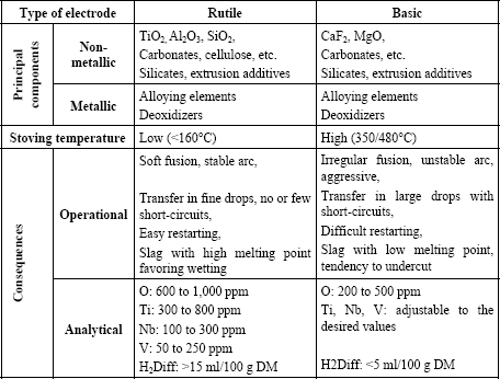
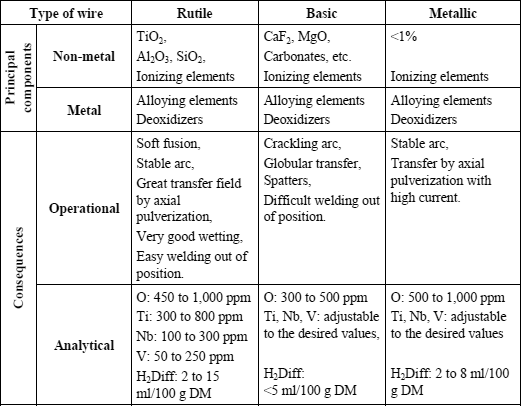
In industry, basic and rutile electrodes are the most commonly used. Table 5.1 makes it possible to compare on the one hand the constituents and the baking conditions and, on the other hand, the consequences which result from this both for operational properties and chemical analysis of the deposited metal.
Thus, it appears that rutile type electrodes present the best properties in use: a very good arc stability, transfer of metal in fine drops which generally results in a low level of spatters and lower fume emission than the basic electrodes, a very good bead wetting and a very easy restart from cold.
However, by its nature, this slag has an influence on the content of residual elements in the deposited metal, elements which are in general not desirable from the perspective of optimizing mechanical properties.
The oxygen content of the deposited metal can vary according to the nature and the quantity of the deoxidizing elements present in the coating, nevertheless, it cannot be lowered to the level which can be reached with a basic electrode. This results in a more significant inclusion content and consequently in a lower ductile fracture energy during impact tests.
The titanium content of the deposited metal cannot be adjusted, as we would wish, in order to optimize the mechanical properties. Indeed, the slag being mainly composed of rutile elements (titanium oxide TiO2), some titanium is inevitably transferred to the deposited metal in variable quantities according to the oxidoreduction reactions and the metal-slag exchanges which occur in the arc and at the interface with the weld pool. These reactions depend on all the chemical elements present, which must be balanced according to the various mechanical characteristics that the weld must meet (tensile strength, yield strength) and depending on the type of steel that we have to weld.
The niobium and vanadium content of the deposited metal cannot be lowered beyond a certain point because these elements exist as impurities in the natural rutiles used in the manufacture of welding products. The use of synthetic rutiles, which are therefore very pure, is possible but not common because its cost is significantly higher than that of the natural rutiles.
The diffusible hydrogen content of welds created with rutile electrodes is always very high. This results from the presence of organic materials added to facilitate extrusion and to improve the arc’s characteristics. However, it is also a result of low baking temperatures which makes it possible to eliminate only a small proportion of the water incorporated with the silicate and it does not break up the extrusion agents.
Thus, rutile electrodes are valued for their user-friendliness and the creation of a weld bead, whereas basic electrodes are essential when the joints to be made must satisfy severe metallurgical quality standards.
A basic electrode must satisfy the required mechanical properties of the steels which it is intended to weld (tensile, impact strength, CTOD, creep, etc.). Many analytical combinations make it possible to obtain the tensile characteristics sought in the deposited metal, but the solutions that satisfy both the tensile and toughness characteristics are much more limited. This is increasingly true the higher the tensile properties. In addition, the chemical balance retained for an electrode must be the most robust possible, i.e. it must satisfy the various requirements in spite of the variations inherent in any industrial production, and that, in a broad field of welding conditions (thermal cycles). Lastly, a basic electrode must be designed so that the diffusible hydrogen content in the deposited metal is as low as possible in order to avoid any risk of cold cracking, while minimizing or even precluding pre-heating and post-heating.
5.1.2. Basic electrodes and diffusible hydrogen
The determination of the diffusible hydrogen content of welding products is problematic because, due to its small size, the hydrogen atom diffuses easily and escapes from steel even at room temperature, so that it is impossible to know the exact quantity of hydrogen introduced during welding. Faced with this difficulty but also the need to classify welding products according to their cold cracking susceptibility, the determination of the diffusible hydrogen content is the subject of strict guidelines which very precisely describe the methodology to be used. This methodology must be respected scrupulously if extreme variations in results (as much as double) are not to be recorded (ISO 3690 or AWS 4.3-1993).
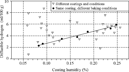
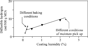
The diffusible hydrogen content is generally expressed in milliliters per 100 grams of deposited metal (ml/100 g DM). It is naturally a function of the moisture contained in the welding product, but Figure 5.1 clearly shows that there is no general relation between these two measurements and we see in Figure 5.2 that even while being limited to a particular electrode coating, two different relations exist according to whether the variation of moisture results from a modification of the baking conditions or from moisture pick-up.
In fact, the complexity of the relations connecting diffusible hydrogen and the coating humidity derives from the fact that water exists in various forms: the water known as free which corresponds to the first water state taken up during an exposure to a damp atmosphere, and the water called water of crystallization, which is chemically bound to the various electrode constituents. If the temperature of the coating is raised, free water escapes as soon as it exceeds 100°C, while water of crystallization is released only at much higher temperatures which depend on the type of bond, and therefore the material from it is derived. Thus it can be seen that for the same quantity of water in the electrode coating, the higher the extraction temperature of this water, the more it will be released near the arc in the course of welding and the greater the transfer of hydrogen in the weld pool. Thus, when the electrode baking temperature is lowered during the manufacture of a basic electrode, a decreasing quantity of water of crystallization is eliminated from the coating material. This small variation of residual water from the baking results in an increase in the diffusible hydrogen content, much greater than a similar variation of water content in the coating when it results from moisture pick-up (see Figure 5.2). As a corollary, it is clear that to impose a maximum moisture content in the purchase specifications of electrodes (or flux for submerged arc welding) with the aim of obviating the risk of cold cracking has no practical logic, since no universal relation connecting moisture to diffusible hydrogen exists. On the other hand, using the humidity measurement, which is much simpler and more rapid than the measurement of diffusible hydrogen, to verify the manufacturing consistency of a given electrode at the end of the baking process is a practice that is viable and accepted. This is acceptable because, for each electrode, a single relation exists between the residual baking humidity and diffusible hydrogen.
Today, the majority of welding product manufacturers have a range of basic electrodes with very low levels of diffusible hydrogen. The best of these guarantees a level lower than 3 ml/100 g of deposited metal with rods from a newly opened package. Such a result can be achieved only by a rigorous selection of raw materials, a high baking temperature and airtight packaging, so as to avoid moisture pick-up during product storage [LED 92]. In general, these electrodes are also characterized by a low moisture pick-up when they are exposed to a humid atmosphere.
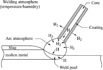
However, the diffusible hydrogen content of the deposited metal is not only a function of the hydrogen brought in one form or another by the welding product. In the case of coated electrodes, the gas flow resulting from the decomposition of the coating’s constituents is not sufficient to prevent an exchange with the surrounding atmosphere (see Figure 5.3). Thus, the partial hydrogen pressure at the arc level and, consequently, diffusible hydrogen in the deposited metal increase in concert with the absolute humidity content of the surrounding atmosphere (see Figure 5.4).
Figure 5.4. Influence of atmospheric water content on diffusible hydrogen in the deposited metal (SAF data)
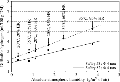
Dickehut and Ruge proposed a diagram which makes it possible to know the diffusible hydrogen content under any temperature and pressure conditions, provided that we know the result under any single condition. This graph is not universal because atmospheric exchanges are necessarily dependent on the protection given to the electrode (crater depth, volume of released gas, etc.). Nevertheless, the experiment shows that as a first approximation it encompasses the behavior of the majority of low hydrogen electrodes of type AWS 7018 currently marketed.
5.2. Fluxes for submerged arc welding
5.2.1. Fused fluxes and granular fluxes: advantages and disadvantages
Fluxes for submerged arc welding can be produced by fusion or granulation.
Fused fluxes are manufactured from coarse raw materials which are mixed before being introduced into an electric furnace. They are then brought up to a temperature of about 1,600°C which makes it possible to obtain a chemically homogenous liquid product. This product is then cast on a plate, strongly cooled in order to confer a glassy structure after solidification and cooling to room temperature, thus preserving a perfect chemical homogenity.
This glass is then crushed and sieved so as to obtain the desired granulometric distribution. In an alternative manufacturing process, the liquid product is atomized in a water jet instead of being cast on a plate, which obviates the crushing operation.
The manufacture of granular fluxes begins with a dry mixture, formed from raw materials which in this case have a very fine granulometry (in general lower than 300 microns). After homogenization of the dry mixture, mixing is carried out by adding a simple or mixed silicate of sodium, potassium or lithium. Granulation, i.e. the agglomeration of small particles taken from various raw materials, can then take place thanks to the silicate binder. This is followed by a pre-drying stage often using a fluidized bed, then by baking at a temperature of about 500°C if the manufactured flux contains carbonates or at higher temperature (800°C approximately) even if it does not contain any.
Fused fluxes and granular fluxes each have their advantages and disadvantages.
Each grain of a fused flux is chemically identical to the others, unlike those of a granulated flux whose particles are not chemically homogenous. Thus, it is possible to manufacture fused fluxes in which a particular element must be present in very small quantity, without risking segregation formulae (boron for example). This is particularly critical for a granular flux.
The manufacture of fused fluxes does not require the use of binder. This brings two advantages and one disadvantage compared to granular fluxes:
– the moisture pick-up of fused fluxes is practically negligible, since water is only adsorbed on the grain surface. That of a granular flux is on the contrary much greater because the binder reacts with atmospheric humidity [GAS 86];
– the fused flux grains are more solid than those of granular fluxes which makes them more suitable for recycling;
– however, the binders used in the manufacture of granular fluxes generally create better arc stability than fused fluxes.
Fused fluxes, unlike granular fluxes, cannot contain either ferro-alloys or deoxidizers because these would be oxidized during production in the liquid state. This enables the slag to be reground after welding and reused, mixed with new flux — a practice that can be economically beneficial for certain large industries whose flux consumption is high (manufacture of tubes for example) [GAS 86]. On the other hand, it precludes analytic adjustments and control of the oxygen content of the deposited metal something which can be achieved with a granular flux by the addition of deoxidizing elements.
Today, granular fluxes are most commonly used in Europe and the USA, whereas fused fluxes are still very popular in Japan and Russia.
5.2.2. Roles of flux: metallurgical aspects
Submerged arc welding involves the use of a solid or cored wire and a flux, the arc striking into the flux from the end of the wire to the parts to be assembled. The flux must perform two fundamental functions: it must provide good arc stability and it must protect the weld pool and the metal drops from atmospheric nitrogen and oxygen contamination during their transfer in the arc. Flux also has an important effect on the shape of the weld bead (wetting and penetration). This is because it alters the power distribution in the arc as well as the physical characteristics of the slag, which result from its fusion and the oxido-reduction reactions occurring during welding. This is why, depending on its formulation, a flux can be more or less well adapted to fillet welding, high speed welding or multielectrode welding. Yet, from a strictly metallurgical perspective, the fundamental characteristics of a flux derives from the fact it governs the oxygen and diffusible hydrogen contents of the deposited metal for a given wire.
All contemporary manufacturers of welding products still use the empirical formula initially put forward by Tuliani to classify submerged arc welding fluxes [TUL 69]. This formula makes it possible to calculate a basicity index by distinguishing the flux constituents according to their basic character; acid, amphoteric or neutral:

with [AxBy] = percentage by weight of flux constituent AxBy.
Tuliani, and others after him, showed that the oxygen content of the deposited metal decreases when the basicity index increases up to 1.5, then stabilizes around 280 to 300 ppm (see Figure 5.5). The net result is that it is pointless to resort to a flux with a significantly higher basicity index when seeking to optimize the characteristics of the deposited metal.
Figure 5.5. Relation between the oxygen content of the deposited metal and the basicity of the flux; from [EAG 78]
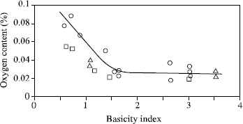
Figure 5.6. Relation between the transition temperature at 70 J and the oxygen content of submerged arc welds; from [TAY 75]
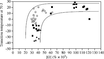
What is more, if the temperature change corresponding to a certain value of rupture energy (70 J in Figure 5.6) measured during impact tests on a great number of welds according to their oxygen contents, it appears that above 400 to 450 ppm of oxygen this temperature is always high. Conversely, at lower values a very great disparity in the results appears. This confirms the fact that oxygen content, an imperfect indicator of the inclusion rate, governs the ductile energy of rupture, which, for high rates, comes very close to the value selected here to characterize the transition. On the other hand, the very great scattering observed in Figure 5.6 for oxygen contents lower than 400-450 ppm shows that this factor is not determining because it is in fact the microstructure which governs the ductile/fragile transition.
The second property of a flux, fundamental on the metallurgical level, lies in the hydrogen content of the deposited metal which it controls. With regard to granular fluxes, what was stated previously for coated electrodes applies:
– there is no universal relation between flux humidity and diffusible hydrogen;
– for a given flux, two different relations exist between humidity and hydrogen depending on whether the moisture variation results from a variation in residual humidity after baking or from moisture pick-up;
– to achieve low hydrogen levels requires a selection of raw materials containing little water of crystallization and releasing this water at the lowest possible temperature;
– the use of mixed binders i.e. sodium, potassium, lithium makes it possible to minimize moisture pick-up;
– a rise in flux baking temperature makes it possible to lower the diffusible hydrogen content of the deposited metal.
However, we should not lose sight of the fact that a flux must satisfy requirements for operational weldability which often prove incompatible with the search for a very low hydrogen level. To preclude this difficulty, certain basic fluxes are not baked at very high temperature, they then contain carbonates which while breaking up in the vicinity of the arc make it possible to lower the partial hydrogen pressure in the gas cavity and thus reduce the transfer of hydrogen into the molten metal.
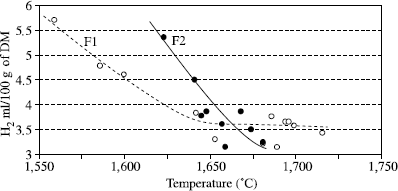
In the case of fused fluxes, the factors which influence the diffusible hydrogen content are fewer than with granular fluxes but even for a given flux formula, it is not possible to make the least correlation with the moisture content. This is owing to the fact that humidity measurements are conventionally taken at 950 or 1,000°C, whereas the preparation of fused fluxes involves taking the flux in its liquid state up to 1,500 or 1,600°C. The moisture measurement, such as it is practiced, cannot thus reveal water content still present in the flux because it is released only at a higher higher temperature than the manufacturing temperature of fused fluxes. In fact, for each flux formulation, a strict correlation between its manufacturing temperature and the content of diffusible hydrogen in the deposited metal is observed (see Figure 5.7).
A low diffusible hydrogen content is thus not necessarily associated with fused fluxes; conversely, the exposure of the flux to a humid atmosphere is of little consequence, which minimizes the precautions to be taken before its use (storage conditions or heating conditions, etc.).
Figure 5.7. Influence of manufacturing temperature on the diffusible hydrogen content of the metal deposited by two calcium-silicate fused fluxes
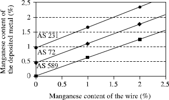
A final characteristic to take into account for fused as well as granular fluxes relates to the transfer of alloy elements in the arc. Indeed, the flux determines the arc atmosphere and thus the chemical exchanges which occur there: the analysis of the deposited metal is never the analysis of the wire used. Generally, we observe an enrichment in silicon while the manganese content can be above or below that of the wire depending on the flux used (see Figure 5.8). This does not constitute a quality standard but these chemical transfer characteristics, given by the supplier, must be taken into account before choosing the wire appropriate for the flux, or dictated by the properties sought for the weld.
5.3. Welding gases
5.3.1. Welding processes under a gas flux with an infusible electrode
TIG (tungsten inert gas) and plasma processes both use a tungsten electrode as a cathode. Since tungsten is a very oxidable material and, what is more, tungsten oxide sublimates at low temperature, the shielding gas for TIG and the plasmagenous gas for plasma welding can contain neither oxygen nor CO2. In addition, the nitrogen content must be maintained below 2% so as not to adversely affect the electrode’s lifespan, even when from a metallurgical perspective it is advantageous to have more (in the case of welding of duplex stainless steels for example).
Thus, leaving aside the rare and extremely expensive gases such as neon, xenon and krypton, the only gases usable in the mixtures associated with these processes are argon, helium, hydrogen and nitrogen, within the limit indicated before.
Argon and helium are neutral gases and can thus be used whatever materials are to be welded, but their respective physical characteristics confer on them specific effects when welding:
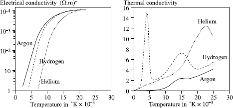
– argon has a much lower ionization potential than helium (15.7 and 24.5 eV respectively) and a much higher electric conductivity (see Figure 5.9). The result is that it is much easier to start an arc and to stabilize it under argon than under helium but also that an arc of given length is, for the same current, more powerful under helium than under argon (higher voltage);
– the thermal conductivity of helium is much greater than that of argon. Thus, with the same current, an arc under helium is more opened out than under argon, and leads to a lower heat gradient at the level of the parts to be assembled, promoting bead wetting.
Hydrogen is a diatomic gas at room temperature. When the temperature rises, it passes initially into an atomic state then to an ionized state, which explains the two thermal conductivity peaks of Figure 5.9, whereas the other gases show only the ionization peak. This characteristic has very important consequences for arc welding:
– the hydrogen molecule of the shielding gas absorbs energy by disintegrating around the periphery of the arc column, which lowers the temperature locally and causes arc constriction;
– the atomic hydrogen present in the arc will recombine while releasing some energy in the “cool” zones, i.e. at the level of the weld pool, etc.
Figure 5.9. Electric and thermal conductivities of various gases depending on the temperature; from [BOU 83]
The arc constriction increases the power density and consequently the penetration, as the recombination of the hydrogen atoms at the site of the weld pool thus improves the transfer of energy and thus the efficiency of the welding process (see Figure 5.10). As a corollary, for a given electric output and thickness, the combination of these two effects makes it possible to significantly increase the welding speeds in the TIG or plasma process by using an argon-hydrogen mixture rather than pure argon or argon-helium.
Figure 5.10. Influence of the shielding gas on penetration in TIG welding (316L steel: I = 200 A; distance of electrode to part = 2 mm; welding speed 20 cm/min
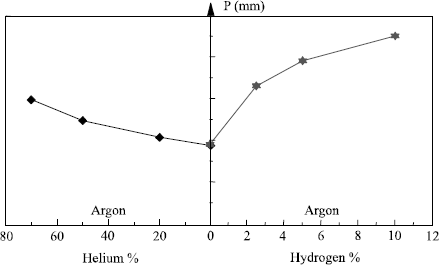
Thus, the basic gas in TIG or plasma welding is argon, but each time that it is possible, i.e. in the absence of adverse metallurgical effects, it will be beneficial to favor the use of argon-hydrogen mixtures. This is because they allow an increase in welding speed or pass thickness which, in both cases, leads to a significant improvement in productivity. The use of the ternary mixture Ar-He-H2 can further raise welding speed, with helium aiding the bead wetting.
Metallurgical incompatibility can result from the formation of porosities in the weld bead with alloys presenting an important variation in the solubility of hydrogen on solidification like aluminum alloys for example. It can also derive from the risk of cold cracking with ferritic steels when they are sufficiently “hardenable” to develop a non-ductile structure in the HAZ or the molten metal. This last risk must however be carefully calculated because the diffusible hydrogen content carried into the molten metal of course depends on the hydrogen content of the gas mixture used, but remains lower than 5 ml/100 g for a hydrogen content of 3% in argon. On the other hand we can, without disadvantage, use mixtures containing up to 5% of hydrogen to weld austenitic stainless steels or nickel alloys.
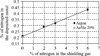
When a filler wire is used in TIG or plasma welding, it is introduced in front of the arc, just above the liquid bath. It is then molten at the periphery of the arc and the drops are incorporated one by one in the weld pool without being exposed to the very high temperatures reached in the center of the arc column. Consequently, there are few analytical differences between the deposited metal and the filler wire, the only notable variation relating to the loss of nitrogen during the welding of duplex and superduplex steels. The use of a welding gas containing nitrogen makes it possible to adjust the content in the deposited metal and to thus improve the corrosion resistance of the weld bead (see Figure 5.11).
Figure 5.11. Nitrogen content of the deposited metal as a function of the nitrogen content of the shielding gas (TIG welding); superduplex wire; nitrogen in the wire: 0.25%
5.3.2. Welding processes under a gas flux with a fusible electrode
The gas mixtures used in welding with fusible wire (GMAW) have an influence on arc stability, the mode of metal transfer from the wire to the weld pool and the bead shape. They also determine the chemical exchanges in the arc and consequently the analysis of the deposited metal with a given wire.
Operational aspects
Arc stability is dependent on the more or less easy extraction of electrons from the cathode in order to maintain the arc. However, in MIG/MAG welding, it is actually the parts to be assembled which form the cathode. This is why, each time it is metallurgically acceptable, oxidizing gas mixtures are used, so as to form a fine oxide coating just in front of the arc which aids thermo-electronic emission [JON 95].
The metal transfer can take various forms depending on the parameters used:
– with low welding currents, i.e. for low wire feed speeds, the metal transfer from the wire to the weld pool is performed by short-circuit (short arc mode). The arc periods are interrupted with periods during which the drop which was formed at the end of the wire comes into contact with the weld pool. During this phase, the arc dies out and the current greatly increases which, via electromagnetic forces, initially causes a striction of the molten metal at the upper part of the drop, then its detachment. The arc can then be restored and the process started again;
– with high currents (high wire feed speeds), the metal transfer takes place by axial pulverization (spray arc). The end of the wire takes the shape of a cone from the point of which fine droplets are ejected in the wire axis, which are then transfered towards the weld pool. The higher the current, the finer the droplets and the greater their speed;
– with intermediate currents, the transfer is known as globular. The drops which are formed at the end of the wire grow bigger until reaching a diameter significantly higher than that of the wire and are detached in an erratic way before the short-circuit occurs. This mode, which is relatively unstable, is the origin of much spattering.
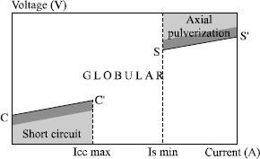
The welding current is thus a determining factor of the mode of transfer. Nevertheless, for a current compatible with transfer by short-circuit or by axial pulverization, it is possible to obtain a globular transfer by adjusting the voltage (very high voltage with low currents or very low voltage with high currents).
Generally, the various transfer fields can be represented in a diagram U = f (I), as in Figure 5.12.
In this figure, the points to be noted are the following:
– the current Icc max, which corresponds to the maximum at which a transfer by short-circuit is possible;
– the right segment CC′ which delimits the maximum voltage value permitting this type of transfer; in practice, welders regulate the voltage to a value slightly lower than this maximum (see shaded zone);
– the current Is min., which corresponds to the minimum at which transfer by axial pulverization can be achieved;
– the segment SS′ indicates the minimum voltage at which a transfer by axial pulverization is observed, welders generally working with a slightly higher value;
– the precise limits of these transfer fields in the diagram U = f (I) are characteristic of a given wire/gas combination. They change with the nature of the shielding gas but also with the wire diameter used: any addition of CO2 and/or oxygen in the argon increases the size of the globular field by decreasing Icc and by increasing Is (see Figure 5.13) so that it is no longer possible to obtain a metal transfer by axial pulverization as soon as the CO2 content exceeds 50% in the argon.
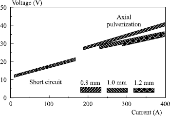
In addition, an increase in wire diameter causes an increase in current Is, Icc remaining practically unchanged (see Figure 5.14).
Figure 5.13. Influence of O2 and CO2 content in argon on the size of the globular field in MAG welding (wire ER 70S3; ϕ 1 mm; distance of contact tube to part, 15 mm)
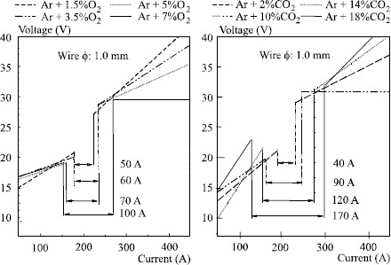
Figure 5.14. Influence of wire diameter on the transfer fields in MAG welding (wire ER 70S3; gas: Ar + 3% CO2{su+} 1% O2; distance contact tube and contact/part, 15 mm)
In addition to these three basic fields, a mode exists at very high currents when welds are made with a large gap from the contact tube to the part (>25 mm), where the transfer is rotary (rotating jet transfer or rotating spray) [LES 58, USC 93]. Beyond a certain value of welding current, the cone which is formed at the end of the wire electrode becomes sufficiently long and malleable to curve in on itself and rotate under the electromagnetic forces. The curve is more pronounced the higher the current is and can even reach 90°, so that the molten metal drops which are ejected according to the direction of the cone end then give rise to many spatters. This is undoubtedly the reason why this type of transfer has long been regarded as undesirable; nevertheless, as long as the curve remains slight, it can lead to an improvement in bead wetting and compactness because it is strongly dependent on the shape of the penetration.
The shape of the penetration is directly related to the mode of metal transfer. In short-circuit or globular mode, a lenticular penetration is observed which is explained simply from the laws of heat propagation from the surface. On the other hand, when the transfer is carried out by axial pulverization, the penetration becomes pointed. This is because the drops which are propelled at high speed in the wire axis cause a depression of the liquid bath at their impact point and impart a movement to it, which transfers heat towards the bead bottom. In this part of the bead, shaped like a glove finger, the solidification speed is much higher than in the remainder of the bead and when this is very deep, i.e. that at high welding currents, we often observe a lack of compactnesses such as blisters and shrinkage cavities are observed (see Figure 5.15). On the other hand, the rotating transfer mode generally leads to sound beads in spite of the very high currents employed, because the impact of the drops in the weld pool changes place permanently, so that round or even flat penetration is found, which does not imply high solidification speeds.
Figure 5.15. Morphology and compactness of beads created at high currents according to the mode of metal transfer: a) transfer by axial pulverization; b) rotating transfer

The various fields which we have just described correspond to natural evolutions in the metal transfer modes according to the current density in the wire electrode, the arc length (voltage) and its atmosphere; provided a simple voltage generator is used for welding. This causes some problems for the welder because these natural transfer modes are closely related to the energy employed which, in practice, cannot be selected independently of the welding position and the type of joint envisaged. Thus, a current corresponding to the axial pulverization mode cannot be employed to weld in vertical or overhead positions because the weld pool would be too bulky and would collapse. Thus, we must weld in the globular mode and accept the erratic transfer and the associated spatters, unless we reduce productivity considerably by lowering the current and welding in the short arc mode. To mitigate these disadvantages, and to a certain extent to dissociate the metal transfer mode from the current and the welding voltage, certain generators employ electronics which constantly control the current in a very fast and precise way, so that the transfer of the drops can be regulated and controlled even for average values of the welding current and voltage which would naturally incline us to the globular mode. This is called the pulsed mode. For each average current and thus wire feed speed, this mode is characterized by a base current and time value, a peak current and time value as well as the ascending and descending slopes. The peak current must be higher than the minimum current allowing axial pulverization (Is in Figure 5.12), the other parameters being programmed so that only one metal drop transfers from the wire towards the weld pool in each cycle. This leads to a perfectly stable mode, free from spatters — provided of course that programming the various pulsed mode parameters is well adapted to the wire/gas combination. Recall that each wire/gas combination has “natural” transfer characteristics which are intrinsic to it.
Generally, the same generators which are equipped with fast control electronics are also able to preserve the short-circuit transfer mode for average current values higher than Icc in Figure 5.12. This is particularly advantageous when we want to weld at high speed, because it is possible to utilize a linear energy adapted to the travel speed while preserving a very short arc, which is thus less likely to stall than the “natural” or pulsed arc corresponding to the same average current.
Chemical aspects
The analysis of a deposited metal is never identical to the analysis of a wire electrode in welding under a gas flow with a fusible wire, because during their transfer in the arc, the metal drops on the surface reach boiling point. Thus, the more volatile elements are vaporized more intensely than the others, which explains why they are found in great quantities in welding fumes but are less prevalent in the deposited metal than in the filler wire. Typically this is true of manganese in steels, magnesium in 5000 series alloys or zinc in brasses.
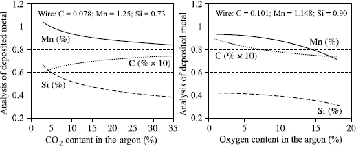
In addition to this fractional distillation and independent of the welding atmosphere, chemical reactions occur, especially at the level of the drops, when the shielding gas has some capacity for oxidation. The greater this oxidation capacity, the greater the analytical variations between the deposited metal and the wire, and the more oxidable elements (Si, Mn, Al, Ti, etc.) occur as slag on the surface of the beads (see Figure 5.16). At the same time, the oxygen content of the deposited metal and the inclusion rate increase.
Conventionally, the International Institute of Welding considers that the oxidation power of a shielding gas is equal to the sum of its oxygen content and half of its CO2 content (Doc. IIS XII-543-77). The two graphs in Figure 5.16 show that this approach is very approximate since the losses of manganese and silicon are much greater than the IIS suggest with its comparison of argon-oxygen mixtures and argon-CO2 mixtures. In addition, depending on the percentage of carbon in the wire and of CO2 in the shielding gas, there will be a carburizing or decarburizing effect in addition to its oxidizing effect. Thus, an argon mixture + 18% CO2 will be carburizing if the percentage of carbon in the wire is lower than 0.07% and decarburizing above that value; for the same reason, we should not have more than 1.5% of CO2 in the shielding gas if we hope to preserve the low carbon characteristic (<0.03%) of an austenitic stainless steel weld (Figure 5.17).
Figure 5.17. Influence of CO2 content in the shielding gas on the percentage of carbon in the deposited metal depending on the transfer mode (ER308LSi wire with C=0.18%)
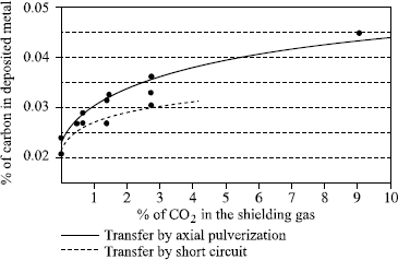
Figure 5.18. Influence of nitrogen content of the shielding gas on the nitrogen content in the deposited metal (MIG welding); superduplex wire (N = 0.24%); two transfer modes
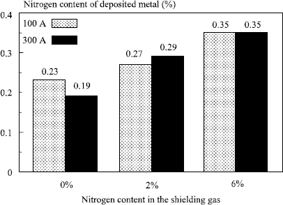
Thus, for GMA welding as for welding with a solid flux, the chemical characteristics of welds are not only related to the wire used but to the wire/flux combination. However, a difference exists. Whereas, depending on the solid flux used, the deposit can be more or less rich in alloying elements than the filler wire, it is generally less rich in welding with a gaseous flux except for carbon, as we have seen previously, and nitrogen, a certain quantity of which can be transferred into the deposited metal when nitrogen is present in the shielding gas (Figure 5.18).
5.4. Cored wires
5.4.1. Manufacturing processes
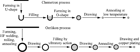
The cored wires marketed today are mainly manufactured according to one or other of the two processes presented in Figure 5.19.
To manufacture a wire according to Chemetron technology, we start from cold rolled strip iron small in size (about 13 × 1 mm) which is formed initially into a U. A homogenous mixture of the various constituent raw materials is then placed inside and shaped in an O, which is then drawn out to the required diameter. Annealing at low temperature is finally carried out so as to destroy the residual soap still present on the wire and to slightly oxidize its surface in order to confer a sufficient resistance to atmospheric corrosion.
The Oerlikon technology is more complex. It begins with the manufacture of a tube approximately 16 mm in diameter starting from hot rolled strip iron slightly more than 2 mm thick welded at high frequency then rolled to a diameter of about 13 mm. Softening is carried out by annealing, then the tube is drawn out to the filling diameter, which varies according to the manufacturing specifications.
Filling then takes place, the powder rising by vibration in tube sections of approximately 500 kg installed on a vibrating table. The filled tube is then drawn out into an intermediate diameter, at which stage it has to undergo recrystallization heat treatment before being drawn its final diameter, where it will be copper plated.
Thus, Oerlikon technology makes it possible to produce sealed filled coppered wires which resemble solid wires and are used as such. These cored wires are completely impervious to moisture pick-up and typically have diffusible hydrogen levels of about 2 to 3 ml/100 g of deposited metal. This is because chemical reactions occur inside the tube during the recrystallization annealing, releasing hydrogen, which escapes through the tubular sheath. However, this process implies a preliminary powder granulation by means of a silicate in order to avoid segregations at the time of the vibratory filling operation. Moreover, these granulated powders must be able to support the high temperatures associated with the recrystallization treatment applied to the tube without undesirable changes.
Such constraints do not exist with the Chemetron process. It is by no means necessary to granulate the powders or introduce a silicate which might have undesirable side-effects during welding, or even take into account a possible constituent decomposition during the heat treatment, which in this case is carried out at low temperature. Moreover, this technology makes it possible to produce wire with a higher filling rate (ratio of the powder weight to the wire weight) and as a result to obtain a greater deposition rate for a given welding current. On the other hand, as the Chemetron wires, are not welded, they are more or less liable to humidity pick-up depending on their content and so require more precautions during storage and use.
5.4.2. Types of cored wires
Both technologies make it possible to manufacture all varieties of cored wire designed to be used with a shielding gas, cored wires without gas only being produced today by means of the Chemetron technology.
Depending on the nature of the filling powders, three types of cored wires with shielding gas are to be found: rutile cored wires, basic cored wires and metal powder cored wires. Table 5.2 displays the principal components of these various types of cored wire, as well as the operational and metallurgical consequences which result from them. When it is compared to Table 5.1, relative to coated electrodes, we see great similarities between cored wires and electrodes of the same type, but also some important differences from the perspective of non-metallic components and the operational and metallurgical consequences.
In wires manufactured by Chemetron technology, we always add ionizing elements in order to help arc stability; it is not essential in the Oerlikon process, this role being played by the silicate used for the granulation of filling powders.
Unlike coated electrodes, cored wires with shielding gas do not systematically contain carbonates because, in this case, it is the shielding gas which prevents the contamination of the drops and the weld pool by atmospheric nitrogen and oxygen.
Rutile wires never contain organic elements such as cellulose or extrusion agents in the electrodes. Thus, for cored wire, the rutile or basic character has no impact on the diffusible hydrogen of the deposited metal.
More powerful deoxidizers, or deoxidizers added in greater quantity than in rutile electrodes, can be used in wires. This makes it possible to have formulae which associate good operational properties with oxygen contents of the deposited metal around 450 ppm, i.e. not very different from the basic products.
The current density is much greater when welding with cored wire than with coated electrodes (120 to 300 A for a wire 1.2 mm in diameter, compared to 80 to 120 A for an electrode with a diameter of 3.2 mm). This makes it possible to attain the axial pulverization mode of metal transfer with rutile wires and metal powder cored wires,. This mode leads to a very stable arc and the virtual absence of spatter.
Combining of the axial pulverization mode with the physical characteristics of certain rutile slags (melting point, viscosity and surface tension) imparts a much higher productivity to these wires than all the others wires, cored or solid, during out of position welding (+ 50% in vertical up welding for example); such a variation does not exist between rutile and basic electrodes.
If we consider the metallurgical potential of these various types of wire, the basic wires are the best, followed by metallic powder cored wires then rutile wires; on the other hand, precisely the opposite classification is reached on the basis of their operational quality with a very great advantage for rutile wires when it is a question of welding in all positions. This is why for about 15 years, developments have been primarily related to the improvement of metallurgical qualities in rutile wires by refining the microstructure of the weld metal employing the titanium/boron effect. These efforts have met with success, so that today basic wires are effectively used only for welding steels with a very high yield strength (≥690 MPa). The remainder of the market is divided between metal powder cored wires, valued in flat welding because they offer better performance than the other wires (absence of slag), and rutile wires when it is necessary to weld in all positions.
5.4.3. The titanium/boron effect in relation to rutile cored wires
This effect results from the presence of a very small quantity of boron (typically 20 to 60 ppm), which considerably delays the nucleation of proeutectoid ferrite at the austenitic grain boundaries while the weld bead cools. Thus, the transformation of austenite can occur primarily by intragranular acicular ferrite germination on inclusions, provided that these have the necessary characteristics and thus are present on the surface zones of titanium oxide.
When the complete chemical analysis of the weld metal is well balanced in manganese, and possibly nickel (so that its hardenability is optimal for the thermal cycle undergone by the weld), the proeutectoid ferrite network is reduced to a fine edging, and the remainder of austenite is transformed into acicular ferrite. If it is moreover possible to incorporate an addition of molybdenum, a synergistic boron/molybdenum effect is achieved which makes it possible to remove the proeutectoid ferrite network completely and to obtain a structure made up only of acicular ferrite, which possesses remarkable toughness properties.
5.5. Choice of welding products
From the preceding considerations, it is clear that the choice of a wire/flux combination, whether it is solid or gaseous, will have to take into account:
– the supplier data concerning the chemical and mechanical characteristics respectively determined on a weld pad and an all weld metal deposit,
– the joint shape, the thickness and the chemical nature of the base metal.
The supplier catalog indicates the chemical and mechanical characteristics of deposits carried out under standardized conditions with great precision.
These standards (EN, AWS, etc.) indicate in a more or less precise way the welding parameters (U, I, Ws), the temperatures between passes and possibly even the pre-heating temperature, the pass distribution (generally two passes per layer) and the position of the various specimens necessary for characterization in the all weld metal deposit.
This type of information is absolutely essential to check product consistency but, taking into account all that has been said before, it is clear that these data are not necessarily representative of what will be obtained during the execution of a real joint for which the thermal welding cycle and/or the dilution rate of the base metal can bear no relation to the standardized conditions.
This is why welding product suppliers generally publish data sheets relative to their products which, in addition to the characteristics obtained under the standardized conditions, give results on joints produced under various conditions (heat input, dilution rates, etc.) and with various steels. They also provide additional details specific to each product, such as:
– the field of usable parameters,
– the deposit rate according to the current,
– the chemical transfer graphs,
– the behavior with respect to moisture pick-up,
– the granulometric distribution (for fluxes in submerged arc).
It is by starting from these data sheets and by applying metallurgical reasoning that we will be able to choose the products appropriate to achieving the goals imposed by the construction specifications.
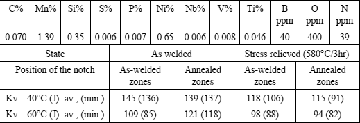
When high thicknesses are welded, the dilution ratio is low except in the root zone, but that is frequently gouged before welding the second side of the joint. In this case, we can use the catalog data to choose the products best adapted to the mechanical properties desired or, if the welding conditions considered are very different from the standardized conditions in terms of the thermal welding cycles, we can resort to the data sheets. Moreover, as this type of joint frequently undergoes a stress relieving treatment after welding, the choice of welding products will have to take account of this eventuality, as the weld metal characteristics can be significantly modified during this treatment1.
For welds involving only a small number of passes, the mechanical properties indicated in the supplier catalog are not of any use, since the analysis of the weld metal can be very different from that of the metal deposited by the products. In this case, the choice of welding products can only come from metallurgical reasoning based on the thermal cycle evaluated using the IRSID graph, the estimated dilution rate and the real analysis of the base metal (and not of the standard, which is far too vague from this perspective). On the basis of the thermal cycle, we can deduce the chemical analysis of the weld metal to aim for, depending on the properties desired, then calculate the analysis of the metal to be deposited. We also take into consideration the actual analysis of the plates to be welded and the rate of dilution so as to choose the wire/flux combination which will make it possible to achieve the desired result.
5.6. Welding products and the welder’s environment
Welding is at the origin of many harmful effects (UV radiation, noise, fumes, spatters, etc.) which of necessity entail the use of individual and collective protective gear in order to preserve the health of the welders or other personnel working in the vicinity. However, it is not always easy to guarantee the absolute effectiveness of this equipment whatever the localization of the welding, so any reduction in these harmful effects at the source can only have a positive impact on working conditions. This objective has become a major concern in the development of welding consumables and welding procedures and even if there is still a lot of progress to be made, it is now possible to considerably reduce some of these harmful effects.
5.6.1. Coated electrodes
The quantity of fumes emitted during welding with a coated electrode depends on the nature of the coating and the electric output employed. This is what Figure 5.20 illustrates for various diameters of two rutile and two basic electrodes of different grades. These results were obtained by using, for each electrode, the average current recommended by the manufacturer for the diameter considered. However, it should be borne in mind that fume emission can be doubled when the welding intensity is varied from the minimum to the maximum application field for a particular diameter. All in all, it can be seen that rutile electrodes have a fume emission rate ranging between 0.8% and 1% of the deposited metal, while for basic electrodes this rate is between 1.5% and 2%.
Figure 5.20. Fume emission rate of various electrode types and diameters depending on the arc power: rutile 6,013 and 7,024; basic 7,016 and 7,018

In the case of electrodes baked at low temperature (rutile electrodes), the fume emission rate increases with the potential hydrogen content, i.e. hydrogen coming from residual humidity after baking but also from all the organic materials of the coating. On the other hand, for electrodes baked at high temperature (basic and stainless), the fume emission rate is an increasing function of the sodium and potassium content of the coating. Thus, by removing all the components containing these elements from the coating, and by replacing them with lithium compounds, it is possible to halve the quantity of fumes emitted. Applying this formulation to stainless electrodes has the additional advantage of considerably decreasing fume toxicity. Indeed, fumes from traditional stainless electrodes contain approximately 4% of hexavalent chromium, which has a toxicity index 100 times higher than standard fumes and 10 times higher than chromium in a trivalent state (Oel CrVI: 0.05 mg/m3; Oel CrIII: 0.50 mg/m3; standard fumes Oel: 5 mg/m3). However, it proves that the replacement of sodium and potassium compounds by lithium compounds makes it possible to lower the content of CrVI in fumes to less than 1% so that fumes from these electrodes for stainless steels are no longer toxic than those of non-alloyed electrodes (see Figure 5.21).
Figure 5.21. Comparison of fume emission rates and hexavalent chromium between standard stainless electrodes and electrodes with lithium
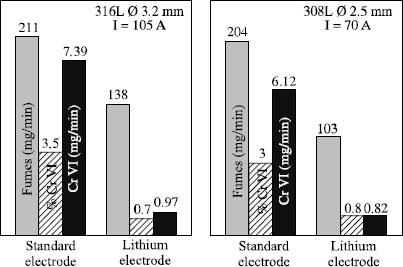
Today, the cost premiums associated with these formulation developments is considered to be prohibitive in the case of the traditional basic electrodes. However, it is acceptable for the stainless steels because of the much higher price of the cores of these electrodes. They are now on the market.
5.6.2. Gas mixtures for TIG welding
In TIG welding, fumes and spatters are non-existent but there is the problem of ozone formation during the welding of stainless steels and still more in welding light alloys.
Ozone results from the action of ultraviolet radiation, which “breaks” the surrounding oxygen molecules. The single oxygen atoms thus formed (O) will be able to react with other oxygen molecules (O2) and form ozone molecules (O3) whose toxicity is recognized. In fact, in UV radiation, emissions in the spectral band 130 to 180 nm are particularly liable to form these single atoms.
Figure 5.22. Influence of shielding gas type on the quantity of ozone formed in austenitic stainless steel TIG welding
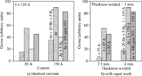
Figure 5.23. Influence of shielding gas type on the quantity of ozone formed in light alloy (alloy 5086) AC TIG welding
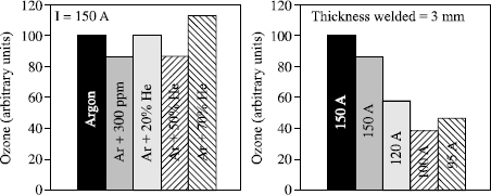
The radiation spectrum emitted by the arc depends on the energy employed and the chemical elements present. This is why the quantity of ozone formed increases with arc power (U × I) and, with identical power and shielding gases, more ozone is formed when we weld light alloys than stainless steels.
If the aim is to reduce the quantity of ozone which will diffuse into the atmosphere surrounding the welder, several solutions exist:
– minimize the radiation in the spectral band 130 to 180 nm. This can be achieved by replacing argon with helium as far as possible in the shielding gas;
– minimize the energy employed to produce any given joint. This can be achieved by modifying the process: TIG double flux or plasma lead to a deeper penetration than a TIG process with identical energy and thus make it possible to reduce the welding energy required to produce a given joint. It can also be achieved by using a shielding gas containing helium and/or hydrogen which, by modifying the arc morphology and by increasing the voltage with identical arc length, significantly improves the performance of the TIG process;
– introduce gas molecules into the shielding gas which are very reactive with respect to ozone and will cause its destruction (hydrogen or nitrous oxide NO).
Figures 5.22 and 5.23 illustrate the advantages to be gained from these various actions. They show that wherever possible it is found to be beneficial to use argonhelium-hydrogen ternary mixtures which combine the various effects. However, the mixture must be designed to take into account on one hand operational aspects (too high a content of helium and/or of hydrogen can pose problems for out of position welding) and on the other hand, of the metallurgy which leads us to reject, for example, the use of hydrogen for welding light alloys to preserve weld compactness. Finally, we should also note that certain welding equipment does not allow good arc stability with very high helium content. This explains the increase of the ozone content with the argon mixture + 70% helium in Figure 5.23.
5.6.3. Gas mixtures for GMAW
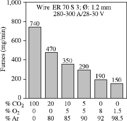
Apart from UV radiation, the emission of fumes is the principal harmful effect associated with GMA welding. As a first approximation, this increases in line with the oxidation power of the shielding gas (see Figure 5.24) but fumes and spatters are also closely linked to the metal transfer mode.
When welds are made with a current which produces transfer by axial pulverization for the wire/gas combination used, the fume emission rate and projections decrease when we increase the voltage until a stable transfer by axial pulverization is achieved. Beyond this value, an increase in voltage will not modify the metal transfer but does cause a simple lengthening of the arc, which in turn causes an increase in the volatilization of the metallic elements and, consequently, in the fume emission rate (see Figure 5.25).
This is a very general process, as shown in Figure 5.26 where fume emission rates relative to three gas mixtures in various welding conditions are compared. In this same figure, we can also see that the minimal emission values decrease when the oxidation power of the shielding gas decreases. It is also seen that specific comparisons with constant electric parameters can lead to inverse classifications of shielding gases, as identical electrical parameters do not correspond to similar operational point locations compared to the transfer curves characteristic of each gas.
Figure 5.25. Relations between fume emission rate, spatters and transfer graph. Wire: ER70S6 1.2 mm; gas mixture: Ar + 3% CO2 + 1% O2; distance of contact tube to part: 20 mm
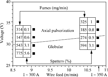
Figure 5.26. Comparison of the fume emission rate of three gas mixtures according to the voltage for two welding currents. Wire: ER70S6 ϕ 1.2 mm
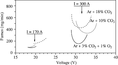
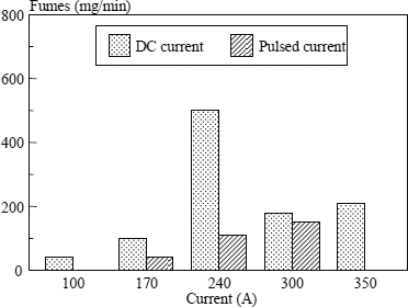
In practice, if we wish to reduce the fume emission rate, it will always be beneficial to use the least oxidizing shielding gas compatible with operating requirements. From this perspective, a mixture Ar + 3% CO2 + 1% O2 seems to us an excellent compromise for the welding of ferritic steels, and even more so as this mixture is perfectly adapted to pulsed welding. This will enable us to regularize the metal transfer but also to considerably reduce spatters and fume emissions when we are obliged to use parameters which correspond to globular transfer if a DC current is used (see Figure 5.27).
Figure 5.27. Comparison of fume emission rate between DC current and pulsed current. Wire: ER70S3 ϕ 1.2 mm; gas: Ar + 3% CO2 + 1% O2
5.6.4. Cored wires
The use of cored wire seems to be developing to the detriment of coated electrodes. However, although these products do not generate significantly longer fume emissions than electrodes when we view the results of the quantity of deposited metal, their greater productivity leads to an emission rate per unit of time which sometimes can constitute an impediment to their use.
The operational qualities of a cored wire are partly related to the shielding gas used but also to the nature of the “ingredients” which constitute the filling. Compared to solid wires, there thus exists an additional degree of freedom which makes it possible to consider the development of cored wire/gas combinations whose use would not generate CO. The quantity of CO formed being in direct relationship with the CO2 content of the shielding gas, it is necessary to adapt the wire formulations so that they have the necessary operational qualities with a gas containing no CO2. In addition, to minimize fume emissions, the gas must be the least oxidizing possible.
Today, it is not only metal cored wires that exist but also rutile wires designed to function with an Ar + 3.5% O2 mixture. Furthermore, as a means of minimizing CO emission, they can reduce fume emissions by about 50% compared to a standard wire used with an Ar + 18% or 25% CO2 mixture.
5.7. Bibliography
[BOU 83] BOURDIN E., FAUCHAIS P., BOULOS M., “Transient heat conduction under plasma conduction”, Int. J. Heat Mass Transfer, vol. 26, no. 4, p. 567-582, 1983.
[DIC 88] DICKEHUT G., RUGE J., “Method for predicting the content of diffusible hydrogen in the weld metal under the influence of atmospheric moisture”, Schweissen und Schneiden 40, no. 5, p. 238-241, May 1988.
[EAG 78] EAGAR T.W., “Sources of weld metal oxygen contamination during submerged arc welding”, Welding Journal, p. 76s-80s, March 1978.
[GAS 86] GASPARD-ANGÉLI A., BONNET C., “How to optimize the properties of the longitudinal welds of pipes using a fused flux”, Proceedings of the 3rd Intern. Conf., Welding and Performance of Pipelines, London, 18-21 November 1986.
[JON 95] JÖNSSON P.G., MURPHY A.B., SZEKELY J., “The influence of oxygen additions on argon-shielded gas metal arc welding processes”, Welding Journal, p. 48-58, February 1995.
[LED 92] LEDUEY B., BONNET C., DAMAGNEZ P., “Principes d’évolution des électrodes enrobées pour réduire l’hydrogène diffusible”, Soudage et Techniques Connexes, p. 15-19, July-August 1992.
[LES 58] LESNEWICH A., “Effect of shielding gas composition on metal transfer phenomena in high current GMA Welding. Part II — Control of metal transfer”, Welding Journal, p. 418s-425s, September 1958.
[TAY 75] TAYLOR L.G., FARRAR R.A., “Metallurgical aspects of the mechanical properties of submerged-arc weld metal”, Welding and Metal Fabrication, p. 305-310, May 1975.
[TUL 69] TULIANI S., BONISZEWSKI T., EATON N.F., “Notch toughness of commercial submerged-arc weld metal”, Welding and Metal Fabrication, p. 327-339, August 1969.
[USH 93] USHIO M., IKEUCHI K., TANAKA M., SETO T., “Effect of shielding gas composition on metal transfer phenomena in high current GMA welding”, Trans JWRI, vol. 22, no. 1, p. 7, 1993.
1 Chapter written by Christian BONNET.
1 The aim of a stress relieving treatment is to lower the internal stresses which arise due to multiple and non-uniform heatings which is a characteristic of welding. Its principle lies in reducing the yield strength of materials while raising the temperature: in a given structure, there cannot be internal stresses higher than the yield strength because if that were the case, it would lead to deformations which would continue until the stresses had been lowered to their yield strength. The stress relieving treatment then consists of heating to a temperature for which the yield strength of the metal under consideration is sufficiently low (580/600°C for most steels) such that the deformations occur and relieve the stresses.
However, in addition to this stress relief phenomenon, the treatment can cause some useful metallurgical reactions (tempering of out of balance structures, softening of hardened zones, etc.) but sometimes very damaging ones from the point of view of toughness (carbide, nitride or carbonitride hardening precipitations; temper-embrittlement developing during cooling after the relieving stage, etc.). The scale of these harmful secondary phenomena greatly depends on the nature of the products used and so it is essential when choosing products for a given structure to take into account the existence or on the contrary the absence of such a treatment during manufacture.
