Chapter 12
Welding Stainless Steels 1
12.1. Definitions
The definition from The Concise Oxford Dictionary, “stainless: a kind of chromium-steel alloy immune to rusting and corrosion”, is not a particularly apt description for these metals.
A better definition is given by the following:
– a steel is known as stainless if, in ambient air, it is covered naturally and quasi-instantaneously with a very fine layer of impermeable chromium oxide due to atmospheric agents in the environment,
– the stainless steel is then known as passive;
– a steel is known as stainless if it contains at least 12% chromium (10.5% according to the standards).
12.2. Principal stainless steel families
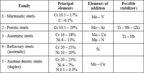
Stainless steels can be classified in five main groups according to their composition and their metallurgical structure (see Table 12.1).
Transitional structures or analytical particularities give rise to sub groups placed between the main groups or added to them. Specifically these tend to be martensoferritic steels and martensitic or austenitic steels with precipitation hardening.
All these stainless steels can be derived from the basic austenitic steel AISI 304 (EN 1.4301) by the addition or subtraction of one or more elements to achieve a particular property in preference to another. This is clearly described in Figure 12.1 (an American classification).
12.3. Metallurgical structures
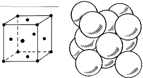
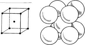
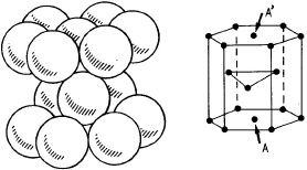
Stainless steels present three principal structures from which they draw their name, as well as a fourth, not very stable but important, in particular for the phenomena of cold hardening.
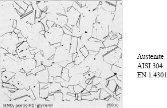
– Austenite:
– face-centered cubic structure (FCC),
– non-magnetic,
– soft but extremely work-hardenable,
– very malleable and workable.
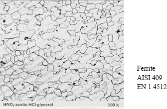
– Ferrite:
– body-centered cubic (BCC) structure,
– ferromagnetic,
– soft and not very work-hardenable,
– malleable and moderately workable.
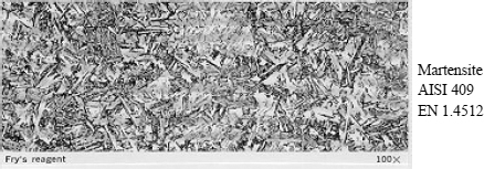
– Martensite:
– body-centered cubic (BCC) structure,
– ferromagnetic,
– hard and brittle,
– not very malleable and unworkable.
– The hexagonal compact structure
– densest of the structures,
– transformation during cold work hardening from austenite γ to martensite α‘γ→∈→ α’.
Some micrographical images of the principal structures are presented in Figures 12.5, 12.6 and 12.7.
12.4. Constitution diagrams
12.4.1. Introduction
Man has always sought to predict the future. It is not always easy, but industry lends itself relatively well to this idea.
Welders wish in particular to predict the immediate or eventual risks which they (or their customers) will encounter at the time of assembly. They wish to know what is the best procedure to use and, if a filler is necessary, which one, metallurgically speaking, is the best.
On the basis of the alpha gene effect (favoring ferrite formation) and gamma gene effect (supporting austenite formation), diagrams have been devised with the aim of predicting the metal’s structure in its as welded state. These are prediction diagrams.
These diagrams have been established then modified and improved over time by examination of the micrographic structures of the molten zones in their as welded state.
Regression calculations have enabled various authors to define calculation formulas of Cr (chromium) and Ni (nickel) equivalents which are employed as the alpha gene and gamma gene effect coefficients of the various elements taken into account and which are used as coordinates for the diagrams.
12.4.2. Calculation of the equivalent formulae
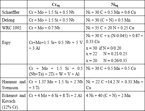
Without prejudice to other formulae which have been and are still used, the principal Cr and Ni equivalent formula are presented in Table 12.2.
The first, Schaeffler, tried to predict the welding of stainless steels.
Thus, he was the first to establish formulas giving Creq and Nieq for the grades of stainless steels existing at that time.
In the 1960s, Delong integrated the gamma gene effect of nitrogen, which he considered as powerful as that of carbon.
In the 1970s, Espy, taking up Schaeffler’s calculations and extending their scope of application (grades with nitrogen, manganese and duplex inter alia), discovered and introduced:
– the significant alpha gene effect of vanadium and aluminum,
– the gamma gene effect but weighted by its nitrogen content,
– the constant manganese gamma gene effect.
At the end of the 1980s, the Welding Research Council established simplified formulae by:
– removing the alpha gene effects of Si (questionable for steels whose Si content can vary from 0.1 to 2%) V, Al, Ti and others;
– removing the constant Mn gamma gene effect, but by integrating it in the diagram,
– fixing the C and N gamma gene effect, while modifying them slightly.
The other formulae quoted in the table give are associated with very particular applications which will be discussed later.
12.4.3. Constitution diagrams
Various diagrams are presented in the following pages. They are used to predict the structure of the as welded molten metal.
– Schaeffler diagram
This is the best known and most widely used diagram by pressure vessels manufacturers, in particular for heterogenous welds.
This diagram has one major disadvantage in that it is not suited to grades with high manganese and/or high nitrogen content.
In the case of completely homogenous welds in austenitic stainless steel or when the analysis of the molten metal is known, the calculation of the ferrite content in the as welded metal can be made by Séférian’s formula, which is derived from the Schaeffler diagram:
% ferrite = 3 (Creq − 0.93 Nieq − 6.7)
– Delong diagram
Taking account of nitrogen content as a gamma gene effect led W. Delong to construe a different diagram from that of Schaeffler.
Commonly used in nuclear stainless pressure vessel construction, this diagram presents two major disadvantages:
– its limited application field makes it unusable for heterogenous weldings in particular,
– it cannot be applied to grades with high manganese and/or nitrogen content.
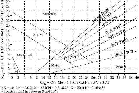
– Espy diagram
This is the Schaeffler diagram refined for the equivalent Cr and Ni calculation formulae.
This diagram is particularly well adapted to stainless grades with high manganese and/or nitrogen content and to duplex steels.
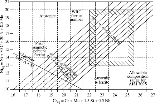
– WRC92 diagram
This is the simplest, but unfortunately the least precise diagram:
– a reduced number of elements for the Creq and Nieq calculation,
– a limited application field, making it impractical for heterogenous welds.
Originally, this diagram was graduated only in FN (ferrite number or ferrite index) which was not transposable linearly to % ferrite content, which made it rather impractical. This defect was corrected and the graduation is now made both in FN and ferrite %.
– Comparison of the various diagrams
The advantages and disadvantages of the various diagrams are summarized in Table 12.3.
Table 12.3. Comparison of the various diagrams
| Diagram | Advantages | Disadvantages |
| Schaeffler | - heterogenous welding - scope of application | - not for high Mn (>2%) - not for high N (>0.10%) - not very precise (ferrite >20%) |
| Delong | - approved by ASME - ferrite % and FN | - limited field Creq >16 Nieq >10 ferrite <20% - not for high Mn (>2%) - not for high N (>0.10%) |
| Espy | - heterogenous welding - scope of application - many elements - high Mn and/or N | - not very precise (ferrite >20%) |
| WRC 92 | - standardized in Europe (EN standard…) - simplified calculation | - few elements - limited field Creq>17 Nieq >9 |
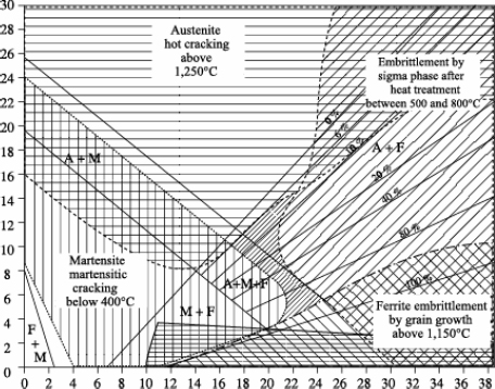
– Bystram diagrams
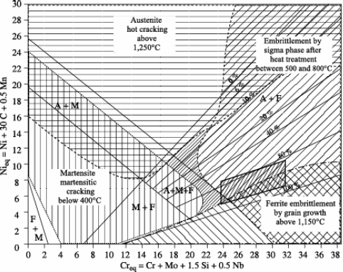
Brystram diagrams are not constitution diagrams, but, when superimposed on them, they allow the identification of four major risk zones:
– risk of hot cracking,
– risk of sigma phase formation,
– risk of cold cracking,
– risk of grain growth.
The complete diagram represented in Figure 12.12 shows that the zero risk field is relatively reduced and that various stainless steels are susceptible to one or other of the above risks (even two at the same time).
12.5. Welding ferritic stainless steels
12.5.1. Introduction
The family of ferritic stainless steels covers an important range of chemical compositions, based in general on the ternary diagram Fe-Cr-C. These steels contain a minimum of 11.5% chromium and a maximum of 0.1% carbon.
The properties of these steels are primarily based on the chromium content associated with a corrosion resistance.
As far as welding is concerned, ferritic stainless steels are weldable subject to care being taken to mitigate certain critical properties.
12.5.2. Risks incurred in welding
Ferritic stainless steels contain in practise from 11.5 to 29% of chromium, a generally low carbon content and other different alloying elements (Mo for corrosion performance, Al for temperature behavior, Ti and/or Nb for stabilization).
The position of stainless steels on a Schaeffler-Bystram diagram reveals the risks incurred in welding these steels:
– risk of cold cracking for semi-ferritic steels, particularly with a strong hydrogen sensitivity,
– risk of forming intermetallic compounds (phase σ), at least for steels with very high chromium equivalent. Taking into account the speed of the thermal cycles, the formation of phase ó is not normally expected during the welding operation itself,
– risk of grain growth, which is all the more likely the higher the welding energy is.
Lastly, it is important to emphasize a very important point about the metallurgy of ferritic stainless steels: the very low solubility of carbon and nitrogen, imposing for many welding applications in particular, stabilization by titanium and/or niobium, whose mechanism and other effects are presented hereafter.
12.5.3. Stabilization
The majority of these risks are removed or significantly decreased by the use of stabilized steel types.
The stabilizing elements (Ti, Nb) are elements whose carbides and nitrides are formed in preference to those of chromium during heat treatments. They are used to trap carbon and nitrogen.
Stabilization plays several roles. Indeed, we know that: carbon and nitrogen are practically insoluble in ferrite; precipitated chromium carbides and nitrides are instigators of intergranular corrosion by chromium impoverishment of the surrounding matrix; post-operative heat treatments are not always easy or feasible; grain growth of the ferritic structure is not recoverable by heat treatment; the use of stabilized Ti or Nb grades, or even bistabilized Ti + Nb types is strongly advised as soon as a welding operation is envisaged.
The effects of stabilization are numerous and can be summarized as follows:
– stabilization by titanium is characterized by titanium nitride precipitation in the liquid state, (solidification occurs around these TiN germs, creating favorable conditions in the molten zone for obtaining an equiaxial structure giving rise to a good impact strength), and by the precipitation of titanium carbides in the solid state around 1,050°C, around titanium nitrides;
– stabilization by niobium is characterized by niobium carbo-nitride precipitation in the solid state around 1,150/1,200°C, and possible precipitation between 600 and 950°C of intermetallic Fe2Nb with the effect of blocking grains favorable to creep behavior at high temperature;
– niobium or titanium carbo-nitrides decrease sensitivity to ferrite grain growth;
– titanium and niobium, by “trapping” the strong gamma gene elements, carbon and nitrogen, tend to stabilize ferrite, therefore avoiding the formation of martensite.
The stabilization formulas most generally selected are:
– Ti% >0.2 + 4 (C% + N%),
– Nb% >0.15 + 7 (C% + N%).
12.5.4. Risks of embrittlement
There are four risks of ferritic stainless steel embrittlement:
– embrittlement at 475°C,
– sigma phase,
– embrittlement at high temperature,
– sensitivity to the notch effect.
Embrittlement at 475°C
Ferritic stainless steels are sensitive to embrittlement at 475°C (between 400 and 600°C) due to poor chromium miscibility (and also molybdenum) in a Fe-Cr alloy involving the formation of a phase α′ rich in chromium (30%) and in molybdenum, a hard and brittle phase.
This phase is formed after very long periods in its field of stability. It is very seldom observed. Embrittlement at 475°C is not to be feared after a welding operation.
Sigma phase
The sigma phase is an intermetallic compound appearing in the iron-chromium system. This is why we mention it in this chapter, although it does not play a significant role in the welding of ferritic and semi-ferritic steels. The sigma phase is hard and brittle, and its appearance in welds can cause a true brittleness appearing even in the absence of a notch and which does not disappear with a moderate rise in temperature.
However, welds of ferritic and semi-ferritic steels having a low impact strength at room temperature, the importance of the formation of the sigma phase in these welds remains secondary.
The sigma phase has a composition based on a chromium content of 45%, and it can occur by prolonged treatment above 550°C in iron-chromium type alloys containing more than around 22% chromium.
Embrittlement at high temperature
Embrittlement due to maintaining a high temperature for a prolonged period is influenced by many factors, analytical as well as structural: chromium content and interstitial compounds, grain size, nature and distribution of precipitates. The welding operation does not generate embrittlement at high temperature.
Sensitivity to the notch effect
Semi-ferritic stainless steels low in chromium (Cr <15%) are not sensitive to the notch effect.
On the other hand, for steels containing more than 15% chromium, the sensitivity is dependent on interstitial compounds (C + N) content and increases with the chromium content.
The only means of decreasing this sensitivity is to control the C + N content, either by maintaining them at a very low level (be careful of grain growth) or by trapping them with a stabilizing element (Ti, Nb).
12.5.5. Filler products
Filler products are generally composed of austenitic stainless steel. However, it is important to note the availability of ferritic filler product grades which enable the formation of homogenous welds which has a significant advantage with regard to their performance in coping with a possible deformation.
The choice of filler product is made according to the base metals: the filler must be more alloyed than the noblest of the base materials to compensate for the losses in welding and in respect to the constitution diagrams.
The filler products are standardized:
– AWS standard:
– S.F.A. 5.4 — Electrodes,
– S.F.A. 5.9 — Bare wire,
– S.F.A. 5.22 — Filled wire;
– European standard:
– NF EN 1600 — Electrodes,
– NF EN 12072 — Bare wire,
– NF EN 12073 — Filled wire.
12.5.6. Shielding gases
Knowing that H2 and N2 are out of the question and CO2 not recommended (less than 3%), the shielding gases usable for welding ferritic stainless steels are set out in Table 12.5.
| Procedures | TIG | MIG |
| Primary gas | Ar | Ar + O2 (<3%) |
| Doping gas | He (<20%) | He (<20%) |
12.5.7. Summary: partial conclusion
Ferritic stainless steels are weldable without pre-heating or post-heating by respecting the following advice set out in Table 12.6.
| Advice | To combat |
| Stabilized steel grades | Corrosion Grain growth Embrittlement at high temperature Notch sensitivity |
| Stability of ferrite | % of martensite in semi-ferritics |
| Low welding energy | Grain growth Embrittlement |
 | Cold cracking Corrosion |
| CO2 inadvisable |  |
12.6. Welding of martensitic stainless steels
12.6.1. Introduction
The family of martensitic stainless steels comprises steels which combine a raised level of hardness with certain level of corrosion behavior (thanks to their chromium content), comparable with that of treated alloyed steels, and which can be produced by martensitic hardening.
This family generally includes certain structural hardening steels, whose low carbon martensite is relatively soft, but whose characteristics can be significantly increased by tempering treatments at average temperatures (from 500 to 750°C) judiciously selected to ensure the precipitation of hardening intermetallic compounds.
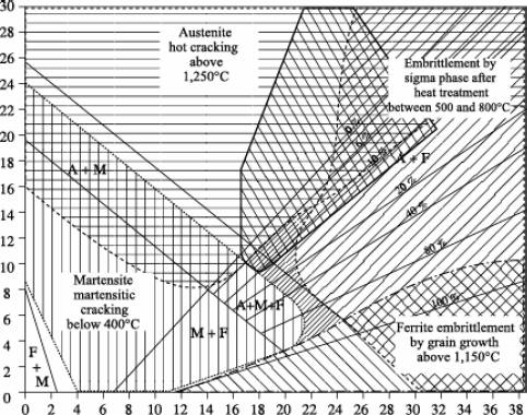
The positioning of martensitic stainless steels and those with structural hardening is schematized in the Schaeffler-Bystram diagram in Figure 12.14.
Figure 12.14. Schaeffer-Bystram diagram of martensitic stainless steels and those with structural hardening
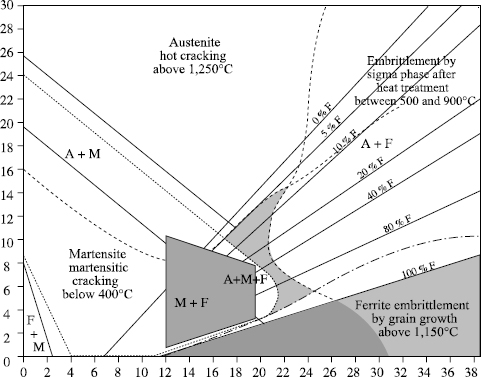
Martensitic stainless steels have a similar behavior with regard to welding to that of heat treated alloyed steels with an equivalent carbon percentage, and will thus be treated in a similar way.
12.6.2. List of martensitic stainless steels
A non-exhaustive list of the principal martensitic stainless steels and precipitation hardened steels taken from the EN 10.088-2 standard is presented in Table 12.7 below.
Table 12.7. Extract from the EN 10.088-2 standard
| X12Cr13 X12CrS13 X20Cr13 X30Cr13 *X29CrS13 X39Cr13 X46Cr13 | S = 0.15/0.35 S = 0.15/0.35 |
| X50CrMoV15 X70CrMo15 *X14CrMoS17 X39CrMo17-1 X10⁵CrMo17 X90CrMoV18 | V = 0.10/0.20 Mo = 0.40/0.80 S = 0.15/0.35; Mo = 0.20/0.60 Mo = 0.40/0.80 Mo = 0.90/1.30; V = 0.07/0.12 |
| X17CrNi16-2 X3CrNiMo13-4 X4CrNiMo16-5-1 | Mo = 0.30/0.70 |
| X5CrNiCuNb16-4 X7CrNiAl17-7 X8CrNiMoAl15-7-2 X5CrNiMoCuNb14-5 | Cu = 3.00/5.00; Nb = 5xC/0.45 Al = 0.70/1.50 Al = 0.70/1.50 Mo 1.20/2.00; Cu = 1.20/2.00; Nb = 0.15/0.60 |
12.6.3. Effect of the elements C, Cr and Ni on the γ loop
Martensitic stainless steels are characterized by the γ→α′ transformation which occurs without diffusion at low temperature (≤ 400°C), between MS and MF.
The grades concerned can be richer in Cr because the greater the extent of gamma gene elements such as C and Ni, the more stable the ã field at high temperature.
12.6.4. Metallurgical weldabiity of martensitic stainless steels
In the Schaeffler-Bystram diagram, these steel types are situated to the right of the martensite range, i.e. with sufficiently high Cr content (equal to or higher than 12%) to ensure a good corrosion resistance in relatively unaggressive environments. In the welds (MZ and HAZ in the immediate vicinity of the MZ), the rapid cooling starting from temperatures above the monophase ã field can favor the presence of ä ferrite at room temperature. In these zones, the structure will be made up of “fresh” martensite (as quenched state), and possibly of ä ferrite and also of residual austenite for the most alloyed grades. Some as hardened martensite will also be present in the HAZ of welds with austenitic filler. This martensite can be sensitive to cold cracking (hydrogen embrittlement with possibly differed rupture) and all the more so the higher the carbon percentage is (hard martensite), the more hydrogen is present, and the higher the thermal stresses. It is thus, in general, essential to pre-heat and post-heat the materials with T <MS, but close to MF to limit the stresses due to the phase change, to carry out a slight stress relief of the martensite immediately after its formation and to operate in a temperature range where hydrogen does not have a tendency to segregate in the former ã joints. Then it is necessary to relieve the weld stress in a temperature range equivalent to that used for the tempering of these grades (approximately 550 to 750°C according to the grades and the desired level of hardness). The stress level must also be limited by slow cooling and heating rates, especially for heavy parts, and also by a component design which avoids the concentration of stresses around the weld.
In the case of a weld with austenitic filler (308L, 309L, etc), the stress relief treatment of α′ is not possible because it would cause diffusion of the carbon of α′ towards γ and a reduction in corrosion resistance of γ by chromium intergranular carbide precipitation (sensitizing). Stress relief at around 250°C of the martensitic HAZ is possible.
The welding of high carbon or resulfurized grades is not advisable, whereas that of low carbon steel types (C <0.05%) can be practiced without pre-heating and post-heating, in particular for low carbon, highly alloyed (Ni, Mo, etc.) grades, which have a MF close to room temperature. For products which allow it, it is possible to carry out after welding, an austenitization followed by a hardening, which, in the particular case of grades with precipitation hardening in heavy products, makes it possible to obtain mechanical characteristics in the molten zone and corrosion resistance comparable with those of the forged product. The welding process can have a significant influence on ductility/impact strength properties, in particular by introducing elements which affect these properties, such as oxygen brought in by the welding operation on the coated electrode. Whereas nitrogen and especially hydrogen are harmful, H2 and N2 are formally prohibited in the welding processes which require a gas protection. For thin products, these steels are weldable by spot resistance, roller and flash welding processes.
12.6.5. Conclusion: partial summary
In short, the weldability of martensitic stainless steels is as follows. The martensitic structure is sensitive to the phenomenon of cold cracking: rupture (differed) due to hydrogen embrittlement. The phenomenon is less marked the lower the carbon percentage, the lower the hydrogen content and the lower the stress level. The welding of high carbon (>0.30%) or resulfurized steel types is ill-advised. Welding low carbon (<0.05%) grades is possible without pre-heating or post- heating, but a stress relief/tempering treatment is necessary. When it is possible, an austenitization + hardening ensures the best compromise between mechanical resistance/ductility/corrosion resistance, in particular for the grades hardened by precipitation.
12.7. Welding of austenitic stainless steels
12.7.1. Introduction
Austenitic stainless steels have remarkable properties which clearly differentiate them from all the other categories of steel. For this reason, it appears useful to point out a certain number of concepts concerning the constitution, the structure and the uses of these alloys, essential concepts for understanding the phenomena occurring during welding operations.
The austenitic structure and the presence of nickel improve the corrosion resistance of chrome steels, particularly in slightly oxidizing or reducing environments. Austenitic stainless steels are characterized moreover by the following properties: a raised ductility and impact strength, a significant work hardenability without embrittlement including at low temperature, no real yield strength, an elevated mechanical resistance at high temperature, and a unique weldability.
12.7.2. Risks incurred during welding
The family of austenitic stainless steels is also extremely vast, as the positioning shows on the Schaeffler-Bystram diagram (see Figure 12.17).
As this diagram also shows, austenitic stainless steels are faced with, according to the grade, two types of risks:
– embrittlement by phase ó for the most alloyed steels; this risk, real in use, remains very limited during welding operations, the heating and cooling speeds being in general too fast for the start of precipitation;
– hot cracking, which is a real risk in welding and which we will study in more detail.
Another risk not described in this diagram lies in the precipitation of chromium carbides (Cr23C6), synonymous with the risk of intergranular corrosion.
12.7.3. Carbide precipitation
The presence of carbon in austenitic stainless steels can be responsible for a deterioration in their corrosion resistance when they are subjected to temperatures maintained for a long period and ranging between around 500 and 850°C.
For grades with average carbon content (0.04% or more), carbide precipitation in the affected zone is perfectly possible.
However, the steelmaker has two means to reduce or eliminate the risk of such a precipitation: to decrease the percentage of carbon, which reduces the quantity of carbon which can precipitate and modifies the precipitation speed (the temperature range is lowered and the duration very slightly increased), or to add elements with a greater affinity for carbon than chromium; the elements thus added are generally titanium and niobium. The precipitation of Ti (TiC) and niobium (NbC) carbides occurs in a temperature range higher than that in which M23C6 would precipitate and the carbon thus trapped cannot take part in this last precipitation.
12.7.4. Hot cracking
Although it is very commonly used, the term hot cracking is not well suited to describing the multiplicity of phenomena which the word covers. Indeed, under this umbrella term we find cracks in the HAZ as well as in the molten metal zone, but also different cracking mechanisms.
Various types of hot cracking
First of all we should note the characteristics of hot cracking. Such cracks are very often small in size, in the affected zone or molten metal. They are often quite numerous, perpendicular to the fusion line (HAZ), parallel to the direction of solidification or in the weld pool axis. In addition, they most often occur in austenitic steels where they are practically the only type of cracking that results from welding.
Two mechanisms can cause cracking: liquation and lack of ductility in the material.
Cracking due to liquation is explained by the presence of liquid phases in the grain boundaries at high temperature (approximately 1,250°C), when the metal is already solid. Any stress then allows the opening of liquid films by shearing. This can occur with solidification of the molten metal (local delay in solidification) or in the HAZ and molten metal during a reheating (premature fusion of segregated phases), for example during a second pass.
Cracking due to the lack of ductility occurs at temperatures lower than the preceding one (approximately 1,000°C). It is primarily due to the precipitation of certain phases (carbides for example) which decrease the ductility of the material. There too, cracking can occur in the molten metal during solidification or in the HAZ and molten metal during a heating at sufficient temperature during a welding cycle (reactivation of a bead by a later pass).
NOTE: very often, the cracks are initiated by liquation and propagate due to lack of ductility, the liquation crack being the initial defect leading to subsequent failure.
Mechanism of hot cracking
An austenitic steel welded joint (including MZ, HAZ and a previously reheated bead) can be at the center of a cracking generated by shrinkage stresses and developing at high temperature (more than 1,200°C) in interdendritic spaces of the molten metal or HAZ. This is caused by localized enrichment at grain joints in elements with low melting points forming a liquid film with a low level of cohesion. The presence of certain elements like sulfur, phosphorus and boron encourage this cracking.
The mechanism arises from the primary mode of solidification. If the first solidification occurs in austenite (γ solidification on the left of eutectic), growth will be of the basalt type with aligned low melting point phases. If the first solidification occurs in ferrite (δ solidification on the right of eutectic), growth will be of the dendritic type with disseminated low melting point inclusions, and is therefore less brittle.
The position of the eutectic which delineates the two modes of solidification is defined by the ratio:

according to the principal diagrams. Thus the susceptibility of austenitic stainless steels to hot cracking can easily be predicted.
Solutions
To decrease or avoid the risks of hot cracking in austenitic stainless steels, the principal advice is to limit clamping so as to decrease the stresses as far as possible, and to choose a basic material and/or a filler which guarantee a Creq/Nieq ratio greater than 1.5 in the molten zone. If this ratio cannot be met, it is necessary to adjust the welding conditions by limiting the welding energy and ensuring a very effective protection (neither too much nor too little).
12.7.5. The sigma phase
Metal alloys containing a B transition element (Fe, Ni, Mn, Co, etc.) and an A transition element (Cr, Ti, V, etc.) can form intermetallic phases whose formula can vary from B4A to BA4.
The σ phase is the best known among the intermetallic compounds. Excepting multipass welding of significant thicknesses, the formation of the σ phase is rare when welding traditional austenitic stainless steels because the process is relatively slow, which will not be the case for steels high in transition elements, such as austenitic steels with high chrome and molybdenum content. This risk is avoided by decreasing welding energies and accelerating cooling speeds in order to shorten the time spent in the risk temperature zone. This is valid for the molten zone and the affected zones.
12.7.6. Filler products
Welding of stainless steels will generally be homogenous, with a filler metal close in composition to the base material, while taking care to obtain a molten zone free from the risks of hot cracking if possible.
In all cases, the filler metal will be slightly over-alloyed compared to the base metal: for chromium, to compensate for the losses in the course of welding and for other elements this may be necessary to improve the corrosion resistance of the welded joint or its resistance to hot cracking when the welding must remain purely austenitic. The filler products are standardized.
12.7.7. Shielding gas
All argon based shielding gases can be used without risk when welding austenitic stainless steels, including:
– gases doped with hydrogen to increase welding speeds because the content of δ ferrite remains weak (≤10% in the molten zone);
– gases doped with nitrogen because the solubility of nitrogen is high in austenite;
– gases used for the welding of steels which contain nitrogen themselves.
| TIG | MIG | |
| Protective gas | Argon (1 1) | Ar + O2 (M 13) Ar + CO2 (M 12) |
| Shielding gases | He (<20%) (L 3) H2 (<10%) (R 1) N2 (<10%) | He (<20%) He (<15%) M 11) N2 (<10%) |
| Root gas | Ar (I 1) Ar + H2 (R 1) | Ar (I 1) Ar + H2 (R 1) |
12.8. The welding of austeno-ferritic stainless steels (duplex)
12.8.1. Introduction
For an austeno-ferritic steel, the microstructure of the base metal with approximately 50% ferrite and 50% austenite is obtained after temperature maintenance at between 1,050°C and 1,100°C followed by a hardening, generally in water.
The so called duplex austeno-ferritic steel has 22.5% Cr and a PREN (pitting resistance equivalence number) equal to or higher than 36. Its guaranteed yield strength is higher than 500 MPa.
The so called super-duplex austeno-ferritic steel has 25% Cr and a PREN higher than 40. Its guaranteed yield strength is higher than 550 MPa. The high mechanical properties of duplex steels allow reductions in thickness when designing equipment.
The molybdenum and nitrogen content is optimized to obtain the best corrosion resistance properties, including for the thickest sheets. The high levels of nitrogen in austeno-ferritic steels confer a good microstructural stability, particularly in the HAZ.
12.8.2. Risks incurred in welding
The positioning of duplex steels on a Schaeffler-Bystram diagram shows that the main risk incurred during welding lies in the precipitation of intermetallic phases, in particular the σ phase.
12.8.3. Principal austeno-ferritic stainless steels
The following non-exhaustive list is taken from the EN10 088-2 standard.
Table 12.9. Principal austeno-ferritic stainless steels
| Designation | N (%) | Others |
| X2CrNiN23-4 X3CrNiMoN27-5-2 X2CrNiMoN22-5-3 X2CrNiMoCuN25-6-3 X2CrNiMoN25-7-4 X2CrNiMoCuWN25-7-4 | 0.05/0.20 0.05/0.20 0.10/0.22 0.15/0.30 0.20/0.35 0.20/0.30 | Cu = 1% Cu = 0.7% W = 0.7% |
12.8.4. Weldabiity of austeno-ferritic steels
The steels taken into account in the new European standard contain approximately 0.2 to 0.28% nitrogen, low percentages of carbon (lower than or equal to 0.05%), and amounts of Cr, Ni, Mo and, possibly, Cu and W which ensure a ferrite solidification, then a partial transformation (approximately 50%) of δ ferrite into γ austenite if the cooling speed is sufficiently slow to reach a phase balance (see Figure 12.19).
In a weld (the HAZ and MZ are homogenous), rapid cooling speeds prevent the balance being reached and the content of ferrite increases with the cooling speed. This effect is less marked when the nitrogen content increases and in particular for the super-duplex grade where N = 0.25%. As the weld properties are dependent on the δ/γ phase ratio, it is important to be able to predict this ratio. Among the diagrams available, the Schaeffler-Espy diagram seems the most suitable. However, more precise formulae do exist, based on the composition of the weld and taking the cooling speed into account.
To reduce the ferrite content, in particular in the HAZ and MZ without filler where the composition cannot be adjusted, it is necessary to use high welding energies, and possibly to pre-heat the products to be welded and limit the cooling speed.
For this, it is necessary to take account of the degree of sensitivity of the grade to structural changes of the ferrite which can occur in two temperature ranges centered at approximately 800°C (in particular formation of the σ phase) and 475°C (precipitation of the α′ — Cr and possibly ε — Cu phase). On the one hand, this will limit the cooling speed (high temperature field) and on the other hand, the reheating temperature (low temperature field).
12.8.5. Filler products
In the case of welding with filler, it must be adapted to achieve on the one hand an ideal dual phase structure in the as welded state and on the other hand to obtain a weld corrosion resistance comparable with that of the forged product. The first aim is achieved by increasing the nickel content of the filler and thereby intensifying the concentration of gamma gene in the melted zone. Ni is preferred to N, which reduces impact strength at low temperature. However, during welding, part of the nitrogen tends to evaporate, which produces a more alpha gene composition with less corrosion resistance (PREN). To combat this effect in gas shielded welding, a gas containing 2 to 3% nitrogen must be used, as this element will be partly transferred in the added metal.
In multipass welding, the amount of ferrite in the reaffected passes can then be considerably lower than 50%, reheating producing a significant amount of secondary austenite, which can be less corrosion resistant than primary austenite. However, this effect is largely minimized by the increase in nitrogen content.
The corrosion resistance of the welded joint is lower than that of the base metal with the same composition. As these steels are especially used for their very good compromise between mechanical resistance and corrosion resistance in severely corrosive media, it is important that the weld is not a weak point. This condition being met, it is then possible to adapt the composition of the filler equivalent to the grade to be welded by slightly increasing Cr and Mo, which, given the discussion above, leads to an optimal added metal deposit. For the most corrosive environments, it is preferable to “over” alloy the weld, either by using a more alloyed austeno-ferritic grade filler, or by using a Ni based filler with a high content of Cr and Mo to weld super-duplex steels.
12.8.6. Shielding gases
The wire/flux or wire/gas combinations proposed by product manufacturers cannot be dissociated without risking serious problems for the weld properties, while the coated electrodes and welding fluxes will be carefully baked according to manufacturers’ instructions.
Gas protection is very important in plasma, TIG, MIG or pulsed MIG welding of duplex or super-duplex steels. As well as protecting the molten metal from oxidation, the welding gas must also avoid any nitrogen loss from the molten metal.
Many gas combinations are now available, including binary gases Ar + N2 for TIG or plasma welding, and ternary Ar + CO2 + N2 or quaternary Ar + CO2 + He + N2 for MIG and pulsed MIG welding.
Welding gases with the addition of hydrogen are not authorized for the welding of austeno-ferritic steel.
12.9. Heterogenous welding
12.9.1. Reminder of definitions
A welding is known as homogenous when the two basic materials and the filler are of a comparable composition. For example: MIG welding of two steels AISI 316 L (EN 1.4404) with a filler 316 LSi (EN 12.072 — 19.12.3 L).
A welding is known as autogenous when two base materials of the same composition are assembled without a filler product. For example: resistance welding of two stainless steels AISI 304 (EN 1.4301).
A welding is known as heterogenous when at least one of the three materials (base or filler) is different from the others. For example: a MIG welding between a metal AISI 409 (EN 1.4512) and a metal AISI 304 (EN 1.4301) with a filler ER 308 LSi (EN 12.072 — 19.9 L).
12.9.2. Treatment and forecast of heterogenous welds
This treatment is carried out thanks to the use of constitution diagrams.
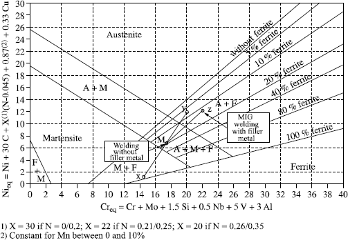
The mechanism is simple and is represented in Figure 12.20.
If two materials X and Y are welded without filler, the respective analyses of the materials make it possible to locate their representative points on the diagram. The representative point of the molten metal is located at the barycenter of the two items X and Y, namely the middle of line XY if the two materials are molten in equal quantities (point M).
If two materials X and Y are welded with a MIG process and filler Z, the analyses make it possible to locate items X, Y and Z on the diagram, the point representative of the mixture XY is as previously (point M), the representative point of mixture XYZ is at the barycenter of the points M and Z, taking account of 25% dilution in this example (point B).
It would be possible to carry out the calculation using the weighted content of each element in the molten metal, but that is generally longer and moreover less visible.
The addition of Bystram diagrams makes it possible, by positioning the representative point of the melted zone, to forecast if a welding without filler is possible, risky or unadvisable; if a filler is necessary; and, in this case, which filler is best adapted to obtaining a risk free melted zone.
12.10. Finishing of welds
Finishing concerns the cleaning of beads after the welding operation. Indeed, the corrosion resistance of stainless steel welded joints can be strongly affected by their surface quality. In all cases, this cleaning will be all the easier the better the protection in the course of welding (protection on both sides, use of a sufficiently long training shields, etc.). Cleaning of welded stainless steels joints can be carried out by various processes (as described in the procedure EN 1011-3: 1997 classification index 89-101-3), employed singly or in combination.
For brushing, special brushes made of stainless steel wire or another compatible material are recommended. In general, this technique is not appropriate for eliminating very adherent impurities. It is recommended that special attention is given to the use of rotary brushes because these are likely to deform the surface and to cause microcrevasses which will reduce corrosion resistance. It is sometimes necessary to follow brushing with a chemical cleaning.
Shot-blasting or sand-blasting products must be free from pollution by iron or non-alloyed steel. This technique is used to eliminate the adherent impurities and also to create residual compression stresses on the surface of the parts. Among the products recommended for shot-blasting are glass and stainless steel.
For grinding, it is recommended we use special disks, bands or grinding stones, free from iron. It is advisable to avoid excessive grinding, which damages the surface and thins the base metal. This technique is also used to eliminate the vast majority surface pollutants and to obtain a regular transition between the welding and the base metal. A light chemical clean can be carried out after grinding.
Scouring eliminates surface oxides or surface layers by chemical reaction. An acid medium is used, whose composition depends on the steel type, the temperature and the cleaning duration. It is necessary to carefully eliminate all the scouring products after the operation.
The weld cleaning operations quoted above, mechanical or chemical, not only removes oxides but also the passive layer of the stainless steel. To accelerate the reconstitution of the passive layer, it is recommended we carry out a passivation operation after chemical or mechanical cleaning.
In general, electrolytic polishing is applied to unstabilized steels in order to obtain a smooth surface, and thereby optimal corrosion resistance.
For optimal corrosion resistance, the most effective processes are chemical scouring and electrolytic polishing.
Lastly, and although it is not a question of a finishing operation per se, a decontamination operation is advisable, especially in workshops not solely dedicated to handling stainless steels. The purpose of this decontamination, similar to passivation in its process, is to avoid any traces of foreign matter, especially ferrous particles, from reaching the surface of the part.
12.11. Glossary
Austenitic stainless steel: stainless steel whose structure is austenitic in all temperature ranges. Austenitic stainless steels are of the iron-chromium-nickel type (molybdenum).
Austeno-ferritic stainless steel: stainless steel whose structure at room temperature is made up of approximately 50% austenite and 50% ferrite. Austenoferritic stainless steels are also called “duplex”.
Ferritic stainless steel: stainless steel whose structure is mainly or only ferritic in all temperature ranges. Ferritic stainless steels are of the iron-chromium type (molybdenum).
Martensitic stainless steel: stainless steel with an austenitic structure at high temperature, liable to undergo phase transformations on cooling:
– austenite: martensite by hardening,
– austenite: ferrite + carbides by slow cooling.
Chromium equivalent Crq: calculated value in which all the alpha gene elements are translated in the form of chromium by the means of coefficients.
Scouring: scouring is a chemical surface treatment of steels which makes it possible to remove oxides which are formed on the metal surface.
Decontamination: chemical operation which dissolves non stainless metal particles, primarily ferrous, deposited on the metal’s surface at the time of cold transformation or completion — finishing of the metal.
Dilution: quantity of base metal remelted at the time of a welding operation, brought back into the total volume of the molten pool.
Alpha gene element: element supporting the formation and stabilizing of the ferric structure. The principal alpha gene elements are Cr, Mo, Si, Al, Ti, Nb, V.
Gamma gene element: element supporting the formation and stabilizing of the austenitic structure. The principal gamma gene elements are Ni, C, N, Cu.
Nickel equivalent Nieq: calculated value in which all the gamma gene elements are translated in the form of nickel by the means of coefficients.
Passivation: chemical surface treatment of the metal which makes it possible to remove from it the polluting elements which could be deposited there and to accelerate the formation of the passive layer.
PREN: pitting resistance equivalent number, corrosion resistance index by puncture.
γ austenitic structure: austenite is a face-centered cubic structure which presents in the softened state the following properties:
– soft but supremely work-hardenable,
– very malleable and workable,
– non-magnetic.
α ferritic structure: ferrite is a body-centered cubic structure which presents in the softened state the following properties:
– soft but not very work-hardenable,
– malleable and fairly workable,
– magnetic.
α′ martensitic structure: martensite is a body-centered cubic structure deformed and hardened by the presence of elements in supersaturation. It presents the following properties:
– hard and fragile,
– not very malleable and unworkable,
– magnetic.
HAZ: heat affected zone.
MZ: molten zone.
12.12. Bibliography
[CAS 68] CASTRO R., DE CADENET J.J., Métallurgie du soudage des aciers inoxydables et résistant à chaud, Dunod, Paris, 1968.
[COZ 98] COZAR R., MOIRON J.L., Ecole Inox Ugine S.A., presentation 1998.
[MOI 96] MOIRON J.L., BONNEFOIS B., Soudabilité des aciers inoxydables, Institut de Soudure 1996.
[MOI 00] MOIRON J.L., BONNEFOIS D., CUNAT P.J., Souder les aciers inoxydables, OTUA 2000.
1 Chapter written by Jean-Louis MOIRON.
