Chapter 13
Welding Aluminum Alloys 1
13.1. Metallurgy of welding
13.1.1. Weldability of aluminum alloys (steels/aluminum comparison)
The weldability of aluminum alloys is, unlike carbon steels, not linked, as with carbon steels, to the problem of transformation phases which, coupled with dissolved hydrogen and the mechanical constraints, can lead to weld brittleness. Their weldability criteria 1 depend, like austenitic stainless steels, on the susceptibility to hot cracking (solidification cracking). The compatibility of metals to be welded and the choice of the filler metal are also important points, because they can cause a lack of bead ductility.
Equally, hydrogen does not have the same effect on aluminum alloys as it does on carbon steels (cold cracking). With aluminum alloys, it causes gaseous porosities because of the great difference in solubility between the liquid and the solid (0.036 against 0.69 cm3/100 g at a melting point of 660°C). This gas is eliminated in practice during the production of semi-finished products but it is sometimes present in castings. It can be produced during welding (see section 13.3.1).
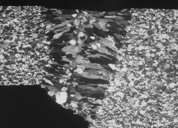
Figure 13.1. a) Hot cracking: 2024 filler 5356 (TIG); b) brittleness of the molten zone: 5083 filler 4043A (TIG)

Pressure die cast components are not weldable because the gas dissolved during their manufacture is expelled during welding.
In practice, the calculation codes and the standards recommend the properties of use and, in particular, draw up the list of alloys that are weldable or non-weldable by arc processes, which does not necessarily mean they perform in the same way with different techniques (resistance, electron beam welding, etc.).
Generally the metallurgical state does not affect the weldability of aluminum alloys. Thus, it is possible to weld an alloy whatever the work hardened state (H1x and H2x) or the thermal state. On the other hand, the assembly properties depend on the welded metal and this state. Indeed, with aluminum alloys, the heating of the material by the arc or the molten metal leads most of the time to a softening of the base metal (see section 13.6), unlike carbon steels which it tends to harden. This heat affected zone (HAZ) is not visible by macroscopic or microscopic observation; its extent depends on the welding process.
Work hardened alloys (the 1000, 3000, 5000 series) in the H states (wrought and restored) lose their properties by excessive heating of the metal, which entails a partial recrystallization of the HAZ, except for the O states (annealed) and H111 which corresponds to an annealed state subjected to subsequent planishing. The strength of the joint is equal to that of the base metal, in an annealed state, whatever the original state: annealed or work-hardened (see section 13.5.1).

Structural hardened alloys (the 6000, 40000 series) generally used either in a quenched and artificially aged state (T5, T6) or more rarely in a quenched and naturally aged state (T1, T4), undergo a complex treatment. The joint strength is equal to an intermediate value between that of the thermally treated base metal and that of quenched, naturally aged, metal. Cast and thermally treatable Al-Si-Mg alloys such as 42100 (Al-Si7Mg03) in the T6 state follow the same rules. Weldable 7000 alloys delivered in the T4 state have the effect of regaining their original properties after a maturation period lasting several weeks after welding.
The loss of mechanical properties following welding is irremediable with work-hardened alloys but the softened zone can be partly regenerated with heat treatable alloys 2. If the complete heat treatment (setting in solution, quenching and tempering) is not possible on large deformable structures, a post-welding tempering treatment is sometimes feasible. It is very interesting when welding is practiced between the quench and temper with 6000, 7000 alloys and on 40000 castings. In the case of a post-weld process, care must be taken to use a filler susceptible to hardening (see section 13.2.2).
Unlike carbon steels (but like certain stainless steels), all aluminum alloys, but more particularly alloys of the 6000 and 7000 families, are sensitive to welding energy. This must be reduced as far as possible in order to minimize the remelting of the intergranular phases (over burn phenomenon). This phenomenon, called liquation and associated with shrinkage stresses, can generate microscopic cracks in the HAZ. To a lesser extent, welding with a controlled energy reduces recrystallization of 1000, 3000 and 5000 alloys. An excessive arc height encourages these defects and impairs the mechanical properties of the weld.
In terms of welding temperature (temperature between passes, pre-heating), we will endeavor not to exceed 80°C for heat treatable alloys and 120°C for wrought alloys. Stress relief processes using heating are seldom used with aluminum alloys because it is necessary to reach temperatures and times corresponding to the softening of the majority of the alloys (250°C for 12 hours). In certain cases, temperatures ranging between 100 and 200°C affect their properties during use (mechanical characteristics of the 6000 and 7000 types, and corrosion performance of the 5000 types, etc.).
13.1.2. Filler metals
Although the majority of alloys are weldable without a filler metal, it is practically always required to have a sufficient welded section, to be able to fill the shrinkages, sags and gaps and to prevent hot cracking.
Additionally, the filler wire forms an integral part of the process of MIG welding.
Generally, the welding of all aluminum alloys is possible with an Al-Si filler and particularly 4043A. Indeed, as the maximum sensitivity to hot cracking ranges between 0.5 and 1% of silicon, the risks are avoided by dilution ratios 3, usually obtained in welding.
This advantage is coupled with low solidification shrinkage, which limits the stresses in the bead and reduces deformations. However, if it serves as an “all purpose” alloy, it does not constitute the best choice in the following cases:
– with 1000 series alloys for which good corrosion resistance or an optimal electric conductibility is required and thus demands a filler of comparable nature (in decreasing order of purity: 1080A, 1050A, 1100);
– for the welding of 5000 alloys with more than 2% magnesium, where magnesium alloys are exclusively used 4 (in ascending % order Mg 5154, 5554, 5754, 5654, 5087, 5183, 5356, 5056, 5556A);
– with 6000 and 7000 alloys when a good static strength is required, especially when the molten zone and not the HAZ (see section 13.5.1) is the weak link, the use of 5356 or 5183 is preferred;
– when a uniform color is required, after anodization, between bead and base metal, a composite filler is employed when possible (1000, 3000, 5000).
Lastly, some wires are imposed by certified organizations for specific applications (5183 for the welding of marine plate alloy 5083 for example).
4043A, even those higher silicon loaded alloys (4045, 4047A), are the basic fillers for the welding and the repair of castings.
Other filler grades are used in very specific operations:
– 3103 to obtain a uniform color during the anodization of 3000 alloys;
– silicon alloys for recharging of castings of particular grades (4009, 4043A, 4045, 4047A, 4145);
– 2319 for the welding of 2000 weldable alloys in particular 2219;
– 4009 and 4145 for the welding of 2000 weldable ones and the recharging of the castings of the series 45xxx and 46xxx;
– 5180 with weldable 7000 alloys, in particular with 7020 in significant thicknesses, and/or if a post-treatment is carried out;
– 4010 and 4643 with the 6000 series and for castings of the 42xxx and 43xxx family in the case of a thermal post-treatment to increase mechanical properties.
The filler metal recommended to weld in TIG and MIG for the various alloy combinations is given in Table 13.1 [EN 99]. In each box, at the intersection of the lines and the columns corresponding to basic materials, the best filler metal is indicated. This is selected according to three criteria:


– maximum mechanical properties of the molten zone (top line);
– corrosion strength (middle line). As for corrosion, the best color uniformity after anodization is obtained using the filler wire grade closest to the metal to be welded. When welding alloys of the 6000 series, 4xxx fillers, which give a dull gray color, should not be used;
– operational weldability (bottom line) including hot cracking and wetting. This property induces a bead shape favorable to fatigue strength.
The choice of metal is often a compromise between these considerations.
Welding generally does not pose corrosivity problems with a suitable filler 5. However, the case of wrought weldable 7000 alloys must be noted, as they have a poor corrosion behavior in a quenched naturally hardened T4 state (exfoliant corrosion). The HAZ of these alloys (in the T6 and T4 state) must for that reason be protected. Post-tempering improves the problem appreciably.
13.2. Welding techniques
13.2.1. Introduction
Welding techniques for aluminum alloys are numerous, the majority derive more or less from those used with other metals, steels in particular (resistance welding, arc welding, etc.). However their physical, physico-chemical and mechanical properties have necessitated the adaptation of existing processes but also allowed the development of new welding techniques. Thus, the presence of a very stable oxide, high electric and thermal conductivity precluded welding using coated rods; the weak hot properties led to the development of friction stir welding (see section 13.2.5).
We will cite the most current techniques here, without going into detail about the principles but specifying the adaptations and the characteristics that aluminum alloys impose. The choice of technique depends on many criteria, such as the shape of the parts, the thickness of the products to be welded, the productivity aimed for, the level of weld quality, capital investment, the degree of automation, etc. It will be sufficient to give background information knowing that comparison is not always possible.
13.2.2. Arc welding processes (TIG-MIG)
Two processes of arc welding, TIG (tungsten inert gas) and MIG (metal inert gas), are employed with weldable aluminum alloys. They use a plasma to transfer the heat obtained by ionization of an inert gas (argon, helium or their mixtures) in the passage of an electric current between the part to be welded and an electrode, which can be refractory (TIG) or formed by the filler (MIG). The gas is also used to protect the fused metal against oxidation.
In theory, argon is used because it offers a better protection (higher density than air), although a plasma arc that is easier to generate (weaker ionization energy) and lower cost. Helium is generally used to obtain a greater penetration (better heat transfer) in MIG and continuous or pulsed TIG. The use of a mixture can also be useful but with a proportion of He at least equal to 50%. The addition of other gases (NR2, O2) has never revealed substantial advantages.
The selection criteria of the process is based mainly on the productivity (automation, welding speed), on the thickness of the products to be assembled and on the weld quality required.
The MIG process incorporating filler metal delivery, comprises only one torch and as a result of this is easily automated, and a fortiori capable of robotization. The TIG process, on the other hand, often remains a manual process, because automatically it is necessary to separately manage the supply of the wire in the weld pool, a delicate operation, especially at its outset. Consequently, such a process is not easily robotizable with filler. In manual TIG, the degree of intervention in the course of welding is total whereas in MIG all the adjustments must be made on test pieces.
The MIG process allows faster welding speeds than TIG (generally between 0.4 and 1.5 m/mn against 0.2 to 0.4 m/mn according to the thicknesses to be welded). From the perspective of its use, the TIG process requires, compared to MIG, more careful surface preparation (see section 13.2). On the other hand, it gives better bead quality. In MIG, this quality (penetration, bead form, etc.) is often dependent on edge preparation of the products to be welded.
It should be noted that MIG welding, a higher energy process than TIG, involves more localized heating, thus the deformations generated by welding are less. These two techniques make it possible to obtain welds of virtually identical mechanical characteristics. However, on structural hardening alloys, MIG produces welds that are tougher overall (see section 13.5).
Welding is always carried out by “pushing” the torch towards the unwelded zone; it is tilted at approximately 80° to the surface of the part, in the direction of displacement so as to achieve a better gas protection.
The welding is preferentially flat and in a half-risen position, although cornice and overhead welding do not present a particular problem. On the other hand, a descending welding position is to be avoided so as not to weld onto the molten metal bath (a common cause of lack of penetration).
With MIG, butt welding on a support slat is highly recommended to remove the risks of burning-through and to guarantee total penetration. The slats can be integrated to good effect right from the design stage of castings and profiles (see Figure 13.21). No protection on the reverse is necessary, unlike with stainless steels.
Care should be taken to ensure a good electrical contact of the earth clamp; the failure to do so being a common cause of bad starts to the welding or an impairment to arc stability due to the presence of alumina on the surface of the parts (see section 13.3.1).
13.2.2.1. TIG alternating current
The electric arc is formed between a tungsten refractory electrode and the part to be welded. Unlike with stainless steels, an alternating current is used. During the negative phase on the piece, there is a scouring of the alumina layer present on the aluminum surface and penetration during the positive phase at the electrode. For this reason the end of the electrode is rounded. The diameter of the electrode is in direct relationship to the welding current: 35 to 50 A/mm of thickness to be welded. Generally, a diameter equal to this thickness is recommended.
The sources are now of chopped type and make it possible to reduce the scouring effect by shifting the polarity towards the positive at the electrode. The filler is introduced into the molten metal weld pool in the form of a rod (manual welding) or wire (automatic welding). As the welding energy is independent of the filler, the process is very flexible; it makes it possible to weld manually with significant gaps (several times the thickness for products under 3 mm) and is well adapted to repair.
Generally, it is a manual process used frequently for the production of individual parts, and demanding great dexterity. It is used in all cases where high quality is required, in particular to carry out water-tight weld beads. The welding speed is controlled by the operator, who can control the energy and the filler quantity as he observes the molten weld pool.
The thickness of products to be welded ranges from some tenths of a mm and is in practice limited to 5 or 6 mm. Above this, there is difficulty in melting the metal, while the distortions due to overheating become significant. For thick materials, a process with a DC (or pulsed) current is used but more usually the choice favors the MIG process.
13.2.2.2. DC and pulsed current TIG
The TIG process is also used with a smooth or pulsed DC current. The process uses helium exclusively as a protective gas, but activation of the arc is carried out using argon, which is more easily ionized. The current is direct, i.e. the electronic transfer, is made from the cathode (electrode) towards the part. In this case, there is no scouring phase applied to the oxide coating (nor of erosion of the electrode). On the other hand, the current is easily controllable, making it possible to weld products ranging from 0.01 mm to 10 mm in thickness. The refractory electrode is made of tungsten containing oxide particles (generally 2% ThO2, but also 2% CeO2 or 5% (ZrO2) to maintain the grinding angle 6. It is sharpened at an angle between 15° and 120° according to the thickness of the part to channel the electron emission. As the arc height is low (some tenths of a millimeter), this process is almost exclusively used for automatic welding. However, its use in the repair of thick parts (castings, molds for the plastics industry, etc.) should be noted.
An alternative process uses a pulsed current (frequency of a few Hz) which offers the advantage of better control of the heat transfer thus better control of penetration depths and bead width. This pulsed mode results in hot phases and cold phases, which generates a layered solidification that refines the structure and reduces the segregations.
13.2.2.3. Metal inert gas
MIG is a process derived from MAG (metal active gas) and applied to steels which use a filler wire (generally 1.2 but also 1.6 even 2.5 mm for thick products) as a consumable electrode and a neutral gas (generally argon) to form the plasma. The latter is maintained by controlling the arc height, which depends on the wire feed speed and the welding voltage. The electrical contact of the wire in the torch is ensured via a copper contact tube. The low rigidity of the filler wire necessitates the use of spools, with appropriate drive rollers which push the wire to the torch through a PTFE sheath and thus facilitate unwinding (there is a risk of seizing with a steel sheath). The torch can benefit from being equipped with a traction system (push-pull system) which allows better regulation of wire speed and arc height by also avoiding the phenomenon of wire buckling on initiation. Its use is essential in robotized welding.
The process is less flexible than TIG because the welding energy is proportional to the quantity of wire applied. To optimize the bead, the welder can generally regulate three parameters:
– the wire speed, proportional to the welding current (and, indirectly, to the thickness of the products to be welded),
– the welding speed,
– the arc height, proportional to the welding voltage.
With aluminum alloys, the pulverization (spray arc) mode of metal deposit is maintained by a high arc voltage (the short-circuit or globular modes used with steel are not suitable). This problem has for a long time limited the minimum thicknesses for welding to 3-4 mm. A reduction in energy can be obtained by changing the arc mode (pulsed current) thus causing a regular detachment of the metal drops. The voltage and average current reduction makes it possible to weld thicknesses from 1.2 to 1.5 mm.
Certain so-called synergic welding equipment integrate, for each wire/gas combination (diameter, nature), presettings of the numerous parameters (high low currents and voltages, frequency, etc.). These synergic curves, a function of wire speed, are time-saving when setting up. Welding programs already used are stored in memory and this facilitates the manufacturing process (there is the possibility of working in program recall mode for robotized production).
From a practical perspective, it remains necessary to adjust the arc voltage 7, because depending on the products to be welded and of the position of welding, inter alia, penetration problems, porosities or lack of sidewall fusion can appear.
Such electronically regulated equipment also uses the programming of a welding cycle 8 (see Figure 13.3), which allows a pre-heating and thus avoids lack of penetration (lack of fusion) at the beginning of the bead as well as the appearance of a final crater (shrinkage pipe with risk of hot cracking) when the arc is extinguished. It should be noted that the displacement of the torch is carried out at the end of the pre-heating slope. Certain welding equipment also has a high current pulse (700 A) which optimizes initiation and thus avoids wire entanglement when beginning without an arc. The process is thus well suited to the production of small beads (<50 mm) and to robotized manufacture.

The development of a twin wire technique should be noted, which allows an increase in the metal deposited but especially a considerable gain in welding speed (up to several m/mn).
Some manufacturers also offer equipment for robotized welding which optimizes the relation between power and metal deposited. The welding of thin materials (below 1.5 mm) becomes less sensitive to whether parts are in contact or there is a gap, if they are of dissimilar thicknesses, etc.
Table 13.2. Summary of bead quality problems in MIG
| Problem | Cause | Remedies |
| Insufficient penetration | Insufficient welding energy | Increase the wire feed speed Carry out edge preparation on products >6 mm Use a gas other than argon 9 |
| Inadequate preparation | Open the chamfer to decrease the heel on thick products | |
| Torch displacement too rapid | Decrease the welding speed 10 | |
| Excessive arc height | Decrease the welding voltage | |
| Excessive penetration | Excessive energy | Decrease the wire feed speed |
| Inadequate preparation | Optimize edge preparation on thick products | |
| Excessive bead convexity | Excessive wire volume | If the penetration is correct, optimize the edge preparation of the products and consequently adapt the wire feed speed |
| Torch displacement too slow | Increase the welding speed | |
| Excessive arc height | Decrease the arc voltage | |
| Bead too wide | Torch displacement too slow | Increase the welding speed |
| Excessive arc height | Decrease the arc voltage | |
| Finely distributed porosity | Excessive arc height | Decrease the arc voltage |
13.2.3. Electric resistance welding
This is a technique derived from that used on steel but, because of the high electric and thermal conductivity of aluminum alloys, lower hardness and the sensitivity to hot cracking, the equipment has been significantly adapted.
The principal differences are the following:
– use of more powerful machines, in particular using tri-phase currents, even intermediate frequency, rectified for thicknesses >3 mm;
– use of large radius electrodes, typically 100 mm, to limit the hertzian pressure under the electrode;
– use of a welding cycle (current/pressure) adapted to remove projections and to reduce internal defects (cracks and porosities).

The thermal properties of aluminum alloys (see Table 13.3, section 13.4.1) necessitate very short welding times. For this, it is necessary to use high current intensities. In the same way, a highly resistant oxide coating must be obliterated by significant deformations. It should be noted that the high contact resistance is favorable to the formation of the molten zone (nugget) at the interface, thus facilitating the welding of thin products on thick products.
Figure 13.5. Weld of 5182-O 1 mm thick on 6016-T4 1.2 mm thick (automotive application) 11

The majority of alloys, those of the 2000 and 7000 families (2024, 7075, etc.), are weldable using this process because the compressive character eliminates any risk of hot cracking.
Continuous seam welding is not suitable for aluminum alloys because it induces too much deformation in the same way, while resistance butt welding is not used because of the very high currents necessary, thus flash welding is preferred.
13.2.4. Flash welding
Flash welding relies on the initiation, between two parts to be welded, of an electric arc which melts the materials superficially. It is followed by a forging operation which expels the molten metal and creates a very limited HAZ.
The process is generally used in discontinuous butt welding (connections in metal joinery, wheel rims, etc.) or uninterrupted in tube manufacture (welded tubes starting from a roll of sheet metal).
All the alloy families are weldable by this process, and in particular 7000 alloys (7075).

13.2.5. Friction welding and friction stir welding
The friction welding technique is limited by the need to put at least one of the parts to be assembled in rotation 12. Its application remains marginal and is limited to cylindrical parts and mainly to aluminum/copper assemblies for electric connectors.
The process of friction stir welding (FSW in the literature) is recent and relies on welding without fusion, obtained by a strong shearing of the matter by means of a pin/rotating tool which mixes the metal of the materials to be assembled without melting them. The reduction of the material flow stress is achieved first of all by a heating of metal by friction with a plate on the surface of the metal before the displacement of the tool, which leads to gradual creation of the weld. The plate also makes it possible to contain metal and to maintain a pressure thus avoiding the ejection of metal away from the welded zone.
The process offers the following advantages:
– all alloys are weldable,
– no porosities, which means reduced surface preparation, — no filler metal or shielding gas,
– no fumes or metal spatter and no UV emission,
– reduced deformations compared to arc welding.
The process is mainly used with 6000 alloys (6060, 6082) because of high welding speeds, but also with the 2000 (2024, 2219, etc.) and 7000 series (7075, 7049, etc.), the majority of which are not weldable by the arc processes.


13.2.6. Electron beam welding
Welding depends on the material fusion under the impact of an electron beam accelerated by a magnetic field and focused on the part in a vacuum chamber 13. The process is very flexible, and enables the welding of parts a few hundredths of a mm to 250 mm (limit of the machines available on the market).
The power required depends on the thickness of the products to be welded; generally, it is considered that 1 kW is necessary to penetrate a thickness of 3 mm.
Practically all alloys are weldable (1050A, 5083, 7075, 2024, 6061, 42100, 48000, etc.). The problems of hot cracking are very much reduced if low welding speeds are used. However, these speeds are much higher than with traditional arc welding techniques, since 5 m/mn can easily be attained. The reduced sensitivity to hot cracking is also due to low heating of the products to be welded; this also results in reduced deformations which are limited to the shrinkage of the molten metal. Welding is carried out without a filler, but alloy foils can sometimes be used to mitigate cracking.
The HAZ is quasi-non-existent and the molten zone generally constitutes the weak point of the weld.
The favored method is butt configuration. Fusion is carried out gradually with a keyhole effect; the welding is generally carried out throughout the parts to avoid the defect of beam extinction (shrinkage pipe). The strong energy density often produces metal vaporization; also, certain elements with weak vapor tension have a lowered concentration in the molten zone. This is particularly true for zinc and magnesium.
The process offers useful advantages with hollow products such as tubular sections and hollow castings because welding can be completely carried out through the walls. The most appropriate configuration is butt welding; no chamfering or preparation needs to be made on the parts to be welded.
On thin products it is also possible to carry out welding by transparency (lap weld).
It is imperative to have clean surfaces, chemically cleaned if possible, to prevent the appearance of porosities. Welding is usually carried out on machined parts in order to remove gaps as far as possible.
13.2.7. Laser welding
The fusion of metal is obtained by monochoromatic coherent radiation focused on the part to be welded so as to obtain a high energy density ranging between 10 and 100 kW/mm2. Two types of laser sources are available:
– CO2 gas laser (wavelength 10.6 µm) which enables the use of high power levels, but which permits beam transport solely by mirrors. The process is thus limited to plane welding (extremely difficult for robotization);
– solid YAG laser (wavelength 1.06 µm), which uses lower power levels (5 kw maximum), but which allows beam transport by fiber-optics and thus relatively easy robotization.
The strong reflection of this beam due to the brightness of the aluminum alloy surfaces prevents the absorption required to melt the parts to be welded. It is thus necessary to initiate metal vaporization to form the bead. The presence of elements with low vapor tension (magnesium in particular) thus makes it possible to weld with reduced energy levels. Power levels higher than 100 kW/mm2 are of no use, as the metallic vapors form a plasma which blocks the laser, especially CO2 sources.

Laser welding, along with EB, is one of the rare techniques which allow continuous welding by transparency while working in keyhole mode. The resolution of this problem (due to the oxide coating which prevents interpenetration) allows the production of continuous welds which can sometimes replace spot fastened assemblies (resistance welding, riveting, clinching, etc.) but especially resistance seam welding, which is used infrequently because of deformations. However, bead section limits the weld’s behavior when the thickness of the products to be welded exceeds 2 or 3 mm. As in arc welding, but to a lesser extent, laser welding may induce hot cracking, a problem which can be eliminated by using a filler metal.
The high energy density allows welding speeds of several m/mn (typically 5 m/mn to join 3 mm thick sheets).
The major disadvantage of the laser remains the capital cost and the thicknesses to be welded which remain low (lower than 5 mm).
13.2.8. Other techniques
Other, more marginal techniques can be used with aluminum alloys. Very often, these techniques have been developed to assemble very dissimilar materials and produce heterogenous assemblies.
Explosive welding makes it possible to plate sheets and thus achieve bimetallic combinations, often steel/aluminum, used in arc welding for mixed steel/aluminum structures (a naval construction application).
A technique derived from this is magnetic induction welding, where energy is delivered from an electromagnetic coil. It is especially used to carry out hafted joints (external or internal).
Ultrasonic welding makes it possible to weld small surfaces using a sonotrode. The principal application is the welding of thermocouples to measure the temperature on the surface of a part.
Further techniques include stud welding by condenser-discharge, etc.
13.3. Preparation and use of semi-finished aluminum welding products
13.3.1. Particularities of aluminum alloy surfaces
Aluminum alloys are naturally covered with a very stable oxide film, alumina, whose melting point exceeds that of aluminum (2,030°C). The thickness of this film depends on the manufacturing process of the semi-finished products; it is greater on foundry blanks and hot rolled sheets.
This oxide is susceptible to hydration during manufacture (hardening of 6000 alloys for example) or storage. The hydrates are of two types:
– those formed at high temperature, during hot rolling in particular; they are very stable and can only be eliminated by mechanical or chemical scouring;
– those formed at low temperature (T <90°C), during storage in particular, which are likely to be broken down by a simple heating.
All these hydrates can be to an extent magnesium enriched in the case of 5000 and 6000 alloys.
Finally, the product surfaces can contain grease, adsorbed or condensed water, which, like hydrates, break down under the electric arc (or simply by the heat of fused metal), to give hydrogen. This gas is harmful and generates porosities as soon as it is present in liquid aluminum, which is the case with fusion welding techniques.
The preparation and employment of semi-finished products require special attention to obtain good quality welds. It goes without saying these points could be specific to a technique, but the quality aimed for will always have to conform to the specification schedule requirements.
13.3.2. Storage
In spite of their good corrosion resistance, semi-finished products and aluminum alloy castings must be stored in a dry, ventilated environment because the protective oxide coating can deteriorate.

To avoid condensation, care should be taken that there is no difference in temperature between the storage area and that of welding. It is advisable that the temperature of the products to be welded and the fillers is equal to or higher than that of the dewpoint.
The fillers must be stored in their original packing. Apart from periods of use, it is sensible to store them in heated dust-free cupboards (40°C).
For MIG stations, it is possible to install heated and/or spools with inert gas.
13.3.3. Surface preparation
These stages aim at helping weldability (TIG wettability, fume emissions) but also ensuring good internal bead health (porosities, oxide films). The basic operation is a degreasing with an unchlorinated solvent of the propylene glycol ester type, aliphatic hydrocarbons, hydrofluoroalcanes, etc.
This degreasing can be followed by scouring to obtain very a good bead quality with maximum compactness. Scouring can be carried out, either mechanically using a rotary brush with stainless steel wire or chemically (using soda, passivation with nitric acid and rinsing with water). In certain cases, degreasing and scouring can be carried out together using alkaline detergents or sulfochromic acid scouring agents.
Whereas degreasing is often essential, brushing can be omitted if the products are stored in dry environments and if a very high compactness is not required (class D of standard NF EN 10042). On the other hand, degreasing must always be carried out before brushing to avoid recontamination.
In the case of castings, a sand or shot-blasting is recommended to eliminate the refractory wash. Degreasing is not advised because the volatility of solvents is not always sufficient for them to be eliminated without heating, resulting in grease residues being trapped in surface porosities. Machining of castings should preferably be carried out dry.
In TIG, a degreased surface, a brushing or a chemical scouring of the oxide coating are obligatory to obtain a stable arc and a sufficient wetting of the molten metal. If a great compactness is required, scraping the products, including the filler rods, may be resorted to.
With MIG, for undemanding applications in terms of bead quality (blow holes), it is not necessary to carry out a brushing or a scouring if the semi-finished products were stored in a moisture free environment; a local degreasing is enough. On the other hand, if a low level of porosity is required, degreasing must be followed by a brushing.
In resistance welding, degreasing and scouring are optional if some porosities in the weld core are admissible.
In electron beam welding, degreasing is obligatory and scouring recommended.
For friction stir welding, degreasing is recommended.
13.3.4. Cleaning of the weld beads
In MIG welding, Al-Mg filler wires (5356, 5754, etc.) leave non-adherent black soot on the surface and bead edge. Welds carried out with Al-Si filler wires (4043A, 4047A, etc.) do not leave traces, except at the beginning of the bead, if they are carried out under good conditions (correct adjustment of the equipment, sufficient gas protection of weld pool). Soot can be eliminated by an alkaline washing under pressure. Scouring by immersion is not recommended for hollow products without an effective rinsing (risk of subsequent corrosion).
13.4. Deformations
13.4.1. Introduction
All fusion welding processes, and in particular arc welding, induce deformations and stresses in the welded parts. Deformation and stresses are closely linked, the elimination of the latter often resulting in distortion.
These phenomena, which relate to all materials, are amplified by the physical properties of aluminum alloys (see Table 13.3), mainly their high thermal conductibility which causes significant heating of the parts. This rise in generalized temperature, coupled with the high dilation coefficient of aluminum alloys, causes expansion which it is necessary to allow it to occur as freely as possible, to prevent the overheated parts being plasticized in compression, with residual deformation after cooling. Contrary to generally accepted beliefs, it is more often the heating, and not the shrinkage during bead solidification, which is the source of the problems encountered during the welding of aluminum alloys.

Maintaining parts in position, along with the sequences and the direction of bead execution, are major factors in the reduction of deformations. Deformation caused during heating by clamping used to reduce distortion can be distinguished from that due to the welding itself.
13.4.2. Steel/aluminum comparison (deformation due to heating)
In the case of welding clamped structures 14, the mechanism which causes the deformations of aluminum alloys is the same as that of steel alloys but the effects are very different. On a steel part, the total temperature reached remains significantly lower than 100°C; with aluminum alloys, it is often higher, hence a more significant dilation. No stress appears (see Figure 13.12) as long as the parts are free to dilate.
On the assumption of welding a part 1 m in length, heating leads to a thermal expansion (1) Δl = E.a. ΔT.l of 1.8 mm for an aluminum alloy such as 5083-O, compared to 0.2 mm for a steel of the S235 type, on the basis of the assumption that after welding the average temperature of the steel part is 40°C and 100°C for the aluminum part.
On the other hand, if the assembly is clamped, the part will be compressed in the assembly with an equal compressive stress (2) σ = ε. E = α.ΔT. E. This stress can reach such levels that the material’s yield strength is exceeded, especially in the HAZ 15, giving rise to a reduction in the length of the part. It should be noted in addition that the yield strength drops under the influence of temperature more quickly with aluminum alloys than with steel (see Table 13.4).
Table 13.4. Evolution of the yield strength of various materials according to temperature (duration <5 mn)


As a first approximation, according to formula (2) in the case of a mild steel with a yield strength of 220 MPa, the temperature limit for the metal not to be entirely plasticized is about 100°C, against 90°C for 5083-O. More significant stresses and deformations are inevitable with aluminum alloys compared to steels.
The total shrinkage after welding is translated in a simplified way either by considerable residual stresses in rigid structures or thick products, or by deformations in flexible structures (see Figure 13.14).

To eliminate these deformations or these internal stresses that affect all the parts, the adapted welding process imposes a specific positioning and an order of bead execution (see Figure 13.15). The overall level of the residual stress in the parts thus depends primarily on the edge positioning and clamping.

Holding parts in position will always be achieved by clamping in a direction minimizing the dilation effect during the welding cycle; according to product thickness in the case of sheets, and in a direction parallel to the weld beads for profiles.
13.4.3. Shrinkage
The shrinkage phenomena, which accompanies the formation of a melted zone, are complex because they depend on the chemical composition of the weld pool, and the quantity of molten metal. It is reduced by employing fillers of the 4000 series (4043A and especially 4047A). This shrinkage is in fact the combination of two phenomena:
– a very localized heating of a compressed zone (as described in section 13.5.1), the liquid zone being free from any stress;
– the solidification of the molten zone, which is then subject to tension (with risk of hot cracking if the alloy is susceptible), and thus ends in generalized tensile forces being exerted on the bead zone.
We must keep in mind that a bead is always shorter than the parts at the outset. The deformations can sometimes be reduced by pre-deformations or a positioning that anticipates them. At this stage it is necessary to distinguish transverse bead shrinkage from longitudinal bead shrinkage.
In basic terms, transverse bead shrinkage can be estimated as varying between 0.3 and 1 mm according to the bead shape (fillet or butt weld) and according to its volume (a function of product thickness). In the case of deformable products, it is not uncommon that it results in angular deformations of the welded parts.
Longitudinal shrinkage, always self-restrained, is often transformed on thick products into internal stresses and it is difficult to eliminate it on thin and/or long products without pre-deformation of the parts to be welded (local lengthening of the zone to be welded).
The welding of discontinuous beads (short runs) is used to decrease the amplitude of the deformation from these shrinkages.
13.4.4. Basic rules
To minimize these deformations, there are two rules to respect:
– to allow dilation to take place readily by designing so-called sliding assemblies. These are very often in the form of lap welds in the dilation direction. This type of assembly ensures the parts are held in position and also avoids welding with a gap between products, but it can have repercussions on mechanical strength, particularly on fatigue strength (lapped weld). We may also have recourse to free assemblies to accompany expansion of the component parts. The most exacerbated deformations are noted when fastening is carried out by compressive equipment, the screw clamp being the best example;
– to optimize the bead execution order to compensate for their shrinkage. Thus, the beads will be initially placed in the middle of the parts while moving towards the free edges to limit their self-restraint. In the case of discontinuous (short run) welds, the beads must begin from the middle of the parts to be welded and alternated in order (see Figure 13.16).

As mentioned, shrinkage during solidification can be more significant with aluminum alloys than with steels. This phenomenon can be all the more serious when the welding is performed with a gap. Although the new MIG equipment accommodates welding thin aluminum alloy products, this initial gap is canceled after the first few millimeters of welding under the cumulated effects of dilation and shrinkage. The butt welding of a bead with a gap will result in parasitic deformations or internal stresses.
In the same way, for a unit welded in a rigid assembly, the cumulative shrinkage effects can result in deformations accentuated by a local reduction in the flow stress in the HAZ during the welding of the last beads (see Figure 13.17). As far as possible, the positioning points will be placed at the maximum distance from the welded zones.

The use of spring-loaded or retractable contacts is a means of avoiding these parasitic deformations. It is necessary to bear in mind that transverse bead shrinkage is invariably more significant at the end of a weld than at the beginning. This principle is applied in the example of Figure 13.18, knowing that the deformation of a bead is seldom compensated by a subsequent weld.
Figure 13.18. Accentuation of the deformations at the end of the weld bead (the angular deformation could be compensated by a bead in the lower angle)

It is important:
– to weld two parallel cords in the same direction to mitigate any warping,
– to weld towards the self restrained or low restrained zones, which are often the part edges, that is, the zones with little material and/or less rigid.
13.5. Dimensioning of the welded structures
13.5.1. Static
The presence of welds decreases the mechanical properties of aluminum alloys: it is necessary to take the dimensioning calculations of structures into account. We present below the broad outlines for checking calculations in Eurocode 9 [ENV 99a] for welds carried out by the traditional arc welding processes (TIG and MIG) 16.
Calculations of component strength must take into account the behavior of the zone close to the bead, as well as the HAZ and the molten zone (MZ) itself. Generally the calculation of the HAZ is enough, but checks must be made on both the zones for fillet welds of thick products in particular.
For dimensioning, it is accepted that material strength is reduced in the vicinity of the welds in a uniform way. This softening is expressed using a coefficient ρHAZ 17 which, multiplied by the allowable stress in tension (fo for tension, fu = fo/√3 for shearing), gives an operational limit value fZAT (MPa) that should not be exceeded in the HAZ.
The width of the HAZ depends on the thickness of the products, the geometric configuration, the temperature between passes as well as the welding process. With TIG or MIG processes, the half-width can thus vary between 20 and 40 mm.
Generally, it is considered that the HAZ extends to all thicknesses of the part to be welded.
Table 13.5. Width of the HAZ taken into account in calculations
| Thickness of the products | Width of HAZ (mm) |
| 0 <thick. ≤ 6 mm | 20 |
| 6 ~ thick. ≤ 12 mm | 30 |
| 12 ~ thick. ≤ 25 mm | 35 |
| thick. > 25 | 40 |
These values are generally lower than those of unassembled materials because of the presence of a softened HAZ or a molten zone which does not have the same metallurgical structure.
The softening factor ρHAZ depends on the initial state of the products and the process used. It is tabulated according to the alloy, its thermal state (H or T) and the welding process for 6000 alloys (TIG or MIG).


The bead stress limit fW depends on the metals to be assembled and the filler used (5356 and 4043A).
In the case of a heterogenous weld, the lowest stress limit is used.
The checking of the weld is carried out, by applying the traditional Von Mises criterion to the HAZ, thereby taking account of the reduction of allowable stress fHAZ in the HAZ and fMZ in the MZ.
In the case of fillet welds, the Beta formula, which is also applicable to steel, is used to take into account parallel and perpendicular shearing of the cord. With aluminum alloys, β is taken as equal to 1.

The normal stresses, parallel to the fillet weld beads, are not taken into account in the calculation of the beads.
Moreover, the stability conditions of the parts to buckling take into account the influence of the HAZ by means of an asymmetry coefficient s which is increased in the presence of welds.
The factors of welding dispersion and execution quality are taken into account by using a safety coefficient γMS which reduces the stress limit. For beads carried out with a normal welding quality, this coefficient has the value γMS = 1.25. For beads welded at a lower quality level, the value is γMS = 1.60.
In the case of a fillet weld or lapped joint, the dimensioning calculations of two particular cases that are frequently dealt with are presented below (see Figures 13.19 and 13.20).


13.5.2. Fatigue dimensioning
The fatigue strength of welded structures is governed, as with steel, by the design (configuration of assembly); see Chapter 6.
The broad welding compatibility of alloys allows optimal use of profiles (mainly 6000) and castings (40000) jointly with flat products (5000). Spun and cast semifinished aluminum products offer the advantage of being able to integrate, by their design, end to end configurations capable of improving performance. All these products have the same intrinsic fatigue characteristics once welded, the behavior being dependent on the local geometric stress level (hot spot) and secondly on bead quality [ENV 99b]. Often, the best performance is obtained by strong configurations which will, on the other hand, allow an average quality bead, but a good quality bead execution does not compensate for bad design. It should be noted that given that unacceptable defects are situated more at the beginning of the bead (risk of sticking, insufficient penetration), placing bead ends on free edges is often less harmful for fatigue behavior.
13.5.3. Rules governing the optimal use of welded structures
The first rule consists of placing the welds in zones subjected to little or no loads, the second of using butt welds in preference to fillet welds, because they offer better static and fatigue behavior. Moreover, in the case of butt welding of profiles or castings, it is judicious to place a weld pool support slat on castings or spun half-finished products, possibly including an edge preparation to guarantee consistent penetration (see Figure 6.21).
Certain measures concerning deformations during welding must be taken into account from the design stage. It is necessary to respect the compatible thicknesses between the parts to be assembled.
It should be noted that if a ratio of two is a sufficient safety factor in arc welding, significant variations can be tolerated in transparency welding (laser, electron beam) or in resistance welding (weldability governed by the lowest value thickness). Provision should be made to minimize deformations during welding, by designing sliding joints for example.

13.6. Welding defects
We will mention here the defects most usually encountered during the welding of aluminum alloys, especially with arc welding techniques.
Static behavior is related to the effective bead cross-section whereas fatigue strength is highly dependent on the level of local stresses. As far as static performance is concerned, it is the defects affecting the effective cross-section of the bead which are more harmful. Thus, non-emergent porosities produced during arc welding have little influence on fatigue strength, but can quite seriously affect the static properties of the weld beads.
On thin products less than 2 mm, the risk of pipe shrinkage on the back of the bead can reduce this section, especially in fillet welds.
Misalignment defects and all leverage effects (weldings on only one side on hollow products) are very damaging compared to the intrinsic bead defects, in particular with regard to fatigue.
The most harmful bead defects are lack of penetration, because of the weakening of the section which this involves, and lack of fusion or sticking at the bead edges, which is often caused by too high an arc voltage, particularly with fillers of the 5000 family.
Joint angles and bead convexity must also be mentioned. They can be reduced by using edge preparations in the case of butt weldings 18. Non-emergent gas porosities have little effect on the lifespan (see Figure 13.22).

In Table 13.8, the origin of the most current defects is shown with their IIW identification number, and in accordance with standard NF EN 26520.
| IIW N° | Defects | Probable origins |
| 104 | Fissure crater | Bead end with abrupt arc extinction |
| 200 | Blow holes | Presence of chemical compounds which are likely to break up on the surface (without forgetting the filler which can be dirty or badly levelled) Poor stabilization of the liquid bath Metal “gassed” (castings particularly) Excessive arc height (arc processes) |
| 402 | Lack of penetration | Insufficient wire speed, in particular at the beginning of the bead (lack of current on MIG start-up) Excessive welding speed (or welding on the weld pool) Incorrect chamfer preparation (too narrow, excessive heel) on thick products in MIG Excessive arc height |
| 4011 | Lack of fusion (sticking) | Excessive arc height Insufficient wire feed speed, in particular at the beginning of the bead (MIG) Component too cold (difference in thickness between materials to be welded) |
| 506 | Overflow | Solidification interval different between filler wire and base material (often encountered in TIG with 4000 filler metal) Excessive arc height |
| 5013 | Root undercuts or back shrinkage cavity (only on thin products thick. <2 mm) | Excessive welding energy Excessive gap between the parts Poor torch angle |
| 509 | Collapse | Excessive welding energy Torch speed too slow Poor torch angle |
13.7. Health and safety
The risks related to the welding of aluminum alloys are those generally encountered with other materials (dazzle in arc techniques, thermal burns, fumes and ozone emissions with arc welding processes, etc.). The physical and chemical properties specific to aluminum alloys must, however, be taken into account.
The great reflectivity of surfaces requires particular vigilance concerning dazzling, face protection (integral mask) and protection of all exposed skin parts is essential (in welding of tanks or enclosed vessels); protective filters of class 10 to 13 according to S 77-104 must be used (which are more opaque than when welding steel).
Aluminum alloys are good conductors of heat, so burn risks are increased (protective clothing essential).
The production of ozone is important in arc welding; it should be noted that the emission level is higher with a Al-Si filler (0.15 ppm on average) than with an Al-Mg filler (0.05 ppm on average). This value increases significantly above a welding voltage of 22 volts.
Certain alloys contain small quantities of beryllium (in particular 5000 alloys). Arc welding processes impose the use of fillers with low levels (lower than 0.0008%). Certain alloys are exceptions to this rule (4011). The user must specify this requirement when ordering half-finished products.
13.8. Bibliography
[EN 99] EN.1011-4, Soudage — Recommandations pour le soudage des métaux — Partie 4: Soudage à l’arc de l’aluminium et des alliages d’aluminium, 1999.
[ENV 99a] ENV1999-1, Eurocode 9 part 1: general rules, 1999.
[ENV 99b] ENV1999-2, Eurocode 9 part 2: fatigue, 1999.
[FD 96] FD.CR.12187, Lignes directrices pour un groupement des matériaux pour le soudage, 1996.
1 Chapter written by Michel COURBIÈRE.
1 The classification of weldable alloys [FD 96] and their metallurgy concern conventional arc welding processes.
2 The problem is economic but especially due to the size of structures which for the most part renders the operation impossible.
3 The dilution ratio is defined as the volume of filler metal deposited over the total volume of the MZ (melting zone).
4 Magnesium filler products are divided into two categories: alloys with more than 3.5% Mg and those with less than 3.5% Mg.
5 Aluminum alloys considered unweldable by the arc process generally do not have good corrosion resistance properties.
6 Thorium is a slightly radioactive element, so it is important to take precautions when sharpening and storing electrodes.
7 Some manufacturers also offer modifications to other parameters.
8 This cycle must be adjustable for each programme as it depends on the weld’s environment.
9 In the case of welding thick sheets (e >8 mm), penetration is improved by using helium or a He/Ar mixture (70/30) in place of pure helium.
10 Check that the wire does not strike the weld pool vertically, in which case it would be necessary to increase welding speed (never weld “on the weld pool”).
11 It should be noted that the MZ is offset towards the metal with the lowest thermal conductivity. This general welding phenomenon is also observed in other techniques (MIG, TIG).
12 The tests of so-called linear friction welding have not demonstrated the feasibility for welding aluminum alloys.
13 On steel, the process functions with a “partial vacuum” which cuts down on pumping time. It is not used on aluminum alloys due to their highly oxidizing characteristics. Some installations allow welding at atmospheric pressure provided the beam can be focused at a few mm from the gun.
14 In welding, the term clamping is taken to mean the prevention of expansion along its longest length.
15 The zone close to the bead (20 mm) reaches more than 300°C whatever the alloy.
16 With other welding processes, preliminary tests and measurements of microhardness can be referred to, in order to estimate the extent and the loss of mechanical characteristics in the HAZ.
17 This so-called metallurgical efficiency factor is referred to as β in the DTU aluminum or in the ECCS rules; this is not to be confused with the β of the formula of the same name.
18 It must be remembered that such preparations can be supplied directly and at no extra cost for spun or cast products.