CHAPTER 6
Fabrication Processes and Techniques
…thus the rigid and inflexible will surely fail,
While the soft and flowing will prevail.
Tao Te Ching
INTRODUCTION
Ductility is the ability of a substance to deform plastically without fracturing or tearing. A defining characteristic of copper is its ductility. There are few metals that possess a similar ability to undergo shaping without tearing. Copper alloys, particularly the softer tempers, lack the anisotropic directionality that many other metals exhibit. For centuries, copper has been hammered and shaped to create useful forms by thinning and stretching the metal.
One measure of ductility is elongation of a material while under a load. Copper and many of its alloys, particularly copper–zinc alloys, can be stretched without breaking as loading is applied. Figure 6.1 shows a typical stress–strain graph of copper. The graph shows a flattened stress–stain curve; as load is applied, the copper article will elongate and undergo plastic deformation. The area under the curve represents the toughness of the copper.
Copper work hardens as it is shaped and molded. In repoussé and chasing metalwork, where the ductile copper is hammered and stretched, the copper will work harden with each blow. The hammering is repeated over and over again until very gradually the desired form is achieved. But there comes a point at which the continued hammering is resisted by the work‐hardened metal and there is potential of tearing. Repoussé work‐hardened copper is heated to a point below melting, then allowed to cool. This heating anneals the metal, and it becomes soft and ductility returns. Further hammering and shaping can now occur. This is repeated as each step takes the artist further in the shaping of the work.

FIGURE 6.1 Stress–strain graph of copper.
As copper work hardens, the grains are stretched. This stretching realigns the crystal matrix as sections slip over one another and the copper elongates. Heating the copper causes the atoms to move about from areas of high stress to areas of lower stress. The crystal lattice relaxes, and further cold working can occur. The process can be repeated to a point.
The interesting part is that copper sheet does not display the antistrophic character that most sheet metal forms have. In wrought forms there are differences in physical characteristics along the length and across the length, but shaping with the grain and against the grain afford little differences in resistance. The hammered vase shown in Figure 6.2 is an example of the amazing ductility of copper. Stretching it and conforming it to shapes by hammering, heating, quenching, and rehammering are part of an art form that extends back centuries.
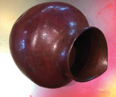
FIGURE 6.2 Hammered copper vase.
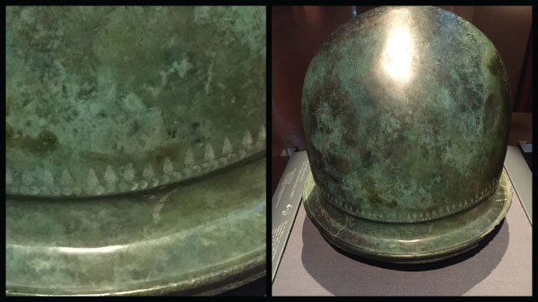
FIGURE 6.3 Ancient Roman helmet hammered out of copper alloy.
Working with copper and copper alloys initially centered around castings to produce cast ornamentation and cast utensils. Helmets and shields were some of the first items using hammered copper (Figure 6.3). These offered some protection from clubs and spears made of wood and rock, but their real advantage was they could be straightened by rehammering, and if damaged, melted down and reshaped.
Some of the earliest swords were made of bronze, an alloy of copper and tin. This alloy was harder than copper alone and would take and hold an edge better. Most early swords were simply wood swords tipped with metal points. Bronze swords and daggers were cast and then forged and sharpened by early metalworkers.
The copper, bronze, and brass forms we use today all have roots going back to these early metalworkers and the designs they created. Here was a hard but pliable material that could be sharpened and strengthened by hammering and, once damaged, melted down and repurposed into a new item.
Copper gave early mankind the ability to work a material like nothing before it. By 2500 BCE many of the forming processes still used for metal today had been developed and were in use. Hammering, shaping, forming, and even welding were mastered by certain discrete regions where civilizations prospered and the metal was available.
FORMING
The ductility of the wrought forms of copper and copper alloys is a significant benefit to be exploited by the designer and fabricator. The condition of work hardening when the metal is cold worked is important to understand and appreciate. All wrought forms have a directionality, or a bias that dictates anisotropic differences in mechanical behavior. This directional bias is induced into the grains of the wrought metal as it is cold worked, stretched into long lengths of sheet, and recoiled. The same is true of bar and rod. Hot rolled plate also has a directional bias, but cold rolling stretches the grains and elongates the internal crystal structure.
In most applications directional bias is not a significant issue; the operator adjusts for the change in responsiveness in the forming operation. There is not significant springback in copper alloy forming, but there can be an increase in forming pressure and potential cracking when cold forming with the grain versus forming against the grain for some of the stiffer alloys, such as C28000. Figure 6.4 shows a variety of items made from copper, including a copper sink, copper shelving, and custom light sconces in which glass was blown into the assembled forms.
Forming parameters depend on alloying constituents, the cold rolled temper, and the direction or orientation of the bend. Additions of zinc, for example, will increase the strength and increase the rate of work hardening of the copper alloy. The higher the temper is, the more springback will be present and the more difficult the metal will be to form. All cold rolled sheets have an anisotropic, or directionality, imparted by the process of cold rolling. Cold roll anisotropy is induced in the long direction of the sheet or ribbon of metal.
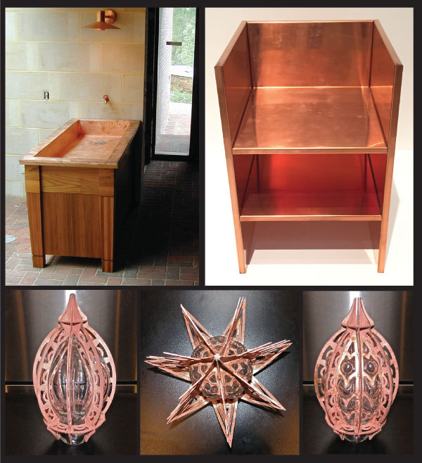
FIGURE 6.4 Various fabricated copper items.
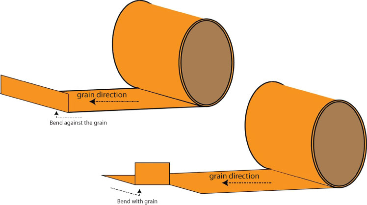
FIGURE 6.5 Bending with and against the grain.
Bending with the grain, as depicted in Figure 6.5, requires less force than bending against the grain. But with copper and copper alloys, the difference can be overcome with modern equipment and skilled operators, so it is not typically an issue. The dual phase alloys—those that have both alpha and beta phases in the crystal structure, which is a metallurgical condition that develops as alloying elements are added to the copper—are more prone to cracking when cold worked. Alloys such as C28000 (Muntz Metal) are dual phase copper–zinc alloys. Zinc is added to copper to around the 40% level. This alloy is difficult to cold work and can crack along tight bends. However, this alloy performs well when the metal is heated and the shape is formed through hot working.
V‐CUTTING
V‐cutting the back of copper alloy sheet or plate removes metal and leaves a small v‐shaped cut partially through the material. This enables a tight fold to occur versus a rounded fold. Figure 6.6 shows the expected result of v‐cutting.
Copper alloys can be v‐cut using a method similar to that used for other metals; however, the back should be reinforced. V‐cutting weakens the corner, and as the bend occurs the metal will undergo plastic deformation. You only have a single opportunity to make the bend. If it is folded, then flattened back out, subsequent refolding will likely crack the alloy at the point of the fold. The technique produces an intriguing appearance in thick sheet or plate forms of the metal, but it has structural limitations. The back can be reinforced with another angle of stainless steel or copper and bonded to the copper alloy by soldering or brazing a support piece or using very high bond (VHB) tape. It is good practice to test the connection and the reinforcement of the corner to ensure that no esthetic issues arise on the visible side. Figure 6.7 shows v‐cut corners on 1.5‐millimeter‐thick C11000 panels at the de Young art museum.
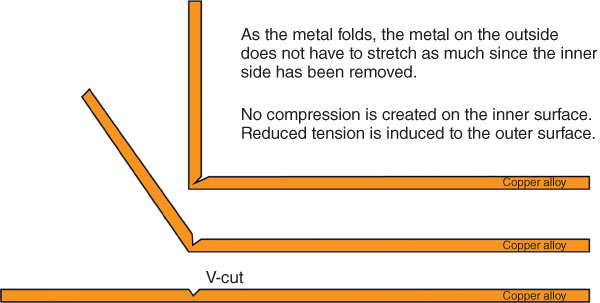
FIGURE 6.6 V‐cutting copper alloys.

FIGURE 6.7 V‐cut corner on panels at the de Young museum of art.
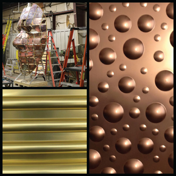
FIGURE 6.8 Shaping copper alloys.
Copper was made for the fabricator. The ability to shape the surface of wrought sheet is unmatched. It's as if you combined clay with steel. Pressing intricate shapes into the surface is what the metal was created for. As depicted in Figure 6.8, copper alloys can be hammered into forms and exploded into curved bubbles or rolled into repeatable waves.
Copper alloys will work harden as cold work is performed on the wrought forms. The work hardening makes subsequent shaping more difficult. The amount of work hardening that can be experienced depends on the alloy. The higher the zinc content, the more rapid the work hardening from cold working the metal. While the C11000 alloy will work harden at a relatively slow rate, the nickel–silver alloy C75400 and the phosphor–bronze alloy C52100 will work harden rapidly and can more than double in tensile strength from fully annealed levels.
Zinc, when alloyed with copper, induces more strength into the copper: as zinc is added, the strength of the alloy is better than that of copper alone. The alloys of copper and zinc that are in solid solution up to around 30% zinc have improved strength but retain ductility. Additionally, these alloys have greater elongation when under load than copper, and work harden at a lower rate than copper. Moreover, when stressed, necking occurs at higher strain rates.
As the zinc increases to 40%, a phase change occurs and both alpha and beta crystal phases develop. Alloys with this level of zinc are excellent hot working alloys and have superior machineability, but they are very poor cold working alloys and can crack under simple forming operations. They can be curved in plate rolling operations but will show significant resistance if the radius is tight. In thick wrought forms, shaping by brake forming will require skill to avoid cracking at 90° bends.
The graph shown in Figure 6.9 indicates the changes in yield strength of a H01 (quarter‐hard) temper wrought sheet, as the zinc is added to alloys C21000 to C28000. At around the 40% zinc that is in alloy C28000, it reaches a maximum. Naval Brass (alloy C46400) has small amounts of lead and tin added to basically the same alloy constituents as C28000, yet the yield strength increases significantly. The temper shown in this graph for alloy C46400 is H02, resulting in higher yield strength than H01.

FIGURE 6.9 Graph of change in yield strength as alloying elements are added.
Yield strength increases significantly as nickel is added. The copper–nickel alloys C70600 and C75200 have a yield strength much higher than commercially pure copper and the nickel–silver alloy C77000 possesses the yield strength of steels. Alloy 35300, known as Architectural Bronze, is an extruded form and therefore the temper is an as‐manufactured temper. Alloy C51000, phosphor bronze, shows a low yield strength when provided in H01 (quarter‐hard) temper. It jumps up considerably as further cold working raises the temper to H02. At this point the yield strength of C51000 is similar to C28000 at an H01 temper.
True bronzes, alloys of copper and tin, are rarely used in art and architecture. The cast alloy C87400, commonly known as silicon bronze, is used in numerous cast sculptures and contains no tin whatsoever. The wrought form of this alloy, C65500, has good strength and ductility. Its yield strength is similar to that of alloy C22000, Commercial Bronze.
There are occasions when the phosphor–bronze alloys C51000 and C54400 are used in wrought forms of plate. These alloys contain small amounts of tin, up to 5%. The alloy can be cold worked but its strength increases rapidly, making subsequent forming more difficult. Annealing the alloy will lower the temper and allow for further forming.
Copper alloys that contain aluminum (C61000, C61300, and C61400) are known as aluminum bronze. These have good strength and hardness. These alloys will form better than the high‐zinc alloys.
Copper–nickel alloys contain an appreciable amount of nickel. Copper and nickel are two metals that are miscible with each other in any quantity. Copper–nickel alloys are ductile and very resistant to corrosion, particularly in seawater. They were once used extensively on the external sides of ships below water to act as protective biocides against barnacles and worms.
The nickel–silver alloys C75200 and C77000 contain zinc as well as nickel. These are available in limited sizes, but they can be cold worked. They are very strong and hard alloys. As they are cold worked, the temper increases, as does the tensile strength.
The ductility of copper and copper alloys allow for tremendous flexibility of shape and form. Used as a thin cladding for surfaces, they will conform to the underlaying shape as if they were painted on the surface. Figure 6.10 shows three examples of thin copper material conforming to unique shapes and surfaces.
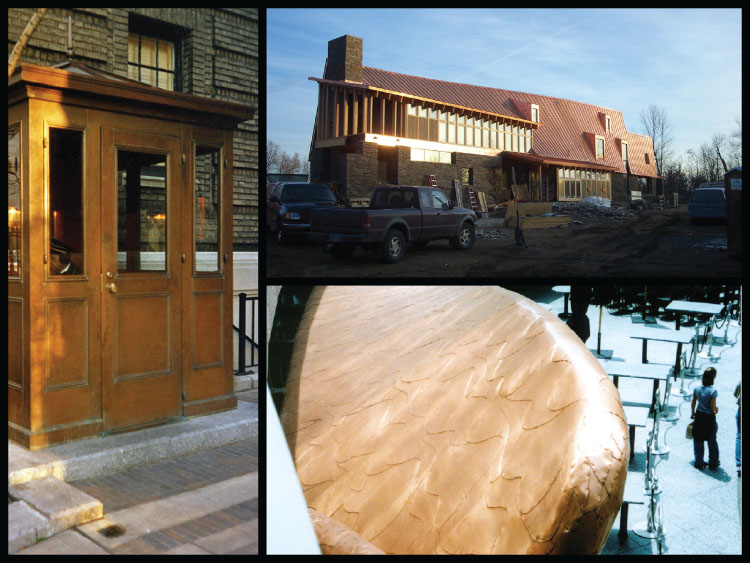
FIGURE 6.10 Copper and copper alloy–clad surfaces.
CUTTING COPPER ALLOYS
Copper and copper alloys can be cut by all conventional cutting equipment. The yield strength of copper and most copper alloys is lower than that of steels. Most of the copper alloys are also softer than many other metals. This makes cutting with steel shear blades and saws more effective. The modern cutting methods of waterjet and laser are common means of cutting copper alloys. Standard plasma will cut copper but will require edge cleanup. The high‐definition plasma cutters will rapidly cut through copper alloy material and produce an edge that requires less cleanup. Knowing how the different cutting methods will respond to copper alloys is important. Not all lasers will effectively cut copper, and some can be damaged by the reflectivity of the molten metal. Plasma can melt copper to make the cut, but the rapid cooling can redeposit the molten metal as a coarse oxide along the edge. Table 6.1 compares the cutting methods used on copper alloys.
Shearing and Blanking
Shearing, slitting, and even hand shears will cut thin copper and copper alloys with little effort. These tools are mainstays in the sheet‐copper fabrication shop. Shearing copper alloys produces a straight‐line cut as the metal is sliced in a way similar to the way scissors cuts through paper.
TABLE 6.1 Cutting methods used on copper alloys.
| Cutting method | Form | Thickness | Speed | Subsequent operations |
| Shearing | Sheet, plate, wire | <5 mm | Fast | Accurate straight‐line cut. Foil sizes are cut with a shear, similarly to paper. |
| Saw cutting | Plate, bar, tube, extrusion | All forms and thicknesses except foil | Slow | This operation is slow and less accurate than other methods. |
| Waterjet | Sheet, plate, bar, extrusion, tube | >0.25 mm | Slow | Thin sizes may shape from pressure. Accuracy is superior. |
| Laser | Sheet, plate | <4 mm | Fast | Very accurate. Can shape from heat. |
| Plasma | Sheet, plate | <3 mm | Medium | Accurate but can shape from heat. Cleanup required to remove the burr produced along edge. |
| Machining | Plate, extrusion, bar, tube | >1.5 mm | Slow | Very accurate. Will need some post‐finish work to remove machining marks. |
Shearing is an operation involving two sharpened and hardened steel blades. One blade is fixed and the other is brought down with such force that a metal strip undergoes severe plastic deformation to the point that it fractures at the surface line where it contacts the shear blades. This fracture propagates through the metal. When there is proper clearance between the cutting blades, the crack that propagates penetrates only a portion of the thickness. One crack will form at the top blade and another crack will form at the bottom blade. These cracks meet near the middle to provide a clean fracture line.
Blanking involves a similar process. A tool with a sharpened edge comes down on a die, and the interaction slices through the copper alloy creating a blank form in the middle of a sheet or strip of metal. The balance is gathered and recycled. The blank is transferred and used in subsequent forming operations. Blanking is used when multiple forms of the same dimension are stamped out, whereas shearing is normally used for one‐off operations or low‐quantity operations.
Saw Cutting
Wrought and cast copper alloys can be cut with cold saw blades. Thick copper alloy material is often saw cut. Heat buildup is minimized because the copper will dissipate the heat generated during the cutting process. A cold saw is a steel circular or band saw. The tip of the blade can be coated in tungsten carbide, synthetic diamond, or titanium nitride. Saw cutting can induce heat into the copper alloy, causing localized distortions along the edge if the saw is not cutting properly or if it is worn out. It is good practice to conceal a saw cut edge in a cover plate or folded under in a lap joint. It is very difficult to achieve an acceptable saw cut edge in thin copper alloy sheet. Extrusions, bar, and tubing are often cut with a saw. The edge usually requires some re‐dressing to remove burrs and soften the cut.
When saw cutting copper alloys, use saws with coarse teeth on thick and hard alloys and fine teeth on thinner forms of copper alloys.
Waterjet Cutting
Waterjet cutting of copper alloys is an excellent method of creating intricate shapes and forms from sheet and plate material. Thin copper alloys can be waterjet cut by leaving tabs to suspend the parts and keep them from bending from the force of the jet of water and abrasive in the water. Cutting with water can achieve fine detail, such as the detail of the leaf art form and grille cover shown in Figure 6.11.
On thick copper alloy plates, waterjet cutting is the preferred means to achieve intricate forms. Waterjet cutting is a means of accurately cutting thick metal plates to produce inserts—such as the brass inserts as shown in Figure 6.12—for inserting in terrazzo flooring or wooden walls to create decorative features.
Waterjet cutting does not induce any heat into the copper parts being cut nor does it interfere with the application of patina or statuary finishing. The gate shown in Figure 6.13 was manufactured from 3‐millimeter‐thick C22000 alloy material and assembled with a 3‐millimeter stainless steel waterjet plate. The C22000 alloy was given a dark statuary finish to contrast with the stainless steel insert plate that adds to the overall strength.
Powerful waterjets can cut all metals accurately, but there are several things to keep in mind when cutting copper and copper alloys. For one thing, careful handling of the finished material to and from the bed is critical. Most waterjets use steel slats to support the material being cut. These slats are often jagged from previous cutting operations. Transferring finished or semifinished plates to or from the bed can scratch and mar the surface of the copper or copper alloy.

FIGURE 6.11 Left: Decorative leaf form by Reilly Hoffman. Right: Decorative grille cover made from the C22000 alloy.

FIGURE 6.12 Waterjet cut thick brass inserts.
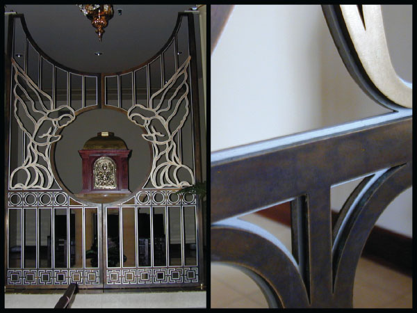
FIGURE 6.13 Gate with waterjet cut angels.
Drilling of these metals should also be conducted carefully. Waterjets initially drill a hole through the metal sheet or plate. This initial force can be significant and shape or bend small parts. Because the metal surface is soft, the initial drill force can etch the surface around the initial point of entry creating a frosted halo.
Laser Cutting
With the advent of the powerful fiber laser, laser cutting has become an invaluable means of cutting copper and copper alloys. Copper has a different light absorption rate from other metals and thus cutting it requires a different wavelength and higher power. Earlier CO2 lasers did not have enough power and molten copper would reflect the light back into the lens, causing significant damage to the laser. A fiber laser doesn't deliver a laser beam in the same way that a CO2 laser does. Instead, power is delivered though a glass fiber. The glass fiber is doped with rare‐earth elements and can support high kilowatt levels.
As compared to the waterjet method, one drawback of using a laser is that it delivers heat energy to the cut; for some intricately cut patterns, this can warp and shape the copper alloy. On a piece with very intricate and extensive cutting, warping can interfere with the cutting head and stop the machine. A warped sheet may require post‐flattening of the cut form or part. Figure 6.14 shows some extremely intricate cuts on 3‐millimeter‐thick alloy C22000. The artist, Jan Hendrix, designed these incredible sculpture forms to be cut from copper alloy for strength and then chrome plated to achieve a mirror‐like appearance.
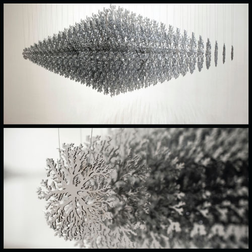
FIGURE 6.14 Laser cutting in Fuga
Source: by artist Jan Hendrix.
The edge produced from laser cutting is clean and precise. There is a slight halo of color that will occur at the cut edge from localized heating during the cutting process. Figure 6.15 shows a laser cut art form designed by artist Jason Pollen. The art was cut from alloy C11000 and finished with Dirty Penny. The copper is 2 mm thick. When the holes or shapes of cuts are small and tight some re‐fusing of the hot copper alloy can occur at the cut, locking the cut out into the cut shape and requiring secondary means of removal.
Fiber lasers will cut copper alloy sheet of 3 mm and less with little difficulty. As with waterjets, the beds are often steel slat, or possibly copper slat. In any event, the molten material created by the laser cutting can redeposit onto the slats, making them jagged and sharp. These will scratch the copper if care is not taken in the removal of the cut parts from these jagged points.

FIGURE 6.15 Laser cut artwork
Source: by artist Jason Pollen.
Plasma Cutting
Copper alloys can be cut with plasma cutting equipment. Plasma cutting is typically performed on two‐dimensional CNC‐controlled tables. The copper alloy plate or sheet is set onto a steel lattice and a high‐energy plasma beam cuts through the metal. Plasma cutting involves creating electrically charged ionized gas and forcing the gas through a small orifice. An electrical current is generated from a remote power source that creates an arc from the copper work piece, which is given a positive charge, and the plasma gas, which is given a negative charge. Plasma cutting can also be performed by hand using portable plasma stations. Figure 6.16 shows hands cut out of 1.5‐millimeter‐thick copper sheet and the final artwork. The edges required cleaning up to remove the coarse dross left along the cut line where the melted copper attached back to the edge.
The gas used for cutting copper is nitrogen or an argon–hydrogen mix. Carbon dioxide and oxygen gases can be used to create the plasma jet, but these will create a darkened cut as the copper alloy edge oxidizes.
Temperatures in the high‐velocity plasma jet can be as high as 22,200 °C, as this highly charged gas melts the metal and blows it away. There is not a lot of heat transferred to the copper, but if there are a number of piercings you can expect warping. Piercing with plasma is similar to piercing with a laser. The energy must “drill” a hole through the metal, and as this concentrated heat sits on the surface for just a moment, the copper will absorb it.
High‐definition plasma cutting systems reduce the heat‐affected zone and produce a fine‐cut line in thin copper. Handheld and less sophisticated systems will have a larger kerf and more oxidation on the edge. The kerf, which is the term used to describe the edge of the cut or the cut itself, will be rougher than that produced with a waterjet or laser. There can be a redeposit of molten metal along the kerf. This redeposit is rough oxide that will need to be removed by filing or sanding.

FIGURE 6.16 The plasma cut copper artwork Hands of Man by the author.
Source: Photo courtesy of the author.
MACHINING
Pure copper does not machine particularly well, as the rapid cutting tools used on machining centers produce long curled tubes that can gum up the tooling. Chatter can form as the more ductile pure copper flexes under cutting loads. Adding small amounts of tellurium, sulfur, or lead will cause the copper trailing to break off into small shards, making the machining of these alloy forms more effective.
Most of the copper alloys considered for use in art and architecture are similar to copper when it comes to machining. The harder, two‐phase alloys that possess both the alpha and beta crystal structures are better adapted to machining processes. Copper–aluminum alloys machine similarly to the way that steels machine. The hardness of these alloys will cause rapid tool wear. The copper–nickel alloys are very difficult to machine because of rapid tooling wear induced by the nickel.
Machining is a broad term, but for the most part it involves the selective removal of small amounts of material by passing a special, rapidly rotating tool over the surface. Table 6.2 discusses the machineability of various alloys that are used in art and architecture. Alloys with good machineability are often referred to as “free‐cutting” alloys. The industry assigns a number to metals reflecting their machineability, with 100 being highly machineable.
Lead added to alloys assists in the lubrication of the cutting action of the tool and causes the trailing to be small and to break away. Leaded nickel–silver alloys will machine better, but the tooling will wear more rapidly than it will for steels because of the nickel content. Many industries machine fixtures, pumps, and special hardware that require machining to tight tolerances. Small parts and fittings are commonly machined from various copper alloys (Figure 6.17).
There are copper alloys designed specifically for the purpose of machining. One, commonly known as “free‐cutting brass,” is a copper alloy consisting of 39% zinc and 3% lead. This alloy, C35300, requires lower cutting forces than aluminum and can be machined more effectively than alloys of steel or aluminum.
As the machining tool addresses the block of C35300 alloy, small shards are quickly and efficiently removed. This reduces post‐finishing and allows for intricate designs to be produced on end or table mills. Machined copper alloys are used in the fabrication of hardware, marine fittings, and valves, and in many other areas where excellent corrosion resistance and durability is desired.
The Museum of the Bible art panels designed by Larry Kirkland and shown in Figure 6.18 were machined from copper alloy C35300. Initially casting was considered as a means of producing the art, but casting would have required numerous unique physical molds, the cost would have been higher, and significantly more time would have been required for fabrication. Machining, on the other hand, is a production process that is accurate and rapid, and was a way to “carve the artwork” out of a metal plate—in a way, a kind of reverse rapid prototyping. Instead of using physical molds, the design was created in three‐dimensional computer code and metal was cut away from a solid 25‐millimeter plate of brass to reveal the lettering. All the material removed was recycled. Figure 6.18 lists the steps used to machine the 25‐millimeter‐thick block of alloy C35300.
A three‐dimensional computer model of each letter was created, and instructions were provided via CNC to an advanced milling machine, where the lettering was cut out of 25‐millimeter‐thick plates. The top image in Figure 6.19 shows the initial mill marks on the surface, while the bottom image is a screenshot of the movement and tool paths of the machining tool.
TABLE 6.2 Machineability of copper alloys.
| Alloy | Machineability | Point of discussion |
| C11000 | 20 | Copper has poor machineability; it gums up tooling. |
| C21000 | 20 | High‐copper alloys possess poor machineability. |
| C22000 | 20 | High‐copper alloys possess poor machineability. |
| C23000 | 30 | The added zinc makes this alloy harder, but still poor machineability. |
| C24000 | 30 | The added zinc makes this alloy harder, but still poor machineability. |
| C26000 | 30 | The added zinc makes this alloy harder, but still poor machineability. |
| C28000 | 40 | This alloy is harder, but still poor machineability. C35300 is similar but machineable. |
| C35300 | 90 | A leaded alloy that is considered free‐machining. Excellent machineability. |
| C37000 | 70 | Good machineability due to small amounts of lead. |
| C46400 | 30 | A hard alloy, but still poor machineability. |
| C51000 | 20 | Poor machineability. |
| C61000 | 30 | Poor machineability. |
| C65500 | 30 | Poor machineability. Nickel content wears out tooling. |
| C70600 | 20 | Poor machineability. Nickel content wears out tooling. |
| C75200 | 20 | Poor machineability. Nickel content wears out tooling. |
| C77000 | 30 | Poor machineability. Nickel content wears out tooling. |
| C79800 | 50 | Improved machineability due to the added lead. |
| C83600 | 90 | A cast alloy with excellent machineability. Considered free‐cutting. |
| C84400 | 90 | A cast alloy with excellent machineability. Considered free‐cutting. |
| C85200 | 80 | A cast alloy with excellent machineability. Considered free‐cutting. |
| C86300 | 60 | A cast alloy with good machineability. |
| C90300 | 50 | A cast alloy with moderate machineability. |
| C97300 | 70 | A cast alloy with excellent machineability. Nickel wears out tooling. |
Bolded numbers are considered free‐cutting alloys.
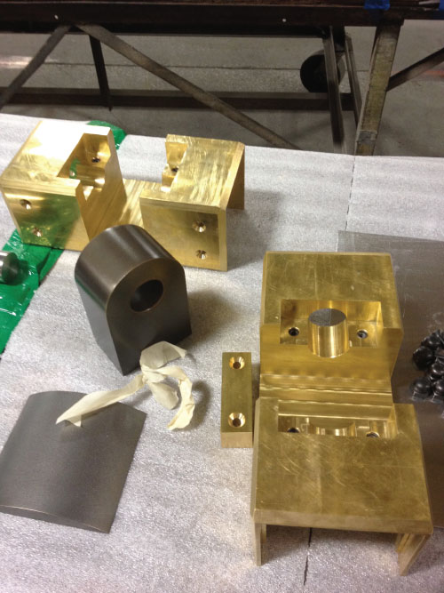
FIGURE 6.17 Machined copper alloy parts.
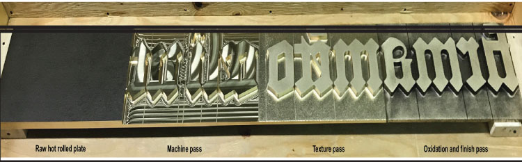
FIGURE 6.18 Machining, texturing, and finishing of panels at the Museum of the Bible.
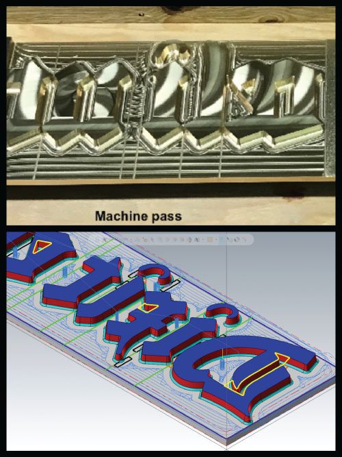
FIGURE 6.19 Top: Initial mill marks on the metal surface. Bottom: Computer image of the machining passes.
For the entryway of the Museum of the Bible, the artist Larry Kirkland chose a copper alloy that would, after texturing and oxidizing, emulate the way the lettering dies used in a Gutenberg press of old would look. The first two pages of Genesis, written in old Latin script, were chosen for the C35300 panels flanking the door. As with a real press, they had to be mirror images. Alloy C35300 was chosen.
The machined plates were needle hammered around the letting to create a special texture, then darkened using a copper–sulfide statuary solution and highlighted to mottle the surface. As Michelangelo once said, “The marble not yet carved can hold the form of every thought the greatest artist has” (Figure 6.20).
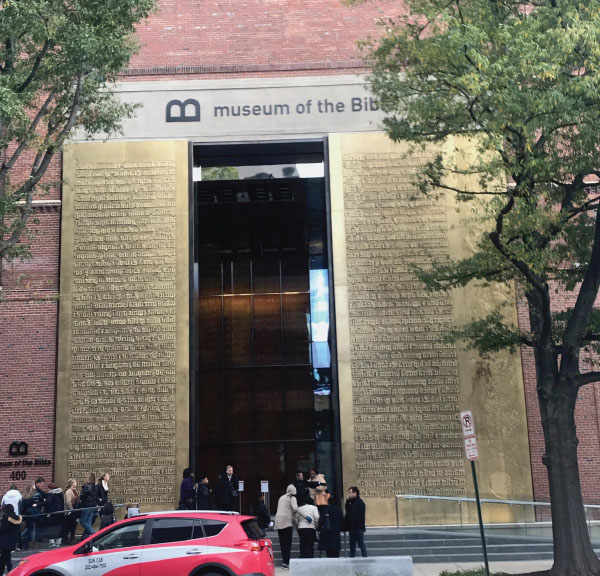
FIGURE 6.20 Machined lettering at the Museum of the Bible, designed by Larry Kirkland.
SOLDERING, BRAZING, AND WELDING
We think of soldering, brazing, and welding processes as inventions of modern age. It cannot be argued that modern welding technology is one of the most advanced and innovative areas of metalworking. But the end result—two discrete metal forms joined together to form one—is a form has been practiced for more than 5000 years. In 3000 BCE the Sumerians, one of the most prolific early Bronze Age cultures, made swords of bronze that had sections joined by hard soldering. The Sumerians even used a flux to braze parts together. It is interesting to think that the processes of joining metal together have been built upon for over 5000 years, as advancements in technology drive the technique to new levels.
Soldering and Brazing
Soldering and brazing are common forms of joining copper and copper alloys. The processes of soldering and brazing are similar. Brazing is sometimes referred to as “hard soldering,” while soldering is occasionally called “soft soldering.” The difference lies in the heat and filler metal used. The general rule is:
| Soldering | Low melting point fillers | Less than 450 °C |
| Brazing | High melting point fillers | Greater than 450 °C |
In each method, only the filler metal and not the base metal is melted. Soldered and brazed joints are strong and can transfer stress across them, but they are not as strong as the parent material.
Soldering and brazing are forms used to join thin copper alloys together or to seal the edges and seams of assembled units with metal filler material. Soldering and brazing form a metallic joint between two metals using thermal processes that melt the filler metal at temperatures below the base metal's liquidus temperature. The metals being joined by the soldering process can be the same or different metals. The filler metal makes a metallurgical bond with the base metals, joining them together. Soldered and brazed joints have the ability to conduct electrical and thermal energy.
Soldering uses filler metals that have low melting points, such as lead, tin, and antimony. Brazing uses filler alloys with higher melting points, such as silver–copper–phosphorus alloys.
Soft solders generally in use today include both leaded and lead‐free varieties. Leaded solders are tin–lead solders with very low melting points. The lead solder combination of 63% tin and 37% lead is considered a eutectic alloy (that is, they both dissolve completely in one another). Because of this, there is a specific temperature at which they transform from solid to liquid. Other lead solders liquify at a range of temperatures (Table 6.3).
Leaded solders are being phased out because of the hazards associated with lead exposure. These solders were in common use for decades and still can be found in common use in the United States. They have been discontinued for the most part in Europe and Japan. The difficulty in replacing them is in the ease of use. Lead has an excellent wetting ability; that is, it breaks the surface tension in the mix and allows the molten metal to flow.
Lead‐free solders have a higher melting point than leaded solders (Table 6.4). These solders are alloys of tin, silver, antimony, copper, and sometimes indium and bismuth.
There are several versions of lead‐free solders in common use today. They are somewhat more difficult to apply. Good clean joints and a compatible flux are needed to make a sound solder joint with these solders.
TABLE 6.3 Leaded solders.
| Solder | Melting point | ||
| 63/37 | 63% tin, 37% lead | 183 °C | 360 °F |
| 60/40 | 60% tin, 40% lead | 183–190 °C | 360–375 °F |
| 50/50 | 50% tin, 50% lead | 183–215 °C | 360–420 °F |
| 2/98 | 2% silver, 98% lead | 304 °C | 579 °F |
| 5/95 | 5% silver, 95% lead | 304–370 °C | 579–698 °F |
TABLE 6.4 Lead‐free solders.
| Solder | Melting point | ||
| 95/5 | 95% tin, 5% antimony | 240 °C | 464 °F |
| SAC | 95% tin, 4% silver, 0.5% copper | 217–220 °C | 422–428 °F |
| 97/3 | 97% tin, 3% copper | 227–300 °C | 440–572 °F |
Producing good solder joints with soft solders relies on good, clean surfaces being joined. The flux used is very critical as well, particularly for the lead‐free solders. The time between flux application and solder is critical. Some of the lead‐free solders are available with flux cores to facilitate application at time of solder.
The design of the joint is also critical. A soft solder has relatively low mechanical strength, so it is critical not to overstress the solder joint. Shear strength is low, so it is important to design the joint so as to not place undo shear stress across a soft solder joint.
Additionally, a good continuous heat source is needed to keep the metal joint being soldered at a consistent temperature. This will allow the solder to flow. It is very critical to clean the joint after soldering with fresh water to remove and neutralize any flux. Figure 6.21 shows soldered joints in a copper roof designed to act as a permanent metal seal to keep moisture out.

FIGURE 6.21 Soldered joints in a copper roof.
TABLE 6.5 Common brazing alloys.
| Brazing filler | Melting point | ||
| 72/28 | 72% silver, 28% copper | 790–835 °C | 1435–1535 °F |
| 80/15/5 | 80% copper, 15% silver, 5% phosphorus | 829–860 °C | 1525–1575 °F |
| 91/2/7 | 91% copper, 2% silver, 7% phosphorus | 643–788 °C | 1190–1450 °F |
There are several copper alloy brazing filler metals. Some are designed for brazing in a vacuum or with an inert gas. Typical brazing filler metals contain silver along with the copper, with phosphorus included to aid in fluxing the base metal surface.
Copper and silver are eutectic at mixtures of 28% copper and 72% silver. Alloys of this mix can be used as a brazing material, but the more common materials use a copper–silver–phosphorus mix often referred to as “sil‐fos.” Table 6.5 shows a few of the common alloys used in brazing.
The major benefit of brazing is the strength achieved at the joint. These joints have much higher mechanical strength due to the filler material and the metallurgical bond developed. Brazing also exhibits better corrosion resistance than soft‐soldered joints because the metals are more compatible. The difficultly is they require significantly higher temperatures, and therefore thermal movement needs to be taken into consideration. Color transformation from the heat also needs to be dealt with. Figure 6.22 shows two examples of artwork in which brazing were used. One uses it on the joints of a blown‐glass cage form, the other on the joints of a form of copper wire and strip.
Brazing is used on thicker copper alloy material, while soldering is generally used on thinner material. All copper alloys can be soldered or brazed, but soldering is generally considered for copper roofing, guttering, and similar thin fabrications where strength is not critical but sealing the joint from moisture infiltration is.

FIGURE 6.22 Left: Brazed copper with blown glass. Right: Brazed copper wire and strip.
Brazing produces a strong joint, one that is not as strong as a welded connection but one that seals as well as transfers stress across the metal.
Keys to a good solder or brazed connection:
- Thoroughly clean the joint
- Use a compatible flux
- Use an efficient joint design, keeping the gap between surfaces tight
- Use a proper heat source
- Clean up, neutralize, and flush the joint
From a corrosion standpoint, the last item—clean up, neutralize, and flush the joint with fresh water—is critical. The fluxes used are often acids and these need to be brought to a neutral pH and flushed from the surface. Fluxes are necessary to prepare the base metal surface to receive the filler metal. Flux residue can generate corrosion cells if left on the surface. A clear sign of acid remnants is show of green patina corrosion products developing around the joint after a short period of exposure to the atmosphere. Fluxes are designed to activate below the temperature of the melting point of the filler metal. They must remove the existing oxide on the surface of the copper alloy in order to allow the filler to thoroughly wet the joint.
Fluxes commonly used for soldering copper alloys contain zinc, ammonium chloride, or phosphoric acid. Flux residues will corrode the copper alloy if they are not adequately removed. They come in paste or liquid forms.
Noncorrosive fluxes that use a zinc bromide are available, and although they are not as effective as corrosive fluxes, in certain instances they are preferred. In particular those instances where flushing the flux residue from the joint is difficult.
Brazing fluxes operate at higher temperatures. They contain boron compounds such as boric acid and sodium tetraborate (borax compound). These are also available in paste form. It is important to remove all excess flux after brazing to prevent corrosion of the metal surface.
The ideal soldered joint or brazed joint achieves a full seal. To achieve this the filler metal must be drawn into the joint and wet the surfaces sufficiently to achieve a bond. Figure 6.23 shows two types of joints used on thin copper alloy material. The simple lap seam shown at the top is weak, with the solder expected to bridge the metal to provide needed stiffness and strength. The interlocking lap seam shown at the bottom joint provides strength to the joint, and when sealed with the filler material creates a sound joint that can accommodate significantly more stress than the simple lap seam.
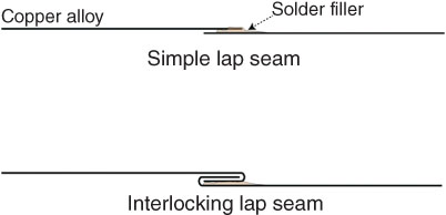
FIGURE 6.23 Two solder joints on thin sheet material.
For a soldered or brazed joint to be effective, the filler material must bond with the surfaces of the copper alloy. This is referred to as “diffusion.” The clean metal surface is heated to above the melting point of the filler material. As the filler material touches the hot base metal it liquifies and is pulled into the joint by means of capillary pressure, filling the space as it mechanically keys into the surfaces. The metal is allowed to cool and the filler solidifies, making a metallurgic bond between the filler and the surface of the base metal. The joint must be tight to facilitate the forces of capillary action.
When applying heat to the base metal to be joined, it is important to heat the entire joint. The heat first melts the flux, which wets the area to be joined. This activates the surface of the base metal. Next the filler metal is melted and drawn into the joint, effectively filling the gap between the base metal pieces.
Welding
Copper and copper alloys can be welded by all conventional means used on other metals. There are differences, however, that must be considered for effective welding to occur. Copper and most of the alloys have high electrical and thermal conductivity. For welding this means the heat of fusion is conducted away more rapidly and incomplete welding of the base material may occur, leading to higher porosity around the weld.
In copper alloys, in particular those that contain high levels of zinc, the zinc will vaporize during the heat of welding and fume from the molten metal. This can deplete the zinc in the weld area, leading to color differences when finishing processes are undertaken. The fumes are also hazardous and proper venting and protection should be practiced.
Copper alloys get their strength from cold working. The intense heat generated from welding will produce a weaker assembly. Thickness and shape may be needed in the design to overcome this decline in strength. The high thermal expansion coefficient of copper will also increase weld distortion concerns. These too, require proper design and assembly to overcome.
For all copper alloys it is important to begin with a clean, oxide‐free surface before attempting to weld. Copper oxides will hamper welding in a way similar to soldering.
Beginning with an oxide‐free surface is the first step in successfully welding materials to be joined.
As welding proceeds, the use of special fluxes or gas atmospheres around the weld must be utilized to prevent the oxide from returning during the welding process. This would lead to porosity in the weld.
Preheating the parts to be joined will reduce the issue of thermal conductivity and allow for lowering the heat input into the weld joint and in interpasses. This will help reduce cracking as the metal cools.
Welding Copper
Copper can be welded using arc welding techniques. Those techniques using gas shielding, such as an argon gas, provide the needed shielding to keep oxides from forming. When welding copper, consider using the gas metal arc welding (GMAW) or the gas tungsten arc welding (GTAW) process. Other methods can be used, but achieving good results is more difficult. Note that with copper, the finish will be consistent and oxidation—either naturally formed or artificially formed—will cover the metal well. The images at the left in Figure 6.24 show examples of welding C22000 seams and edges, while image on the right shows copper bar being welded for a handrail.
Thin copper can be welded. The difficulty comes with achieving a smooth weld without weld distortion. Figure 6.25 shows a very difficult weld being made on 1.2‐millimeter‐thick copper. The dimples help to add stiffness to the elbow, allowing a very fine weld to be laid down to join the copper. Copper rod was used as the consumable and the resulting joint was post‐polished.
Welding Brass Alloys
There are several issues to overcome when welding brass alloys. Esthetic challenges can develop when matching the color of the alloy at the weld. The constituents in the copper alloy, specifically zinc, will vaporize and there is a need for using fillers to help put some of the zinc back. The better solution is to attempt to design the weld in a less visible location. Statuary patinas applied to the weld area will also react differently and appear different. Patinas are not paints and will not cover. They may darken welds and make them less visible, but the point of statuary finishes and patinas is to react with the metal to create a particular color, and the metal at the weld is different.

FIGURE 6.24 Left: Welding of C22000 plates. Right: Welding of a handrail using the C11000 alloy.
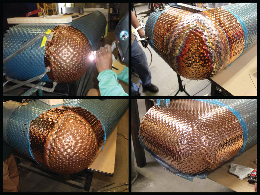
FIGURE 6.25 Welding of a copper elbow for the Prada store in Tokyo.
Brasses with a low zinc content (C21000, C22000, and C23000) can be welded. C26000 is more difficult to weld and its color will change. This alloy has 30% zinc. Brasses with a low zinc content are single‐phase alloys and tests should be performed when welding to determine if the color at the weld line is acceptable. GMAW and GTAW are best for welding these alloys.
Alloy C28000 is a two‐phase alloy containing as much as 40% zinc. This creates difficulties in welding and the arc welding processes for the single‐phase alloys works marginally on the C28000 alloy. The biggest challenge is the color. It will change at the weld as the zinc vaporizes and the metal cools.
The alloys containing lead, such as Architectural Bronze (alloy C38500), will not weld. They can be brazed, but welding the leaded alloys is not practical. The cast brass alloys are difficult to weld due to the inconsistent makeup of the casting. They are not as consistent as their wrought cousins. Many cast brass alloys include other elements, and some have small amounts of lead. These leaded castings will not weld.
Welding Silicon–Bronze Alloys
The silicon–bronze alloy C87300 is the cast alloy commonly used in art sculpture. This alloy has excellent welding characteristics. It has low thermal conductivity as compared to other copper alloys and the slag induced during welding provides protection from oxygen as the weld cools. The preferred methods of welding are gas shielded arc welding and gas tungsten arc welding, (GTAW). Alloy C87300 and the other silicon–bronze alloys can be welded with oxy‐fuel gas and shielded metal arc welding (SMAW).
Welding the cast alloy C87300 can achieve a close match between the surface and the joint, but it will not be exact due to the variations in the cast alloy. Grinding and finishing the weld back followed by patination can conceal the weld joint, but if weathering is allowed to occur on the surface, the weld can become visible as in the two cast bronze artworks in Figure 6.26.
The left‐hand image in the figure reveals a weld beginning to show as weathering has reached the patina. The right‐hand image shows a porous weld in a casting.
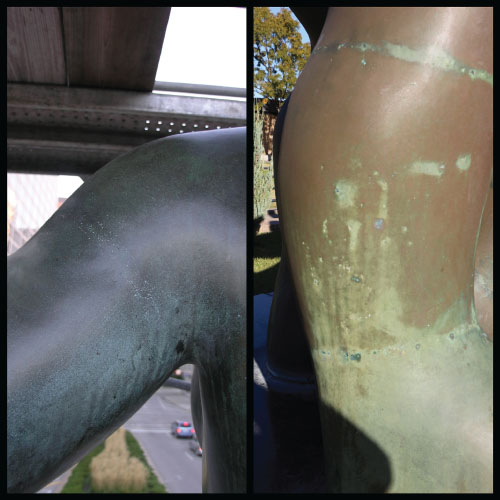
FIGURE 6.26 Visible welds on weathered cast bronze.
The parts being welded need to be clean and free of moisture and oils. When welding cast silicon bronze, be sure all sand and core material is cleaned from the surfaces. Preheating will drive the moisture away from the surface.
Welding Nickel–Silver, Phosphor–Bronze, and Aluminum–Bronze Alloys
Nickel–silver alloys can be welded. The zinc content creates issues similar to those of the brass alloys. The zinc vaporizes at lower temperatures than the nickel or copper. The biggest issue in welding nickel–silver alloys is the color match at the weld. It is not really possible to achieve a color match, and due to the esthetic quality of this alloy, an inferior color match can be a significant issue to overcome. Good design and reducing or concealing the welds or fusing the edges using GTAW techniques will work on thinner sections welded at edges. Nickel–silver alloys can be fusion stud welded effectively due to their lower conductivity.
Phosphor–bronze alloys can be welded using GMAW techniques coupled with preheating and sustaining the heat during the weld process. Other methods of welding (GTAW and SMAW) can also be used, but more selectively. The phosphor bronzes that are copper–tin alloys have a wide freezing range, meaning that they can crack along the weld as they cool from the welding operation.
Aluminum–bronze alloys used in art and architecture are usually not welded as they tend to crack. Alloy C61300 is preferred for welding situations, and even though it has slightly less than 7% tin, the addition of tin helps in the welding process. All of the arc welding processes can be used. A suitable shielding gas of argon or argon and helium should be used in most welding applications. Preheating is not needed for aluminum–bronze welding.
See Table 6.6 for a list of welding processes and their effectiveness when used on various copper alloys.
TABLE 6.6 Welding processes used on copper alloys.
| Welding process | Performance | Description |
| GTAW | Excellent | Argon, helium, or mix |
| PAW | Excellent | Argon, helium, or mix |
| GMAW | Excellent | Argon, helium, or mix |
| SMAW | Good | Noncritical welds |
| Oxy‐fuel | Good | Less warpage |
| Laser welding | Poor | Susceptible to cracking |
| Electron beam | Excellent | All alloys |
| Spot welding | Poor | Poor resistance at weld |
| Fusion stud welding | Good | Brass studs to copper |
GTAW: gas tungsten arc welding; PAW: plasma arc welding; GMAW: gas metal arc welding; SMAW: shielded metal arc welding.
CASTING
The Lost‐Wax Technique (Cire Perdue)
Casting with copper using the lost‐wax technique is nearly as old as the metal's discovery and use by humans. The first copper was hammered from native forms of large nuggets of the metal, but not long after man found the metal could be melted and reshaped into new forms. This surely was a remarkable discovery. Imagine when the first broken copper tool or dish was melted down and poured anew into a wood or clay mold and a new shape was born. No other material would have offered this utility. Among the discoveries of man, this has to stand as one of the most remarkable. Now tools could be fashioned and shaped for a particular use, and hardened and sharpened into useful tools. When no longer useful or when damaged they could be remelted and refashioned. No stone, wood, or clay material known up to this time in history afforded this incredible versatility.
After weapons and tools, ornamentation was next. Early man found that he could shape clays, heat them to harden them, and pour molten metal into the clay forms. This was most likely the beginning of casting a one‐sided detailed surface or ornament. At some point the discovery of how to form the clay over another material was made, and a similar process is still in existence today. This process is known variously as lost‐wax casting, cire perdue, and investment casting.
As discussed previously, the process involves carving a form or shape out of wax followed by fashioning clay on the wax to make an outer refractory shell around the wax and capturing the detail carved into the wax. The mold is heated in an oven and the wax melts out, leaving a refractory clay negative of the original wax. Metal is poured into the mold cavity, and as it hardens it takes on the original wax form.
This process works for small objects, but for larger objects the technique is somewhat different.
A clay model is created and all the detail is put into the clay model. Another mold is made from this clay model. The mold is usually refractory sand. When complete, its contours match the original clay model contours. Hot wax is coated onto the surface to a thickness that will eventually be the thickness of the final copper alloy casting.
This wax mold is then filled with more refractory material. This is called a core. Wax tubes are created and located by skilled foundry workers. The wax tubes will provide the passageway for the metal to flow and vents for the air to escape as the metal flows into the mold. Refractory sand is packed around the form with wax vents and ducts in place. The entire object is placed in an oven and the wax melts out. Usually metal pins are set as well to hold the core in place once the wax melts out.
Molten metal is poured into the ducting system by way of a feeder system of reservoirs, and the molten metal flows into the cavity left by the molten metal. Once cooled, the metal casting is removed from the mold and the core of refractory material is removed. The pins are then cut from the surface and the vents and ducts are removed.
At the foundry, the mold is prepared to receive the molten metal. The mold is generally made of sand, but there are also ceramic molds, lost‐wax investment molds, and several others. But sand molds are the most common in use for sculptures in copper alloy. Several examples of sand cast objects are shown in Figure 6.27.
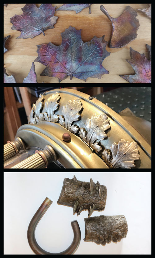
FIGURE 6.27 Various examples of sand‐cast shapes, from simple to intricate.
Difficulties in the casting process that manifest during and after the pour of the molten metals will translate to the finished product, sometimes causing the product to be rejected; the product must then be recast at the foundry. More often the cast is reworked to salvage what would otherwise be a good cast.
A few of the casting difficulties and their causes are listed in Table 6.7. These are nearly always addressed at the foundry before the sculpture or casting is delivered.
TABLE 6.7 Various surface maladies seen on castings.
| Problem | Cause |
| Cracks | The metal pulls itself apart while it is cooling in the mold. This is often caused by imbalanced feed rates to different volumes of the sculpture. It can also be caused by a casting temperature that is too high or too low. |
| Cold shut | The metal does not join together where two or more streams feed the casting. A weak area or void is created. This is due to inadequate gating or dross entering the sprue. Wet sand or insufficient venting can also cause this defect. |
| Wormy surface | These are depressions near the gate. They appear as stretch marks or worm tracks. These are caused by inadequate gating, a high pour temperature, or low permeability of the sand used. |
| Sand wash | This is a rough surface, either lumpy or pitted, that is due to weak sand. Weak sand is often caused by an improper pattern removal from the mold or insufficient ramming of the mold. |
| Scab | This is a rough, slightly raised area on a casting. It can be caused by ramming sand that is too hard or too fine. |
| Core blow | This is a smooth depression on the inside of a cored casting and is due to a gas pocket above the core. It is caused by insufficient curing of the core or inadequate venting of the core. |
| Burning into sand | This is a rough sandy surface on the finish casting and is often caused by sand that is too coarse or too dry. Also, if the temperature of the pour is too high, this can create a rough surface, as the sand dries out too rapidly. |
| Gas holes | These are holes under the surface or at the surface of the finish casting. They can result from contamination in the pour or from the sand making up the mold being too wet. |
| Tin or lead sweat | This is whitish spots or a thin layer of whitish metal streaks on the surface. It is caused by inadequate venting or by interruptions in the pour process. It can also be caused by too small a gate, which will restrict metal flow and allow the metal to cool. |
| Rough or pitted surface | A rough surface on the casting or deep pits on the surface. This is due to inadequate care in the mold process and using a sand that is too coarse or allowing dross to enter the pour. |
| Solid inclusions | These are pieces of nonmetal materials in the casting from improper mold cleaning or an improper sand mixture. |
| Weak structure | This manifests as very small voids between the large crystals in the interior of the casting. It is due to inadequate gating and inadequate feed of the molten metal into the mold. It also could occur when gases are trapped in the melt. |
| Burning into core | This is characterized by roughness in the inner surface of the casting. This can be caused by a high temperature of the molten metal or from inadequate curing of the core. |
Post‐casting processes include removal of the core. The core creates the hollow interior space during the casting process. After casting the core is removed from the interior, leaving the casting hollow. There are instances where the core is not fully removed: interior sculpture will not be affected but outdoor sculpture with the core still in the cast will eventually have significant problems. All castings have some level of porosity. If significant amounts of the core are present inside the casting they will start to deteriorate and leach out onto the surface. They will appear as whitish blooms growing out from a central pore. Chapter 8 discusses this event, and Figure 8.30 shows an image of this defect.
Spinning
Spinning is a fabrication process used on wrought sheet material. Heat can be added to soften the metal and for performing shaping of thicker copper alloys. Spinning involves application of force to a spinning disk or plate of material. The material is stretched and shaped into a spinning mold as the force is applied. The greater the elongation an alloy and temper will allow under tension, the more able it is to be shaped via spinning. It is a characteristic referred to as the plastic–strain ratio.
The part produced is always symmetrical around a vertical axis. Hemispheres, cones, tubes, and dish shapes can be created. The conical shape of musical instruments is an example of spun copper alloys. Light sconces, such as the one shown in Figure 6.28, are another example of products that can be produced with this method.
Copper (C11000) is the simplest to spin. Usually it can be formed without interstage heating to anneal the metal for further shaping. All of the single‐phase brasses can be spun, but those with higher zinc content may require annealing steps. Alloy C28000, Muntz Metal, and its sister alloy Naval Brass, C46400, cannot be spun. The phosphor bronzes, aluminum bronzes, and silicon bronzes are difficult to spin into anything but shallow disks because of their stiffness and cold working behavior.
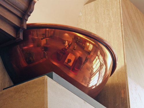
FIGURE 6.28 Spun and polished copper hemisphere light sconce.
Once the copper alloy parts are spun, they can receive finishing, polishing, statuary finishes, and patinas. Depending on the quality of the tooling and the skill of the operation, there may be radial lines imparted onto the surface. The lines are small and usually irregularly spaced. These lines are more pronounced on the side where the tool is brought to the surface.
Deep Drawing
As with spinning, the ability of a material to elongate while under tension determines its ability to be worked with deep drawing. This is the plastic–strain ratio referenced earlier: a measure of a material's ability to change in width and thickness as a tension load is applied. Many of the copper alloys have high, plastic–strain ratios. They can withstand stretching to a great extent before fracturing. Figure 6.29 shows a graph of a typical stress–strain relationship and the area where the metal will plastically deform until it fractures.
This ability is highly influenced by the mechanical behavior of the metal. Different copper alloys will work harden at different rates and this will affect the ability of the metal to undergo plastic deformation. Copper and many of the alloys of copper will elongate when subjected to a load. This allows for deep drawing of copper alloy parts. The alloys with the greatest percentage elongation have the ability to be deep drawn. Table 6.8 shows the elongation percentages for C11000 (commercially pure copper) under various tempers.
Temper induces stress into the copper by means of cold working operations. Extra spring has already moved up the curve to a point where very little additional forming can induce a fracture.
The other alloys have similar temper restrictions that, along with other mechanical properties, will determine the level of deep drawing they can undertake. Some of the alloys work harden rapidly and will have short and steep plastic deformation curves.

FIGURE 6.29 Plastic deformation zone before fracturing.
TABLE 6.8 Elongation of C11000 by temper designation.
| Temper | Elongation % |
| M20 Hot rolled temper | 50 |
| H00 1/8 hard temper | 40 |
| H01 1/4 hard temper | 35 |
| H02 1/2 hard temper | 14 |
| H04 Full hard temper | 12 |
| H10 Extra spring temper | 4 |
Stretch Forming
Stretch forming is a method used to form curved or contoured parts as opposed to a straight linear break form. The process involves gripping the metal sheet, fabricated form, or bar or tube along the edge and pressing it over a die while pressure is being applied. The metal is simultaneously pulled while being forced over a die.
Once the pressure is released, the copper alloy form takes the shape of the contoured die. There will be a slight necking of the material, and for polished surfaces some “orange peel” texture may be apparent as the grains of the metal realign under the force.
Similar to spinning and deep drawing, the copper alloys with the greatest elongation percentage, will stretch form with less difficulty. The annealed tempers are better suited for stretch forming and usually possess the greatest elongation for a given alloy of copper.
Custom Embossing and Custom Perforating
The ductility of copper alloys allows for deep embossing and perforating without creating a significant amount of residual stress. When metals sheets are shaped and punched to create perforations, often residual stresses build up around the initial indentation as the metal first elongates. In perforating and embossing, the metal is restricted around the zone where the work is to occur. This happens by means of a tool that clamps the metal surface or through pressure from metal‐to‐metal contact. The metal is restrained top and bottom. Where the metal is not restrained or supported, it elongates from the pressure into a cavity. In the event of embossing the pressure is limited. In the event of perforating, the pressure is increased to the point that a fracture develops as the slug of metal is sheared. In a real sense this is modern repoussé by means of computer‐controlled mechanisms. The top and bottom images in Figure 6.30 show custom perforating and the middle image shows custom embossing on copper sheet.
Custom embossed copper was used extensively by Herzog & de Meuron when the firm designed the de Young museum of art in San Francisco (Figure 6.31). For this project it was necessary for the fabricator to adjust the temper of the copper sheet to allow for the severe shaping that happens when numerous, discrete deformations occur. The metalwork hardens on a localized basis and this induced internal stress shapes the panel in unpredictable ways. To compensate, the fabricator adjusted the temper to allow for the added stress buildup.
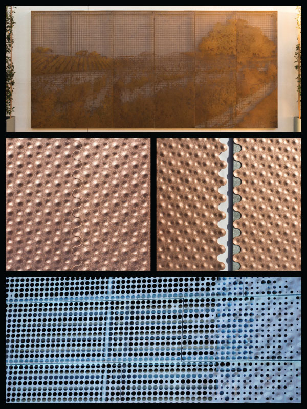
FIGURE 6.30 Custom perforating and embossing.
Other means use rolls made of hardened steel with matching engraved designs. The metal is fed between the rolls and the pattern is pressed into the metal. A pattern can also be imparted by means of a cavity and hard rubber or by means of a cavity and hydraulic pressure, as shown in Figure 6.32.

FIGURE 6.31 Custom embossed copper at the de Young museum of art
Source: designed by Herzog & de Meuron.
To produce economical surfaces, patterns are engraved into matching rolls, of which one has a positive pattern and the other has a negative copy. The rolls are aligned and the metal is fed through in coil form or sheet by sheet.
All copper alloys in wrought sheet form can be patterned in this way. There are limitations on thickness for each process as well as pattern limitations. In custom embossing, the limitations are thickness (which usually needs to be less than 4 mm) and geometry. The embossed deformation must be outside the clearance of the hold‐down mechanism used to constrain the sheet. Figure 6.33 shows the way in which the hold‐down operates, and the minimum clearance needed. If the clearance is encroached upon, the hold‐down will crush the previous embossed form.
This constraint doesn't exist for perforating, since there is no embossing to be crushed. However, there are constraints on the relationship between the size of hole and the thickness of the copper alloy sheet. The softness of many of the copper alloys is not as limiting as other, harder metals. Still, there are rules around the metal thickness and minimum hole diameter when using a piercing tool to produce the hole. When the hole is very small the tool used to pierce the metal drags some of the metal around the edge with it, and as it pulls out of the hole this can drag on the tool and distort the edge. The harder the alloy the better the pierce is. For soft copper alloys, the edge‐to‐edge distance of the hole should be 50% or greater than the metal thickness.
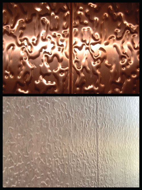
FIGURE 6.32 Roll embossed finish: (top) unaged surface; (bottom) a finish exposed for 12 years.
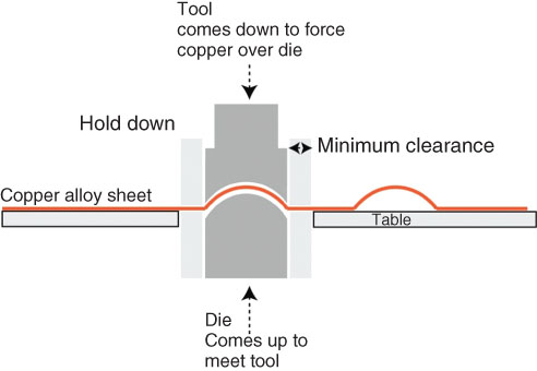
FIGURE 6.33 Diagram showing hold‐down clearance needed for custom embossing.
These forming operations relate back to processes of shaping copper alloys thousands of years ago. Copper is the perfect metal for forming and shaping. Its plastic behavior is exceptional and has been used by artists and designers to accomplish some of the most remarkable work ever created using metal.