ONBOARD MECHANICAL AND ELECTRICAL SYSTEMS are becoming increasingly complex as the years roll by. This chapter discusses some of the basics. Information on new and updated methods and equipment can be found in yachting and commercial craft publications and online sites. Advancements in LED lighting, hybride power systems, and “fly-by-wire” control systems are occurring at lightning pace—read all you can and use this chapter as a foundation for how you adapt the new systems to your project.
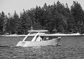
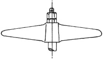
Zogo, a hybrid diesel-electric launch designed and built in Maine, is just one recent example of a unique approach to solving the propulsion puzzle for a powerboat. (Molly Mulhern)
Propeller shafts must be made from strong, noncorrosive material. At this writing two of the best metals, Monel Calloy 400 and the higher-strength monel Alloy K-500, have just about priced themselves out of the pleasure-boat market. These are high in nickel content, and this is probably the reason why little people, unlike governments, cannot afford them. A somewhat weaker metal, although “standard” for many years, is Tobin bronze, but this seems to have disappeared (but don’t overlook the possibility of finding a used Tobin shaft) and been replaced by various stainless steel shafting materials, notably Armco’s Aquamet 17, 18, and 22. If the shaft is going to be turning most of the time, as in commercial boat use, then Aquamet 17 is a strong, suitable metal, but in typical intermittent yacht service Aquamet 22 is a better choice. During the 1980s Aquamet 22HS was developed, and its strength is impressive. In the 2″- to 3″-diameter range, for example, yield strengths have increased enormously; Aquamet 22HS has a yield strength in tension of 105,000 pounds per square inch (psi) versus 75,000 psi for Aquamet 22, and a yield strength in torsion of 70,000 psi, compared to 50,000 psi. Horse-power of engines used in pleasure craft has been increasing, so the higher-rating Aquamet 22hs is beneficial in holding down the diameter and thus the weight of shafting. Shafts of this alloy may not exhibit as much corrosion resistance as those of Aquamet 22, however.
If your boat plans do not specify the shaft diameter, American boat and yacht council standard P-6 has charts for selecting the sizes of shafts for the materials mentioned above and also for bearing spacing.
Typical shafts have a keyway machined on one end for the propeller shaft coupling to the engine, while the outboard end has a taper with keyway to match the propeller hub bore and threads for the propeller locking nuts. The tapering must be carefully done so the propeller will fit properly and is best left to a shaft supplier who is set up for this work. For instance, standard taper for the propeller is 1/16 inch per inch, which is an angle of 3°34′47″ (total included angle). Dimensions for machining the shaft end and propeller hub have long been standardized, at least in the United States, and the relevant SAE data is usually tabulated and illustrated in the catalogs of the propeller makers. When setting up the length of your shaft, allow one shaft diameter’s clearance between the propeller hub and the strut.
Figure 20-1 shows a longitudinal section at the shaft centerline of a twin-screw motorboat. The same section applies to a common single-screw motorboat with a keel batten and cutaway skeg. It shows the usual modern arrangement of a rubber-necked shaft log with a stuffing box inboard to prevent water from leaking into the boat around the shaft, and a strut to support the shaft at the propeller. Intermediate struts are used when the shaft is sufficiently long to require additional support.
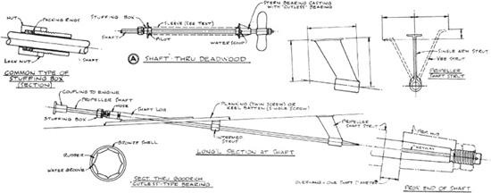
FIGURE 20-1. Various shaft details of shaft including propeller strut details, as well as stuffing box details.
The stuffing box and the shaft log are both of bronze and are connected by a short length of rubber hose secured by clamps. The hose helps to reduce vibration due to minor misalignment of the shaft. Shaft logs are made in the several angles that have proved the most useful for the majority of boats, but they may have to be shimmed with a wedge of wood in your boat to get the correct alignment. The base flange of the shaft log must be made watertight by bedding the flange with a generous amount of bedding compound or adhesive sealant. Wherever possible, the base should be through-fastened with silicon bronze bolts; otherwise wood screws of the same metal should be used.
The shaft hole through the wood should be treated with epoxy resin, because the hole is difficult to clean and paint later with the shaft in place and is therefore susceptible to worm damage. This precaution is very important indeed.
Some shaft logs are designed with a tube integral with the base. The tube is a lining for the shaft hole and is cut off flush with the outside of the hull. This type of shaft log is rather special and is not used as frequently as the kind that terminates at the base.
Another type of special shaft log is sometimes used in moderate- to large-size boats where the shaft is quite long in proportion to the diameter and it is desirable to have a bearing between the first intermediate shaft strut and the engine. In this case shaft logs are made that have a short length of bearing. The bearing is housed so the forward end is not exposed to a flow of water; water lubrication is provided by engine cooling water tapped into the log forward of the bearing. The water used is part of that usually piped into the exhaust line for cooling, but the diversion is not detrimental, because only a small amount is sent to the shaft log bearing. This type of shaft log is specially made up and not found in marine supply catalogs.
Some perfectionists object to a stuffing box that drips water, even only a normal amount, and for years I knew of only one shaft seal with zero drip, but such seals are now available. One of these is the lasdrop, made by the Lemania company and said to have American Bureau of shipping approval. (Addresses of this and other sources are listed in the Appendix.) The descriptive brochure lays out the entire device in color, much better than the photograph, Figure 20-2, and explains the function of the hose going into the top of the seal assembly. That hose is either to supply water as a lubricant to the seal faces in high-speed boats, which may have dry stern tubes when at planing speeds, or used as a vent line in low-speed displacement hulls to make the unit self-priming.
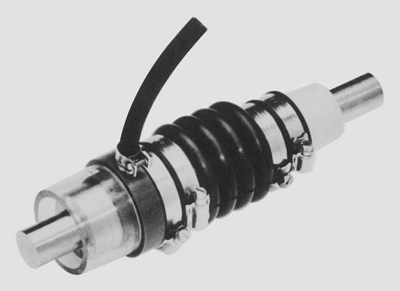
FIGURE 20-2. Lasdrop propeller shaft seal. (Lemania Company)
A part of the propulsion setup that is almost always a special item is the propeller shaft strut. As specified by the plans, it is either the single arm or the vee type, and due to the angle of the shaft and the shape of the hull it is nearly impossible to find a stock strut that will fit. There are, however, some adjustable struts on the market that might just do the job. Otherwise, enough dimensions on a sketch (as shown in A in Figure 20-1) or a mock-up must be sent to a strut manufacturer so he can make up one or a pair to fit the boat. Most struts are made of cast bronze.
Struts are fastened through the planking and the inside blocking with silicon bronze or manganese bronze bolts. The heads of the bolts should be oval and countersunk and should have a screwdriver slot to keep the bolt from turning while it is tightened. These bolts are best ordered from the strut manufacturer; specify the length needed.
You might as well have the strut maker install the bearing in the strut. It is hard to beat the Goodrich “Cutless”-type bearing, which is made of rubber bonded to an outer shell of bronze or, if the hull is aluminum alloy or steel, to an optional plastic-type shell. This type of bearing has grooves that channel in water for lubrication and for washing out silt and sand, thus minimizing shaft wear. The shell of the bearing is lightly pressed into the strut and secured with one or two set screws. The bearings are four times the shaft diameter in length when used as the aftermost bearing, and they are often reduced to half length in intermediate struts, so that one standard bearing can be cut to make two intermediate ones.
In Figure 20-1, A also shows a typical arrangement when the shaft of a single-engine boat goes through the deadwood. The stuffing box is inside the hull, the stern bearing outside. The latter has a Cutless-type bearing and a water scoop on each side of the casting for bearing lubrication. The stuffing box can be had “rubber necked,” with a piece of hose between the stuffing box and the casting. Both the stuffing box assembly and the stern bearing are stock marine hardware items and are readily available.
Water will fill the hole for the shaft and must be prevented from leaking into the hull through joints in the deadwood structure. This is done by fitting a tube between the stuffing box and stern bearing castings, either a lead sleeve as shown in A in Figure 20-1 (the lead is easily flanged by hammering) or a bronze tube special-ordered from a marine machine shop. The pilots of the castings can be tapped for the ends of a threaded pipe. The castings should be fastened to the wood with hanger bolts. Today fiberglass tubes are also used; they are available from Spartan Marine (see the Appendix).
The stuffing box packing is square, either waxed braided flax or teflonimpregnated asbestos braid, and is installed as individual rings, with the joints staggered so they are not all in line, thus preventing leakage.
When you have secured a propeller on the shaft with the thin nut against the hub, followed by the thick nut, don’t let anyone tell you it is wrong! Not Long ago the Society of Automotive engineers, which provides the marine propeller bore and shaft taper standards, revised their propeller shaft-end drawing to show the nuts properly arranged (see Figure 20-3).
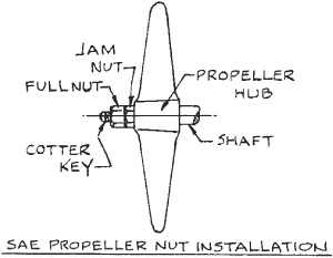
FIGURE 20-3. The proper arrangement of the nuts on the shaft end.
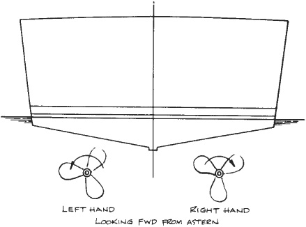
FIGURE 20-4. Shaft turning direction defines whether to install a left-hand or a right-hand propeller.
Screw propellers are made either right-hand or left-hand. Looking forward from astern, a shaft that turns clockwise requires a right-hand propeller and a shaft that turns counterclockwise takes a left-hand propeller. It is customary for the propellers in twin-screw boats to be of opposite rotation and to turn outboard as shown in Figure 20-4.
If there is misalignment between the engine and propeller shaft couplings, there will not only be unnecessary vibration when the engine is running but also possible damage to the rear bearing and seal of the reverse gear. The shaft should be installed first and the engine mated to it. If there are only two support bearings for the shaft—the stern bearing or strut bearing and a rubber-necked shaft log—block up the shaft inboard of the shaft log to prevent the shaft from sagging at the rubber neck. Lacking a feeler gauge, test for alignment between the coupling halves by inserting four strips of paper as shown in Figure 20-5. You can tell by gently pulling on the strips whether the pressure, and thus the gap, is the same for all pieces. Hardwood and thin brass shims are used under the engine mounts until the alignment is as perfect as possible. The final test is to tighten down the engine and still have good alignment of the couplings.

FIGURE 20-5. One method of testing shaft alignment.
Many engines are equipped with adjustable mounts that need but a wrench to lift or lower them a few thousandths of an inch, and some of the larger engines have jacking screws built into the mounts for the same purpose. Regardless, the fit of the coupling flanges is the important point.
If aligning of the engine is done with the boat out of water, it must be tested again when the vessel is launched because some hulls change shape when waterborne, throwing out the alignment that was done while hauled out.
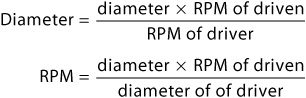
The boatbuilder is often faced with figuring out a v-belt pulley ratio when a bilge pump or extra generator is to be driven from a power takeoff pulley on an engine. The formulae below are handy for finding pulley diameter or speed in RPM.
Driven pulley:
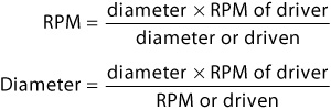
Driving pulley:
The engine is almost always located some distance away from the steering station of the boat, so remote controls must be installed for operating the throttle, the reverse gear, and an emergency shutdown in the case of some two-cycle diesel engines. This used to be done with complicated linkages of rods, pipes, and bell cranks and was a job of major proportions. One of the greater boons was the advent of the hydraulic reverse gear, requiring but fingertip effort on a small lever on the gear instead of the many footpounds of effort needed to operate the old manual clutch. This led to the push-pull cable controls now seen in most boats, a method that drastically reduced the time and cost of installation. The engine control system now consists of an attractive set of levers at the steering station and two push-pull cables running from the levers to the engine, one each for gear and throttle. The control maker usually has kits for each brand of engine for connecting the engine end of the cables to the gear and throttle. These save hours of making brackets for each job.
The length of cables between control levers and the engine can be almost unlimited, but they should be installed with a minimum number of bends, and the minimum bend radius for the size of cable being used must not be exceeded. Contrary to the opinions of some, it is a mistake to restrict the movement of push-pull cables. They should only be secured sufficiently to keep them from interfering with other equipment. A little time spent planning the cable runs will show which way has the least number of bends. The control manufacturers furnish excellent instructions for making the installation.
A variation of a control head with two levers per engine is the single lever control favored by many operators. Two cables per engine are still required, so the installation is planned the same as when there are two levers.
When two or more control stations are planned and would require long runs of cables with many bends, consideration should be given to hydraulic controls for the throttle and gears. Hynautic, Inc., has a system that may do the job for you.
The purpose of an engine exhaust system is to get rid of the gaseous products of combustion safely (without setting the boat on fire). The exhaust system also reduces the noise level and prevents water from backing up into and damaging the engine under all conditions of heel and trim. Such an arrangement is depicted in Figure 20-6, but this schematic does not show the effect of heel.
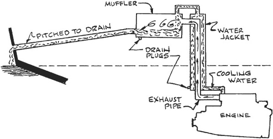
FIGURE 20-6. The basics of engine exhaust disposal.
Sailboats pose the worst problems because they often sail rail down. Figure 20-7 shows how to avoid a problem caused by heel. The water-jacketed tube for years was made of copper, a material relatively easy to work (NFPA 302 forbids the use of copper in contact with dry diesel exhaust gases), but copper is subject to pinhole leaks. Nowadays stainless steel is more commonly used. In sections where it is safe (see Figure 20-7) the exhaust can be hose that is approved for marine use.
In any event, metal water-jacketed sections are on the heavy side and expensive to make. Whenever possible the systems shown in the sketches thus far can be replaced by the so-called waterlift system. One type of waterlift system is illustrated in Figure 20-8, which shows typical installation with the exhaust outlet of the engine both below and above the waterline. Any restrictive dimensions should be heeded.
There are also vertical waterlifts that may better suit your hull. The makers should provide installation instructions.
Water, fuel, and electrical connections to an engine should always have slack so vibration cannot cause premature failure of the lines. Cooling water lines to the engine should be hose, double clamped at each end with stainless steel hose clamps whenever possible. On the other hand, fuel lines should be hose of approved type with threaded end and never clamped. The reader should heed the regulations described in the safety chapter.
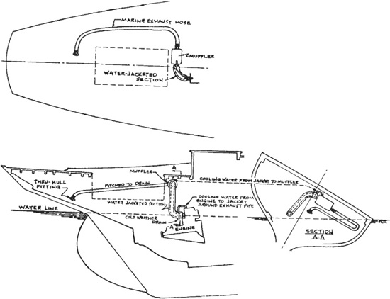
FIGURE 20-7. Details of water jacket installation on a sailboat.
A good number of boats have sunk because exhaust hoses have been inadequately clamped to the adjoining rigid pipes or tubes. Figure 20-9 shows the minimum clamp widths and hose overlap permitted by the American Boat and Yacht Council standard on this subject.
Here is a part of modern boatbuilding that can get a builder into a lot of trouble. If he is lucky, there will be only one voltage on board, such as 12 volts direct current. However, more often these days there will also be 115 volts of alternating current from a shoreline connection. This would be used to operate a charger to keep the batteries topped off, and also perhaps to operate the AC side of a dual-voltage refrigerator when the engines are not running and to operate air-conditioning while dockside. Progressing further, an AC independent generator on board can be used to provide conveniences such as an AC-powered cooking range, heating or air-conditioning, television, etc. And further along the line there can be two AC voltages in use aboard, and also two dc voltages, such as 12 and 24 or 12 and 32. The complications are endless; in some of the larger yachts there seems to be no end at all. But this has been recognized, and there are ABYC standards that attempt to keep things manageable.
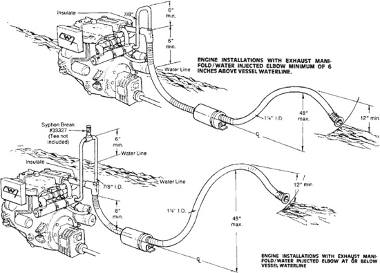
FIGURE 20-8. Waterlift-type muffler installations. (J. H. Westerbeke Corporation)
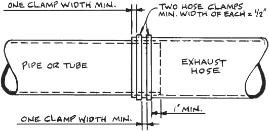
FIGURE 20-9. Double-clamping hose connections is critical for safety.
In terms of material, the standards are a guide to the all-important matter of overload protection to avoid fire and to the type of insulated conductors necessary to cope with the various environments aboard a boat. The conductor size is governed by the length of the wire and the ampere load to be carried, and the wires of the conductors should be stranded rather than solid to minimize failure from vibration. Connections must be by approved crimped terminals and should be soldered as well. Advice from an old friend: Solder electrical wire crimped connections with 60-40 rosin-core solder, not acid-core solder.
If you have access to ABYC standards, you’d best read and heed them well, remembering that the recommendations contained therein are a result of concern by the boatbuilding industry to help boatbuilders and owners avoid trouble. When a boat is large enough to have electrics, be sure to also heed the ABYC advice on bonding the equipment on board. A list of ABYC-recommended practices appears in “safety,” chapter 22.
The U.S. Coast Guard also has something to say about electrical installations, due to tragic experiences in the past, particularly in boats with gasoline engines. The Coast Guard’s guideline for safe electrical system installation is listed in the safety chapter.
Life is being made easier for the boatbuilder by the appearance on the market of switchboards meeting recognized standards. For years, the only hardware store–type switchboard available to boatmen was a small 12-volt DC panel having six to a dozen toggle switches and automotive-type fuses for circuit protection. Now, there are DC panels and combination DC and AC panels of various sizes, all having approved circuit breakers and meters to show loads and the condition of batteries. There is a sufficient selection of panels and load capacities to take care of the circuits used in many boats, and this often eliminates the necessity of having to utilize custom-designed, custom-built switchboards. Newmar, Blue Sea, and Paneltronics all have products in this area (see the Appendix). The panel in Figure 20-10 is for boats with only direct current. Available on a stock basis are panels designed as alarms, such as the engine, bilge water, and engineroom alarm panel in Figure 20-11. Also available is one that detects extremely dangerous cooking-gas fumes that escape due to a leak in the piping.
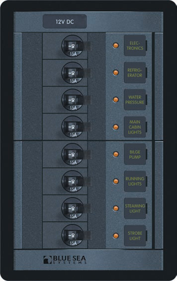
FIGURE 20-10. Typical neat, compact DC electrical panel for small craft. (Blue Sea)
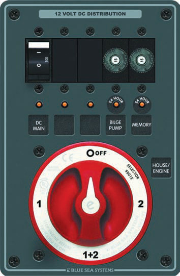
FIGURE 20-11. A specialized DC distribution panel that includes a battery switch. (Blue Sea)
Another maker of AC/DC circuit breakers is Paneltronics, which will provide a design manual upon request.
My boat-designer friend Fred Bates has over the years sold several hundred sets of plans for his 23-foot powerboat Pogo, a craft with just basic living accommodations. The schematic wiring diagram, which I have simplified somewhat by omitting wire sizes, is shown in Figure 20-12 and is typical of the direct-current systems in many small craft.
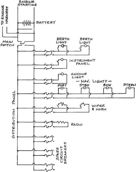
FIGURE 20-12. Schematic wiring diagram for 23-foot cruiser.
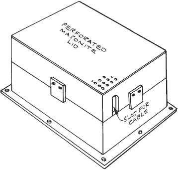
FIGURE 20-13. A suggested battery box design.
The electrolyte in a lead-acid storage battery is very destructive to wood and certain metals, so it is important to prevent spillage. The worst thing that can happen is for an unsecured lead-acid battery to overturn; therefore the battery, whether it consists of a single or multiple units, must be secured. New batteries, including gel-cell and AGM, are closed and do not poise the same potential for damaging leakage; however, all batteries are extremely heavy, so securing them well to the vessel is mandatory. For small craft, covered molded plastic cases with straps and hold-down fittings are available. In larger boats there might be a bank of two engine-starting batteries and a bank of two to eight ship’s-service batteries, for which custom boxes must be built.
One of the simplest containers is made of plywood, with its interior made acid-resistant by carefully and completely lining the box with fiber-glass. The inside dimensions of the box should be about ¾″ larger all around than the battery to provide space for spilled water, which can be removed by suction with an oven baster. A couple of expendable wooden blocks can be used to keep the battery from shifting despite the clearance. The top should be of a material such as Masonite, ventilated so that explosive hydrogen generated when the battery is being charged will not be trapped. A top also guards against the possibly dangerous sparking that would take place should a tool be accidentally dropped across the battery terminals.
Figure 20-13 is a suggested battery box for the do-it-yourselfer.